

DENSO HVAC System for Recreational Vehicles Service Manual
What's Included?
Fast Download Speeds
Online & Offline Access
Access PDF Contents & Bookmarks
Full Search Facility
Print one or all pages of your manual
Heating, Ventilation, and
Air Conditioning System
Service Manual for
Recreational Vehicles
This manual applies to vehicles
using HFC-134a refrigerant ONLY.

i
FOREWORD
This manual was developed to assist certified technicians in servicing the air conditioning system on
class A motorhomes built on Ford, GM, Spartan, or Freightliner chassis, equipped with a DENSO air
conditioning system.
Since the dash A/C system utilizes chassis components (compressor, condenser, receiver/drier and
discharge hose), it is advised that the appropriate chassis repair manual for Ford, GM, or Freightliner be
consulted when required or necessary.

ii

iii
TABLE OF CONTENTS
GENERAL INFORMATION .................................................................................................. 1
1. The Purpose of Air Conditioning ................................................................................ 1
2. Technical Terms .......................................................................................................... 1
3. Change of State ......................................................................................................... 5
4. The Relationship Between Pressure and Temperature .............................................. 6
5. Basic Theory of Cooling ............................................................................................. 7
6. Refrigerant .................................................................................................................. 7
7. Principles of Air Conditioning ................................................................................... 10
8. Automotive Refrigeration System ............................................................................ 11
SAFETY PRECAUTIONS ................................................................................................... 14
1. Safety Precautions ................................................................................................... 14
2. Ultraviolet Rays and Ozone Layer ............................................................................ 15
TOOLS AND EQUIPMENT ................................................................................................ 16
1. Service Tool Kit ......................................................................................................... 16
2. Handling of Service Tools ......................................................................................... 16
3. Robinair Enviro Charge 34700 Series ...................................................................... 18
TORQUE AND BOLT SPECIFICATIONS ........................................................................... 19
1. Standard Torque: Coupling Nut Type Fittings ......................................................... 19
2. Torque Specification for Bolts/Nuts/Screws ............................................................ 19
COMPONENT LOCATIONS AND POSITIONS ................................................................. 20
1. Interior Component Locations (All Models) .............................................................. 20
2. Raised Floor Measurements and Cutouts ................................................................ 23
TROUBLESHOOTING ........................................................................................................ 24
1. Troubleshooting Table .............................................................................................. 24
2. Troubleshooting by Manifold Gauge ........................................................................ 25
3. Visual and Audible Troubleshooting Questions ........................................................ 33
4. Troubleshooting Chart .............................................................................................. 34
5. Insufficient Cooling ................................................................................................... 35
6. Abnormal Noise ........................................................................................................ 38
COMPONENT TESTING .................................................................................................... 39
1. Blower/Cooling Unit ................................................................................................. 39
2. Compressor Fitting ................................................................................................... 42
3. Refrigerant Hoses/Tubes .......................................................................................... 42
4. Heater Hoses: On Vehicle Inspection ....................................................................... 42
5. Heater ....................................................................................................................... 43
6. Thermostat ............................................................................................................... 45
7. A/C Control System: On Vehicle Inspection ............................................................. 46
8. Control Panel Removal ............................................................................................. 46
9. Pressure Switch ....................................................................................................... 47
10. Blower ...................................................................................................................... 48
11. Relays ...................................................................................................................... 49
12. Air Intake Servo ....................................................................................................... 50
13. Vent Mode Servo ..................................................................................................... 51

iv
TABLE OF CONTENTS
REFRIGERANT LINE REPLACEMENT ............................................................................. 52
1. On Vehicle Inspection ............................................................................................... 52
2. Refrigerant Lines Replacement ................................................................................ 52
3. Torque Specifications ............................................................................................... 52
4. CHASSIS .................................................................................................................. 53
REFRIGERANT CHARGING .............................................................................................. 63
1. About Certification ................................................................................................... 63
2. Section 609 of the Clean Air Act Amendments of 1990 .......................................... 64
3. Evacuating and Charging Refrigerant ...................................................................... 65
4. Refrigerant Volume ................................................................................................... 67
5. Performance Test ..................................................................................................... 68
WIRING DIAGRAMS .......................................................................................................... 70
1
GENERAL INFORMATION
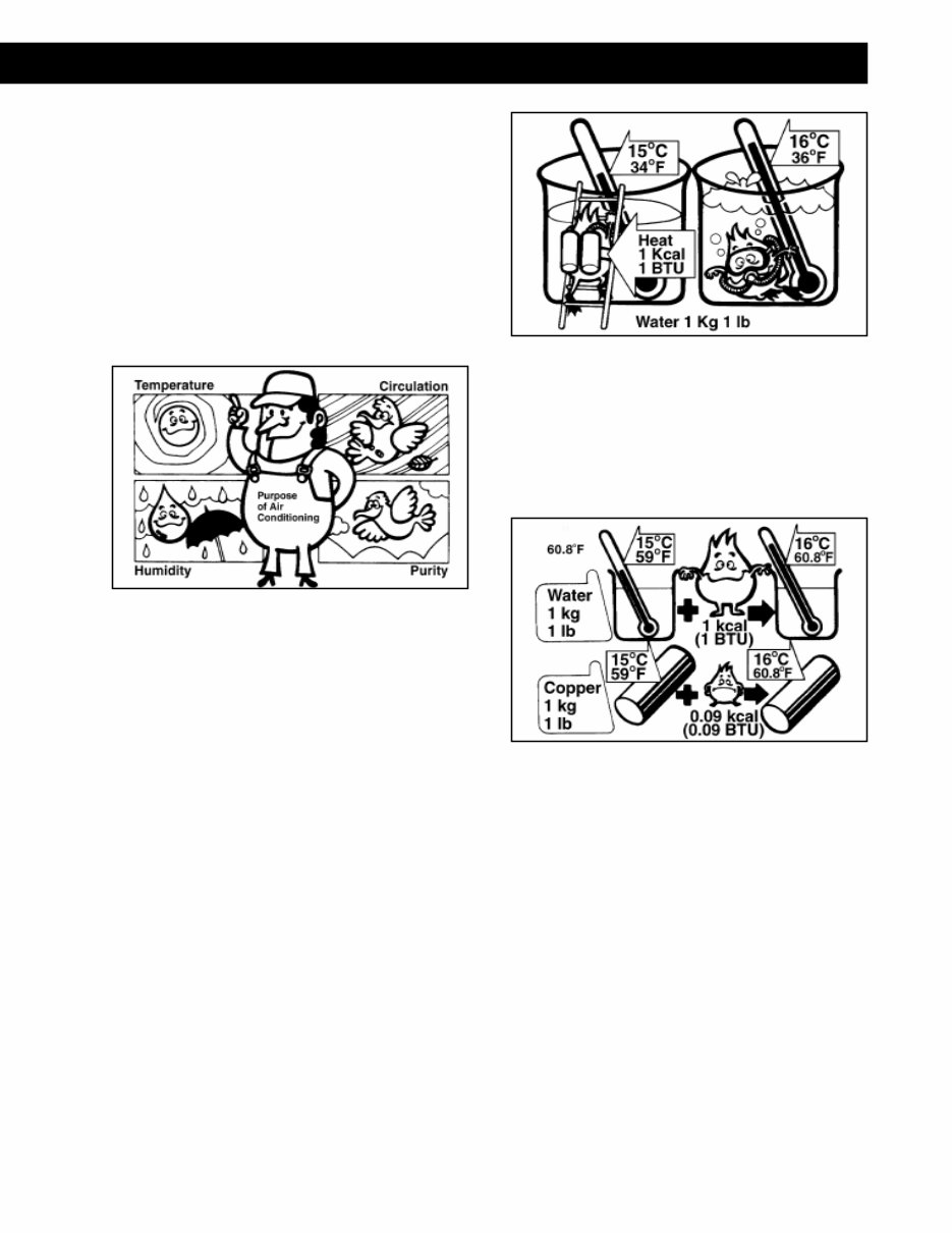
1. The Purpose of Air Conditioning
The purpose of an automotive air conditioner is to
maintain a cool, comfortable environment for
passengers.
Here are the four ways this is achieved:
• Temperature Control
• Air Circulation Control
• Humidity Control
• Air Purification
2. Technical Terms
A. Heat
1) Heat Quantity
Heat is a form of energy. There are two
units to measure heat quantity, Kcal or
BTU (British Thermal Unit).
• One Kcal heat quantity changes
the temperature of one Kg of liquid
water by one degree centigrade.
• One BTU of heat changes the
temperature of one pound of liquid
water by one degree Fahrenheit.
1 Kcal = 0.252 BTU
1 BTU = 3.968 Kcal
2) Specific Heat
Specific heat is the quantity of heat
required to CHANGE THE TEMPERA-
TURE of an object by one degree.
The unit of specific heat is Kcal/kg°C
or BTU/lb°F.
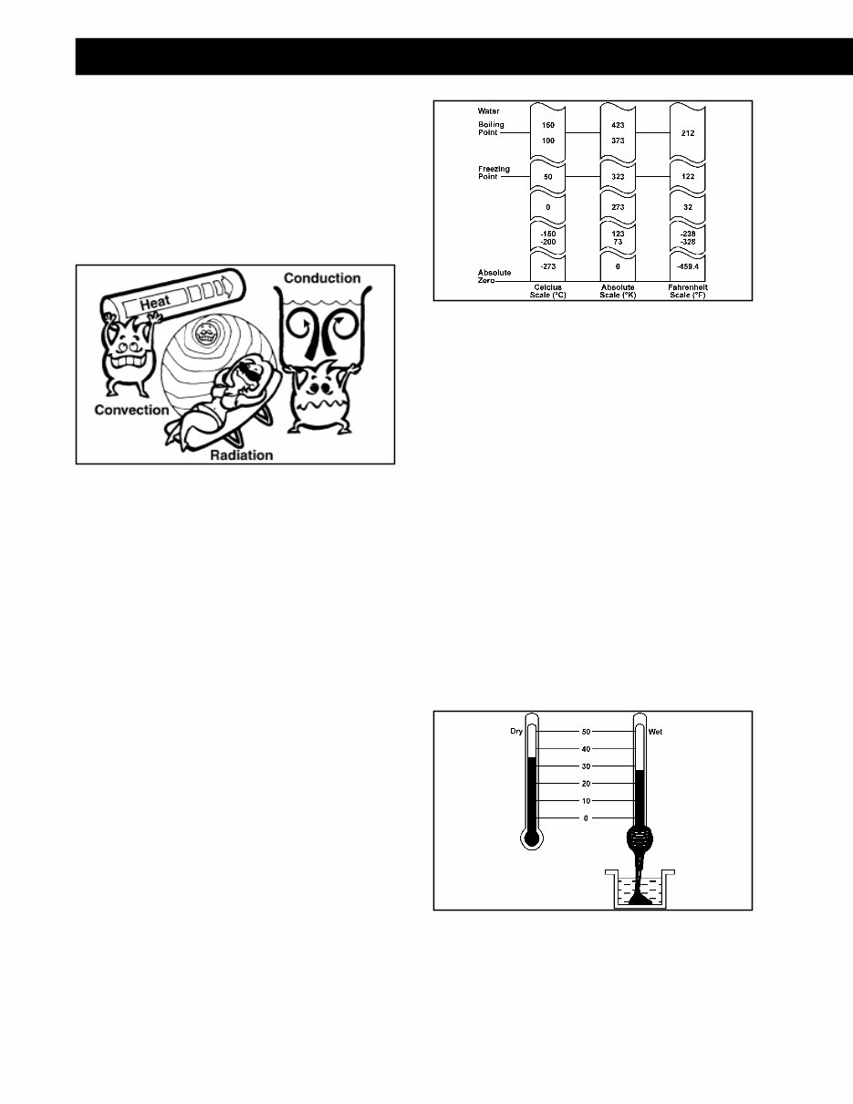
3) Heat Transfer
As heat travels over a distance, it
tends to lose energy. Heat can be
transmitted through CONDUCTION,
CONVECTION or RADIATION. It can
also be transmitted by a combination
of any or all of these methods.
a) Conduction is the transfer of heat by
direct contact. When you heat one
side of a steel bar, the other side
becomes warmer by conduction.
b) Radiation is the transfer of heat by
rays. Heat from the sun is trans-
ferred to the earth in rays. But the
sun isn’t the only object that
radiates heat. Every object that
contains heat can radiate it.
Fig. 1: The Four Factors of Air Conditioning
Fig. 2: Heat Quantity
Fig. 3: Specific Heat
2
GENERAL INFORMATION
c) Convection is the transfer of heat
by the movement of heated liquid
or gas. When heat is applied to the
bottom of a container of liquid or
gas, the warmed particles at the
bottom expand and rise. The
colder particles at the top, which
are denser than the heated par-
ticles, sink to the bottom.
B. Temperature
1) Temperature Scales
Temperature is the degree to which an
object is hot or cold. The unit generally
used to express this is degrees
Centigrade (°C) or degrees Fahrenheit
(°F). In the Centigrade scale, the
freezing point (solid point) of pure
water is taken as 0°C, and the dis-
tance between the freezing point and
the boiling point are divided into 100
parts and each part is designated as
1°C.
In the Fahrenheit scale, the freezing
point of pure water is taken as 32°F,
and the distance between the freezing
point and the boiling point are divided
into 180 parts with each part desig-
nated as 1°F.
[°C] = 5/9([°F] - 32)
[°F] = 9/5([°C] + 32)
2) Wet Bulb and Dry Bulb Thermometers
The bulb (heat sensitizing part) of a
glass tube thermometer is wrapped
with a gauze or other rough mesh
cloth. One end of the cloth is im-
mersed in a water container to allow
the water to be drawn up by a capil-
lary action and to moisten the heat
sensitizing part. The water in the cloth
surface near the heat sensitizing part
evaporates and robs the latent heat of
evaporation from the surrounding air,
causing the air temperature around the
heat sensitizing parts to drop. The
temperature registered by the ther-
mometer at this time is called the wet
bulb temperature.
This is used to find out the humidity
in combination with the dry bulb
temperature.
Fig. 4: Three Ways Heat is Transferred
Fig. 5: Temperature Scales
Fig. 6: Thermometer
3
GENERAL INFORMATION
3) Dew Point Temperature
When the air surrounding us is cooled,
the air temperature drops, and when
the humidity becomes 100%, that is,
when the dry bulb and wet bulb
temperatures become the same, the
water vapor contained in the air will be
in a saturated state.
On further cooling, the water vapor
reaches a condition where it cannot
remain in a vapor state so that a part
condenses and becomes dew. The
temperature at which the humidity
becomes 100% and dew is formed is
called the dew point temperature.
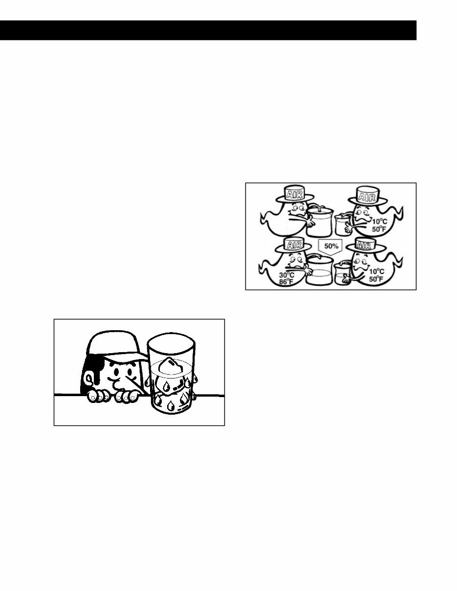
C. Humidity
1) Humidity
When you pour water and ice into a
glass, you notice that drops of water
are generated on the glass. Do you
sometimes wonder where these drops
of water come from?
Drops of water come from the sur-
rounding air, so humidity is water
vapor contained in the air.
2) Relative Humidity
There are two ways to measure
humidity: relative humidity and abso-
lute humidity.
The most common way to measure
humidity is using the relative method.
Relative humidity is the amount of
water the air contains, compared with
the amount the air could hold at a
given temperature.
In other words, if the relative humidity
is 50 percent, the air could hold as
much water again as it does at that
temperature.
Water capacity means the amount of
water vapor which the air could hold
at a given temperature. The water
capacity changes according to the
temperature of the air. The water
capacity of cooled air is lower. There-
fore, the amount of vapor in the air at
50°C, 50 percent, is different from that
in the air at 10°C, 50 percent.
3) Absolute Humidity
Absolute humidity is the amount of
water the air contains, compared with
the dry air.
D. Pressure
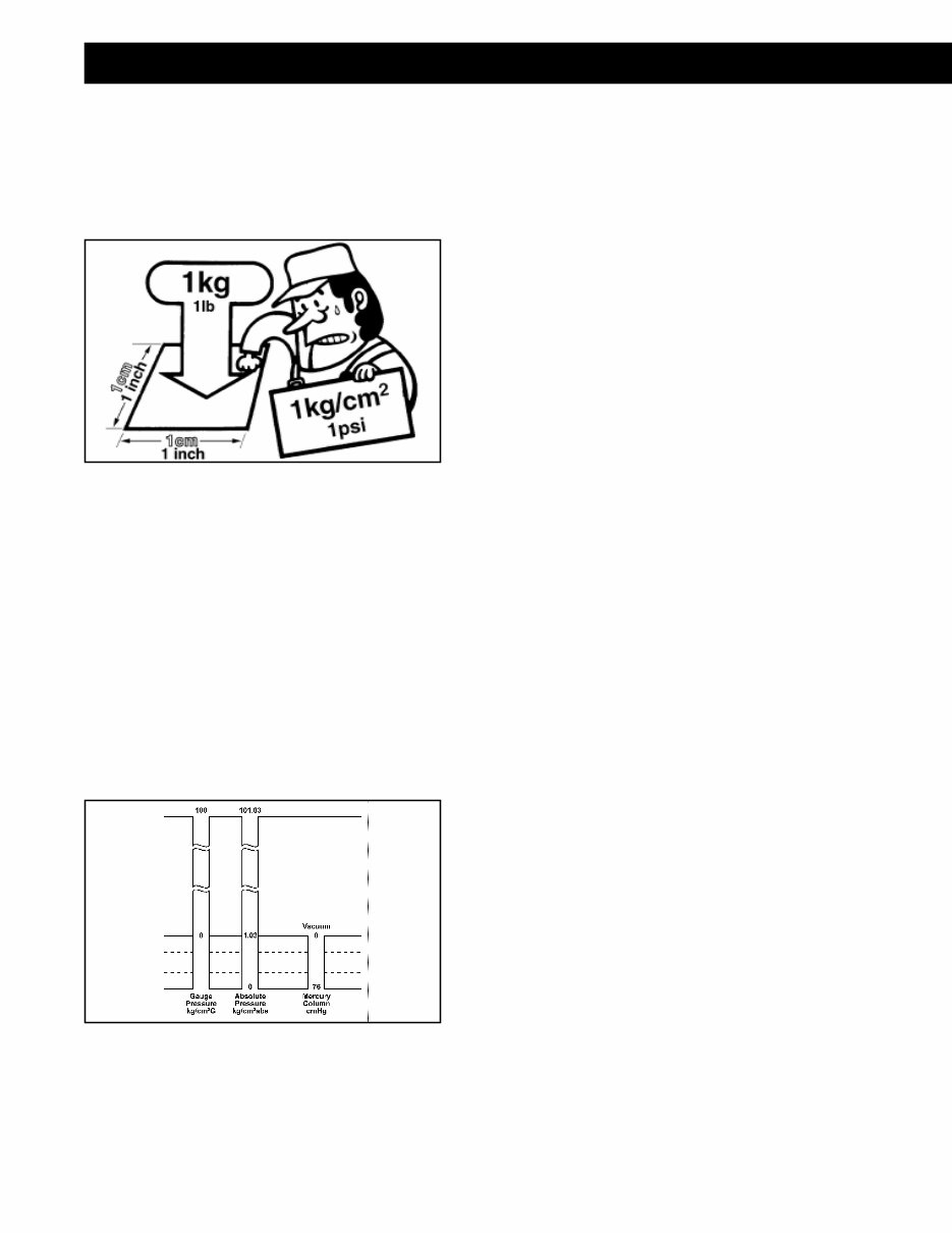
1) What Is Pressure?
Pressure is defined as the vertical
force exerted on a unit area by a solid,
liquid, or gas. The unit generally used
to indicate the pressure is “kg/cm”.
When indicating blower performance,
mmAq (water column) is generally
used, and when indicating pressure
below atmospheric (vacuum), cmHg
(mercury column) is commonly used.
When expressing boiler pressure, the
atmospheric pressure is taken as the
basis, and the pressure is expressed in
number of atmospheres (atmos). The
concept held toward pressure is entirely
in accordance with Pascal’s law.
Fig. 7: Humidity
Fig. 8: Relative Humidity
4
GENERAL INFORMATION
Pascal’s Law: “Pressure exerted on a
liquid confined in a container is
transmitted undiminished in all direc-
tions. Regardless of container shape,
if the interior area is equal, the pres-
sure subject there will be equal.”
2) Atmospheric Pressure
This is the pressure that is subjected
on all objects and matter on earth.
This pressure is the weight of the air
surrounding everyone and is equal to
1 atmosphere.
At this pressure the mercury column
will be 760 mmHg (76 cmHg).
1 atm=1.03 kg/cm
2
=760 mmHg=14.7 psi
Pressure gauges commonly indicate
atmospheric pressure in units of kg/
cm
2
or psi.
3) Absolute Pressure
Absolute pressure is that in which a
perfect vacuum is taken as 0 kg/cm
2
.
Thus, the atmospheric pressure, when
expressed in terms of absolute pres-
sure, will be 1.03 kg/cm
2
.
To differentiate, pressure measured
with a gauge is called gauge pressure.
For identification, absolute pressure is
indicated by [kg/cm
2
abs.] and gauge
pressure by [kg/cm
2
G]. Absolute
pressure to gauge pressure relation-
ship is as follows:
Absolute press. [kg/cm
2
abs.] + Gauge
press. [kg/cm
2
G] + 1.03 kg/cm
2
4) Vacuum
Vacuum is the pressure below atmo-
spheric pressure and is expressed in
terms of a mercury column (cmHg,
mmHg).
When the vacuum is measured with a
mercury column, the difference
between this measurement and that
for atmospheric pressure becomes the
amount of vacuum.
Fig. 9: Pressure
Fig. 10: Pressure Scales
5
GENERAL INFORMATION
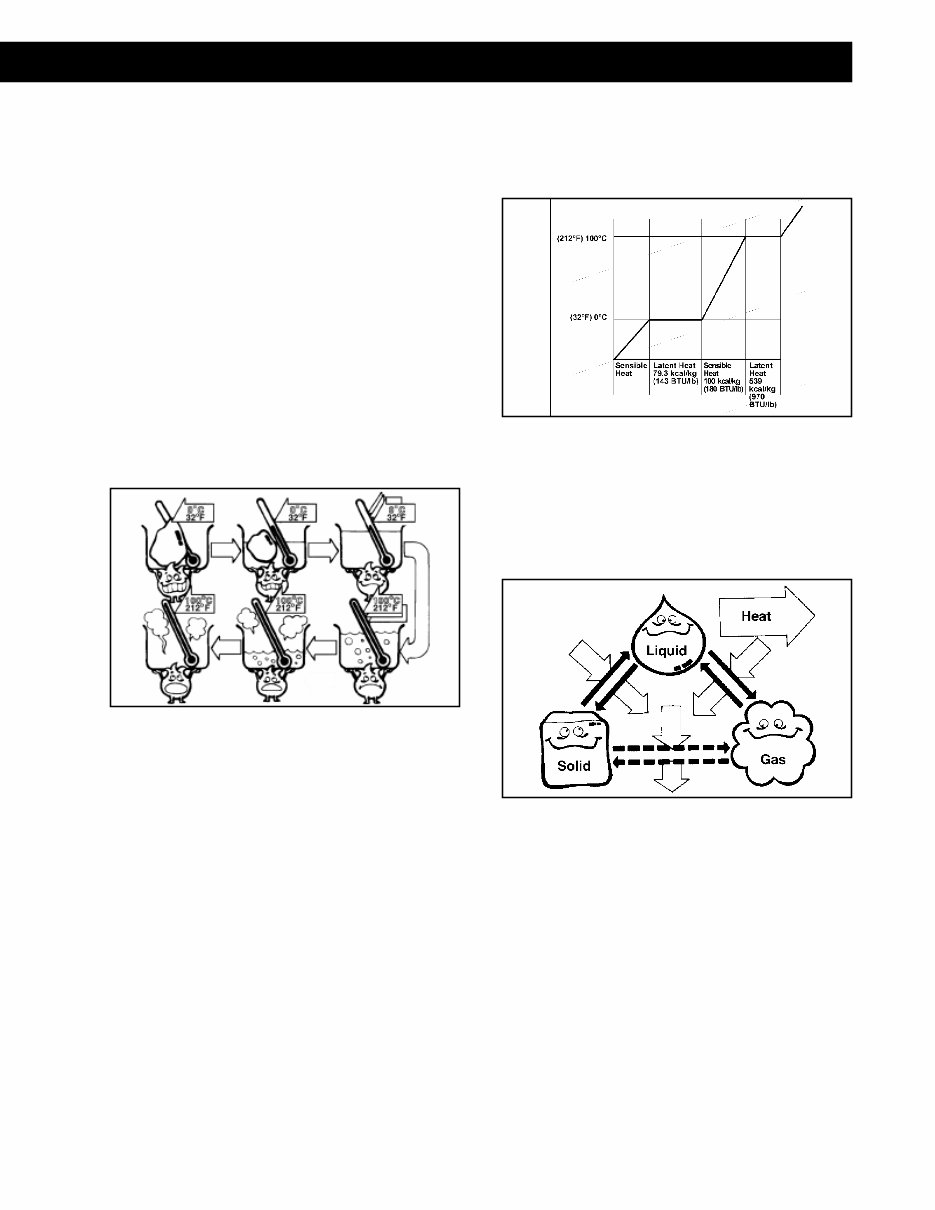
3. Change of State
A. State Change of Water
Now, we will consider how ice changes its
state when we add heat to it, because
water is the most common example to
understand heat and states of object.
If we add heat to ice until the temperature
of ice reaches 0°C (32°F), ice melts into
water, and while the ice is melting, the
temperature of ice and water remains at
0°C. After the ice has melted, the tem-
perature of water begins to rise.
When the temperature of water reaches
100°C (212°F), water begins to become
steam. Until all the water becomes steam,
the temperature of water remains 100°C
(212°F).
B. Sensible Heat and Latent Heat
The chart below shows the relation
between heat and temperature. There are
two kinds of heat called sensible heat and
latent heat.
Sensible Heat can change the temperature
of water but cannot change the state of
water. Therefore, the sensible heat raises
or lowers the temperature of water. In the
case of water, 1 kg of water at 0°C must
absorb 100 Kcal of sensible heat to
change to 1 kg of water at 100°C.
Latent Heat can change the state of water,
but cannot change the temperature of
water. Ice melts into water by adding
latent heat and water evaporates into
steam by adding latent heat. In the case of
water, 1 kg of ice at 0°C must absorb 80
Kcal of latent heat to change to 1 kg of
water at 0°, and 1 kg of water at 100°C
must absorb 539 Kcal of latent heat to
change to 1 kg of steam.
C. The Three States of Matter
As you know, matter exists in three states:
solid, liquid and gas. In the case of water,
the solid state is ice, the liquid state is
water, and the gas state is steam.
1) Fusion
When a solid melts into a liquid, heat
is absorbed from its surroundings.
2) Solidification
In the opposite situation, when liquid
changes into a solid, heat is released
to its surroundings.
3) Evaporation
When liquid evaporates into gas, heat
is absorbed from its surroundings.
Fig. 11: State Change Of Water
Fig. 12: Sensible Heat and Latent Heat
Fig. 13: Three states of Matter
You're Reading a Preview
What's Included?
Fast Download Speeds
Online & Offline Access
Access PDF Contents & Bookmarks
Full Search Facility
Print one or all pages of your manual
$32.99
Viewed 82 Times Today


Secure transaction
What's Included?
Fast Download Speeds
Online & Offline Access
Access PDF Contents & Bookmarks
Full Search Facility
Print one or all pages of your manual
$32.99
Denso Heating, Ventilation and Air Conditioning System Service Manual is designed for recreational vehicles utilizing HFC-134a refrigerant. This comprehensive manual, published in 2005 with a total of 83 pages, is available in English.
- Instant access: Yes
- Has bookmark for easy navigation: Yes
- Can be printed: Yes
- for Windows: Yes
- for Mac: Yes
The manual covers a wide range of topics including:
- General Information
- Safety Precautions
- Tools and Equipment
- Torque and Bolt Specifications
- Component Locations and Positions
- Troubleshooting
- Component Testing
- Refrigerant Line Replacement
- Refrigerant Charging
- Wiring Diagrams
It provides valuable insights into the purpose of air conditioning, technical terms, refrigerant principles, safety precautions, handling of service tools, torque specifications, troubleshooting techniques, component testing, refrigerant line replacement, charging procedures, and wiring diagrams. This manual is an indispensable resource for both professional mechanics and DIY enthusiasts.


