YANMAR 4TNE84 4TNE88 3TNE84T 4TNE84T Engine Full Service & Repair Manual
What's Included?
Lifetime Access
Fast Download Speeds
Online & Offline Access
Access PDF Contents & Bookmarks
Full Search Facility
Print one or all pages of your manual
SERVISE MANU INDUSTRIAL DIES MODEL TNE s
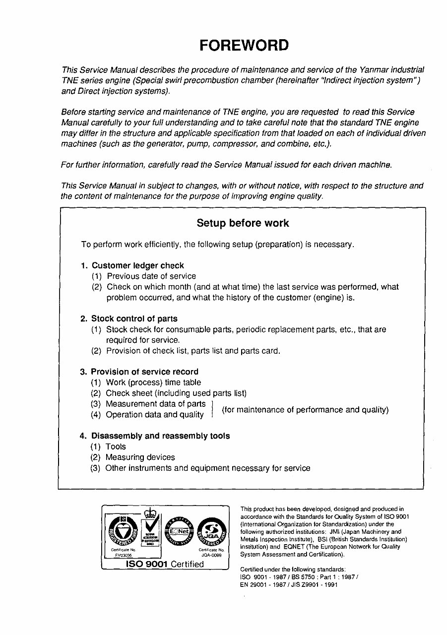
FOREWORD This Service Manual describes the procedure of maintenance and service of the Yanmar industrial TNE series engine (Special swirl precombustion chamber (hereinafter "Indirect injection system") and Direct injection systems}. Before starting service and maintenance of TNE engine, you are requested to read this Service Manual carefully to your full understanding and to take careful note that the standard TNE engine may differ in the structure and applicable specification from that loaded on each of individual driven machines (such as the generator, pump, compressor, and combine, etc.). For further information, carefully read the Service Manual issued for each driven machine. This Service Manual in subject to changes, with or without notice, with respect to the structure and the content of maintenance for the purpose of improving engine quality. Setup before work To perform work efficiently, the following setup (preparation) is necessary. 1. Customer ledger check (1) Previous date of service (2) Check on which month (and at what time) the last service was performed, what problem occurred, and what the history of the customer (engine) is. 2. Stock control of parts (1) Stock check for consumable parts, periodic replacement parts, etc., that are required for service. (2) Provision of check list, parts list and parts card. 3. Provision of service record (1) Work (process) time table (2) Check sheet (including used parts list) ~)~.uffimentd~~p~1 . . (4) Operation data and quality (for maintenance of performance and quality) 4. Disassembly and reassembly tools (1) Tools (2) Measuring devices (3) Other instruments and equipment necessary for service FM23056 JQA-0099 ISO 9001 Certified This product has been developed, designed and produced in accordance with the Standards for Quality System of ISO 9001 (International Organization for Standardization) under the following authorized institutions: JMI (Japan Machinery and Metals Inspection Institute), SSI (British Standards Institution) Institution) and EQNET (The European Network tor Quality System Assessment and Certification). Certified under the following standards: ISO 9001 - 19871 BS 5750: Part 1 : 19871 EN 29001 - 19871 JIS Z9901 -1991
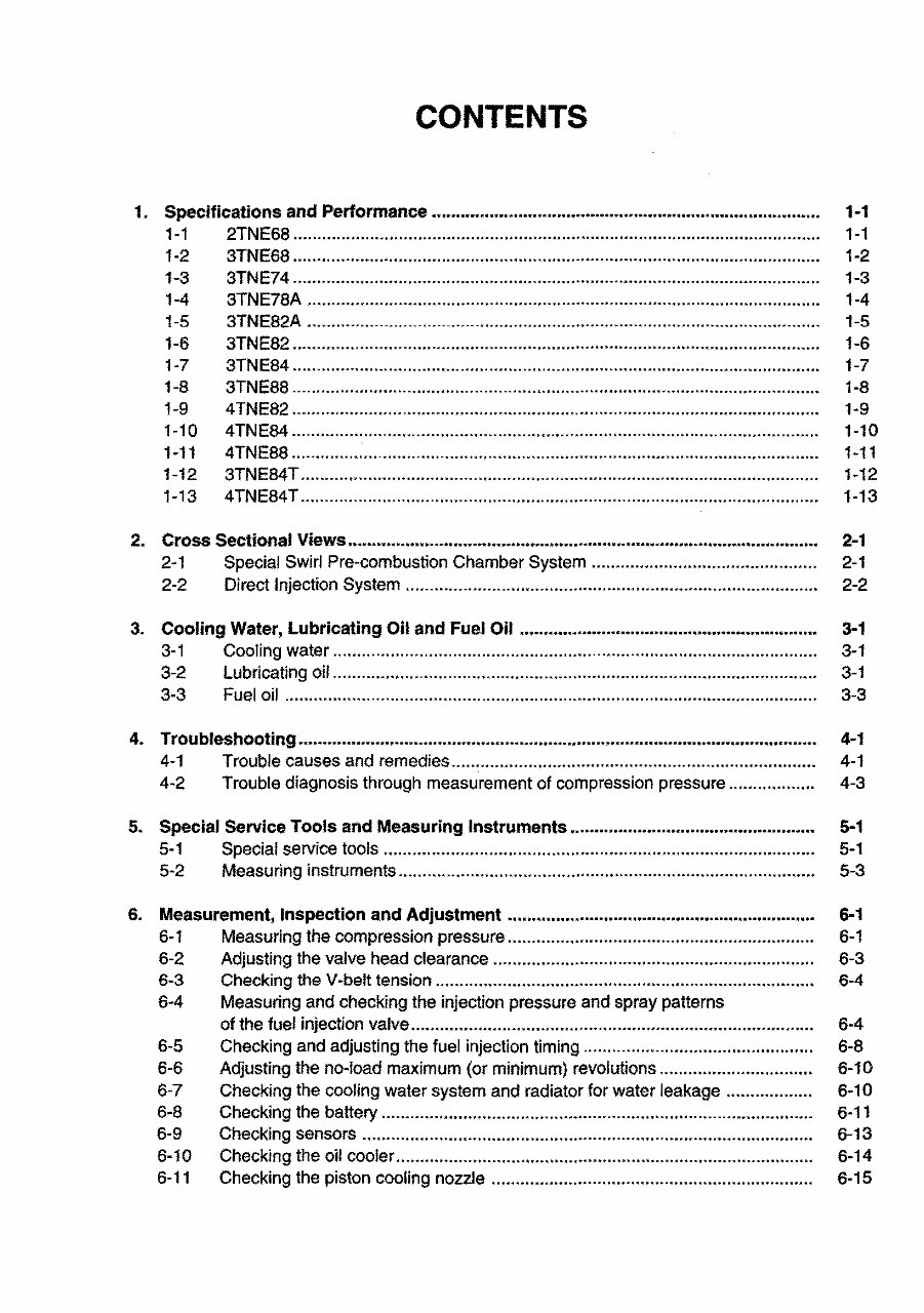
CONTENTS 1. Specifications and Performance •..• ................... •.•...•.• ..... •••• .... •••.•.• ........... • ....... •.•...•.•. 1-1 1-1 2TNE68.............................................................................................................. 1-1 1-2 3TNE68 .... .... ....................... ...................... ......................................................... 1-2 1-3 3TNE74 .............................................................................................................. 1-3 1-4 3TNE78A .. ................................. ........ ............ .......................... ........ .......... ........ 1-4 1-5 3TNE82A ........................................................................................................... 1-5 1-6 3TNE82 .............................................................................................................. 1-6 1-7 3TNE84.............................................................................................................. 1-7 1-8 3TNE88 .............................................................................................................. 1-8 1-9 4TNE82.............................................................................................................. 1-9 1-10 4TNE84.............................................................................................................. 1-10 1-11 4TNE88.............................................................................................................. 1-11 1-12 3TNE84T............................................................................................................ 1-12 1-13 4TNE84T............................................................................................................ 1-13 2. Cross Sectional Views ................. • ......... ••.•..•••.•••...• ........... • ....... •...••••• .... •...•...• ..... • ..... •. 2-1 2-1 Special Swirl Pre-combustion Chamber System ............................................... 2-1 2-2 Direct Injection System.......... ................................ ...... ........ .............................. 2-2 3. Cooling Water, Lubricating Oil and Fuel Oil .............................................................. 3-1 3-1 Cooling water ..................................................................................................... 3-1 3-2 lubricating oil........................................ ............................................................. 3-1 3-3 Fuel oil .................... ............. .............. .............. .............. ..... ............................... 3-3 4. Troubleshooting ............................................................................................................ 4-1 4-1 Trouble causes and remedies............................................................................ 4-1 4-2 Trouble diagnosis through measurement of compression pressure .................. 4-3 5. Special Service Tools and Measuring Instruments ................................................... 5-1 5-1 Special service tools.......... ...................... ..................... .................... ............ ..... 5-1 5-2 Measuring instruments ....................................................................................... 5-3 6. Measurement, Inspection and Adjustment ................................................................ 6-1 6-1 Measuring the compression pressure ......... ................. ................ .......... ............ 6-1 6-2 Adjusting the valve head clearance .................. ................................................. 6-3 6-3 Checking the V -belt tension ...... ............................. ................ ............................ 6-4 6-4 Measuring and checking the injection pressure and spray patterns of the fuel injection valve ........................................... ........................... .............. 6-4 6-5 Checking and adjusting the fuel injection timing ................................................ 6-8 6-6 Adjusting the no-load maximum (or minimum) revolutions ................................ 6-10 6-7 Checking the COOling water system and radiator for water leakage .................. 6-10 6-8 Checking the battery ............................. ............................................................. 6-11 6-9 Checking sensors .............................................................................................. 6-13 6-10 Checking the oil cooler ....................................................................................... 6-14 6-11 Checking the piston cooling nozzle ................................................................... 6-15
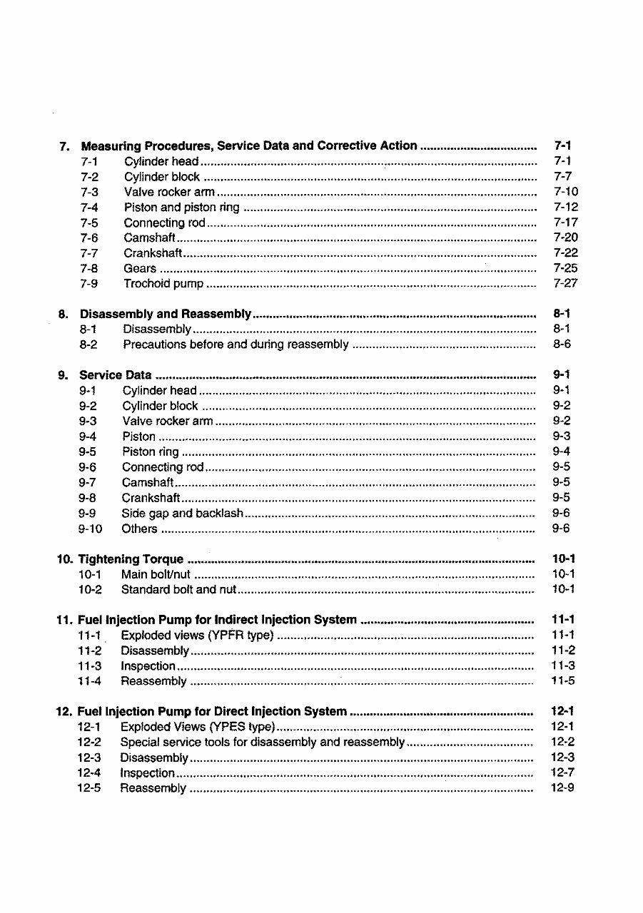
7. Measuring Procedures, Service Data and Corrective Action ................................... 7-1 7-1 Cylinder head ... ...... ........•......... ...... ...................... ........ ........ ... ........... ........ ........ 7-1 7-2 Cylinder block .................................................................................................... 7-7 7-3 Valve rocker arm..... ........ ...... .......... ...... .............. ............................................... 7-10 7-4 Piston and piston ring ...... ...................... .......................................... .................. 7-12 7·5 Connecting rod................ ............ .......... ............. ............. ................................... 7-17 7-6 Camshaft............................................................................................................ 7-20 7-7 Crankshaft.......................................................................................................... 7-22 7-8 7-9 Gears ................................................................................................................. Trochoid pump ................................................................................................. .. 8. Disassembly and Reassembly ..................................................................................... 8-1 Disassembly ....................................................................................................... 8-2 Precautions before and during reassembly ..................................................... .. 9. Service Data ................................................................................................................. . 9-1 Cylinder head ................................................................................................... .. 9-2 Cylinder block .................................................................................................... 9-3 Valve rocker arm ................................................................................................ 9-4 Piston ................................................................................................................ . 9-5 Piston ring ........................................................................................................ .. 9-6 Connecting rod ................................................................................................. .. 9-7 Camshaft ............................................................................................................ 9-8 Crankshaft ........................................................................................................ .. 7·25 7-27 8-1 8-1 8-6 9-1 9·1 9-2 9·2 9-3 9-4 9-5 9-5 9-5 9-9 Side gap and backlash ....................................................................................... 9-6 9-1 0 Others ................................................................................................................ 9-6 10. Tightening Torque ........................................................................................................ 10-1 10-1 Main bolVnut ...................................................................................................... 10-1 10-2 Standard bolt and nut.. .................. ...... ..................... .......................................... 10-1 11. Fuel Injection Pump for Indirect Injection System .................................................... 11-1 11·1 Exploded views (YPFR type) .. ........ ........ ................ ..... ............ ........ ..... ... ...... .•.. 11-1 11-2 Disassembly ....................................................................................................... 11-2 11·3 Inspection......... .................................................................................................. 11-3 11-4 Reassembly .............................. ................... ................. ........... ............. ............. 11-5 12. Fuel Injection Pump for Direct Injection System ....................................................... 12-1 12-1 Exploded Views (YPES type)............................................................................. 12·1 12-2 Special service tools for disassembly and reassembly.... .................................. 12·2 12-3 Disassembly.......................... ........ ..................................................................... 12-3 12-4 Inspection........................................................................................................... 12-7 12-5 Reassembly .......................................................... ......................... ........ ...... ...... 12·9
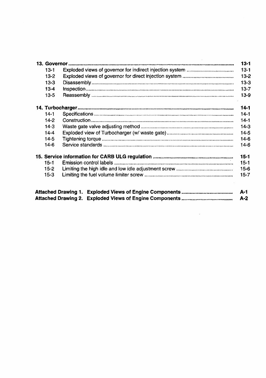
13. Governor ................................................................................................. ....................... 13·1 13-1 Exploded views of governorfor indirect injection system ... ............................... 13-1 13-2 Exploded views of governor for direct injection system ..................................... 13-2 13-3 Disassembly................ ............................. ..... .... .......................... ..... ........... ....... 13-3 13-4 Inspection........................................................................................................... 13-7 13-5 Reassembly.... ....... ...... ...... .................... ........ ........... ................. ................ .... .... 13-9 14. Turbocharger ................................................................................................................. 14·1 14-1 Specifications ..................................................................................................... 14·1 14-2 Construction ....................................................................................................... 14-1 14-3 Waste gate valve adjusting method .... .... .... ........ ...... .... ................ ..... ......... ....... 14-3 14·4 Exploded view of Turbocharger (wI waste gate) .. ... ........ .... .... ............ .......... ..... 14-5 14-5 Tightening torque ............................. ................ ........... ............ ........................... 14-6 14-6 Service standards .............................................................................................. 14-6 15. Service Information for CARS ULG regulation .......................................................... 15·1 15-1 Emission control labels ................................................................................... :.. 15-1 15-2 Limiting the high idle and low idle adjustment screw......................................... 15-6 15-3 Limiting the fuel volume limiter screw.... ............................................................ 15-7 Attached Drawing 1. Exploded Views of Engine Components ..................................... A·1 Attached Drawing 2. Exploded Views of Engine Components ..................................... A·2
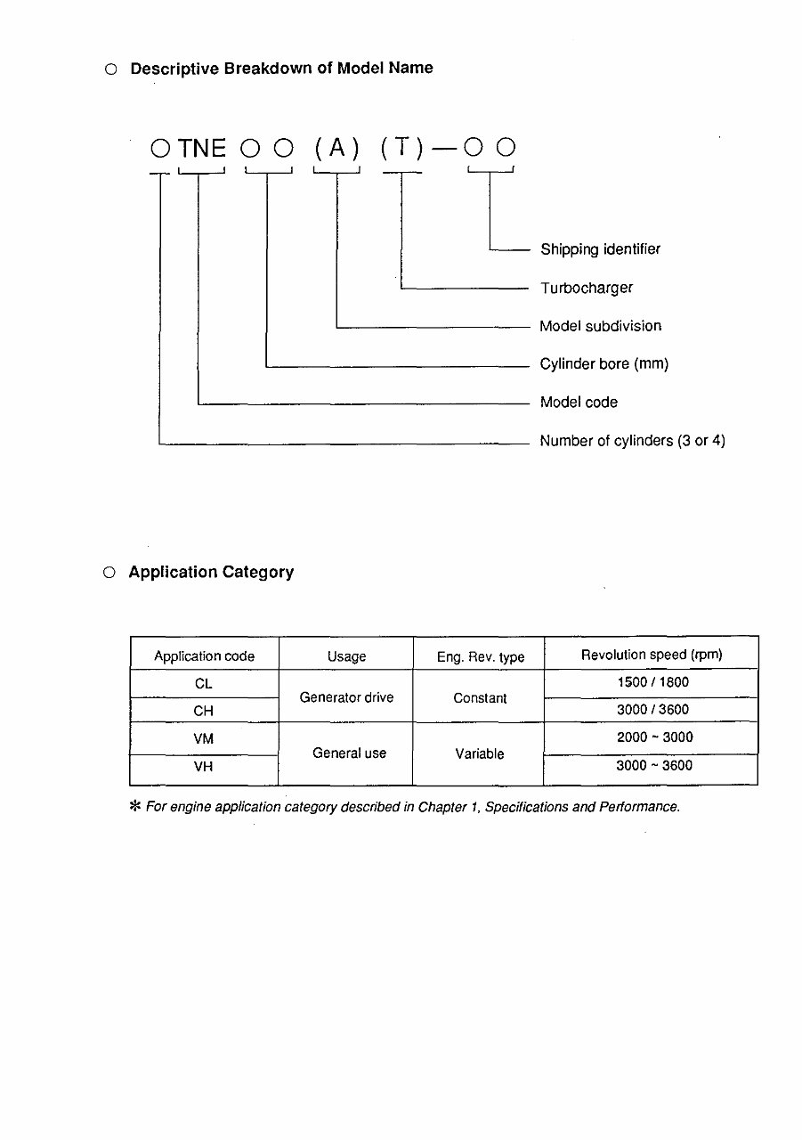
o Descriptive Breakdown of Model Name o TN E 0 0 (A) (T) - 0 0 -,- '------. Shipping identifier Turbocharger L-_________ Model subdivision Cylinder bore (mm) Model code Number of cylinders (3 or 4) o Application Category Application code Usage Eng. Rev. type Revolution speed (rpm) CL 1500/1800 Generator drive Constant CH 3000/3600 VM 2000 ~ 3000 General use Variable VH 3000 ~ 3600 * For engine application category described in Chapter 1. Specifications and Performance.
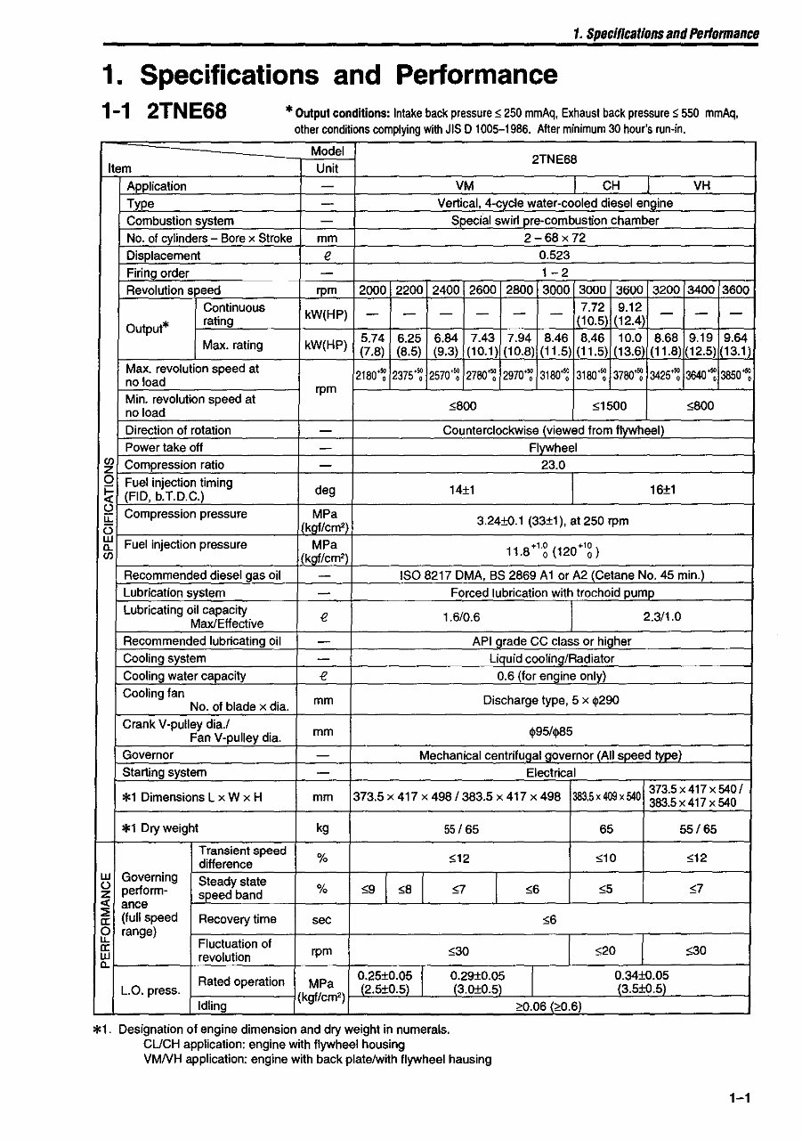
1. Specifications and Performance 1. Specifications and Performance 1-1 2TNE68 * Output conditions: Intake back pressure $ 250 mmAq, Exhaust back pressure $ 550 mmAq, other conditions complying with JIS 0 1005-1986. After minimum 30 hour's run·in. Model 2TNE68 Item Unit Application - VM I CH VH Type - Vertical, 4·cycle water·cooled diesel engine Combustion system - Special swirl pre·combustion chamber No. of cylinders - Bore x Stroke mm 2-68x72 Displacement e 0.523 Firing_order - 1-2 Revolution speed rpm 2000 2200 2400 2600 2800 3000 3000 3600 3200 3400 3600 Continuous kW(HP) - - - - - - 7.72 9.12 - - - Output* rating (10.5) (12.4) 5.74 6.25 6.84 7.43 7.94 8.46 8,46 10.0 8.68 9.19 9.64 Max. rating kW(HP) (7.8) (8.5) (9.3) (10.1 ) (10.8) (11.5) (11.5) (13.6) (11.8) (12.5) (13.1 ) Max. revolution speed at 2180'~ 2375'~ 2570'~ 2780+~ 2970'~ 3180+~ 3180'~ 3780+~ 3425'~ 3640~ 3850+~ no load Min. revolution speed at rpm no load 5800 51500 5800 Direction of rotation - Counterclockwise (viewed from flywheel) Power take off - Flywheel en Compression ratio z - 23.0 0 Fuel injection timing ~ (FlO, b.T.D.C.) deg 14±1 16±1 C,) Compression pressure MPa u:: 3.24±O.1 (33±1), at 250 rpm i3 IlkQficm" w Fuel injection pressure MPa 11.8·'g (120·'g) 0.. en .Ikgf/cm') Recommended diesel gas oil - ISO 8217 DMA, BS 2869 AI or A2 (Cetane No. 45 min.) Lubrication system - Forced lubrication with trochoid pump Lubricating oil capacity e 1.6/0.6 2.311.0 Max/Effective Recommended lubricating oil - API grade CC class or higher Cooling system - Liquid coolinglRadiator Cooling water capacity e 0.6 (for engine only) Cooling fan mm Discharge type, 5 x $290 No. of blade x dia. Crank V·pulley dia.l mm $95/$85 Fan V·pulley dia. Governor - Mechanical centrifugal governor (All speed ty~ Starting system - Electrical *1 DimenSions L x W x H 373.5 x 417 x 498/383.5 x 417 x 498 383.5 x 409 x 540 373.5 x 417 x 540 I mm 383.5x417 x 540 *1 Dry weight kg 55/65 65 55/65 Transient speed % $12 510 512 difference w Governing Steady state 59 I 58 I C,) perform· % 57 56 $5 $7 z speed band <{ ance ~ (full speed Recovery time 56 a: sec 0 range) u. Fluctuation of a: rpm 530 520 530 w revolution 0.. I Rated operation MPa 0.25±0.05 0.29±0.05 O.34±O·~r L.a. press. (2.5±O.5) (3.0±0.5) (3.5±O.5 Idling (kgf/cm') ,,0.06 (;>0.6) *1. Designation of engine dimension and dry weight in numerals. CUCH application: engine with flywheel housing VMNH application: engine with back plateiwith flywheel hausing 1-1
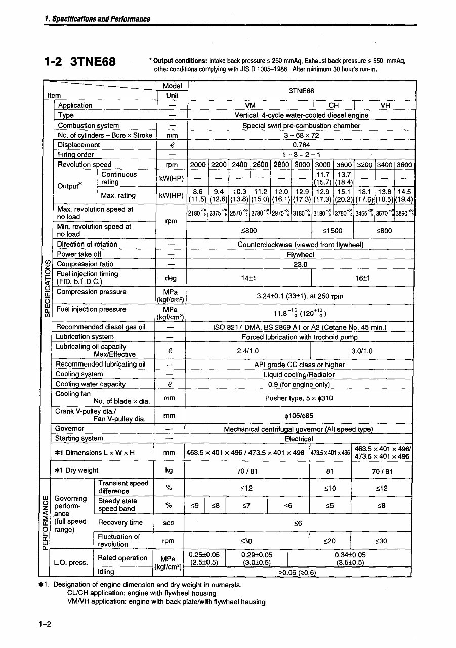
1. Specificallons and Performance 1-2 3TNE68 • Output conditions: Intake back pressure ~ 250 mmAq, Exhaust back pressure ~ 550 mmAq, other conditions complying with JIS D 1005-1986. After minimum 30 hour's run-in. Model 3TNE68 Item Unit Application - VM CH T VH Type - Vertical, 4-cvcle water-cooled diesel en!line Combustion svstem - Special swirl pre-combustion chamber No. of cvlinders - Bore x Stroke mm 3-68x72 Displacement € 0.784 Firing order - 1-3-2-1 Revolution speed rpm 2000 2200 2400 2600 2800 3000 3000 3600 3200 3400 3600 Continuous kW(HP) - - - - - - 11.7 13.7 - - - Output* rating (15.7) (18.4) Max. rating kW(HP) 8.6 9.4 10.3 11.2 12.0 12.9 12.9 15.1 13.1 13.8 14.5 (11.5) (12.6) (13.8) (15.0) (16.1) (17.3) (17.3) (20.2 (17.6) (18.5) (19.4) Max. revolution speed at 2180": 2375 ": 2570": 2780 ": 2970": 3180": 3180'~ 3780'~ 3455'~ 3670 ": 3890 ": no load Min. revolution speed at rpm no load $800 $1500 $800 Direction of rotation - Counterclockwise (viewed from flywheel) Power take off - Flywheel Ul Compression ratio - 23.0 z 0 Fuel injection timing ~ (FlO, b.T.D.C.) deg 14±1 16±1 u Compression pressure MPa u: 3.24±0.1 (33±1), at 250 rpm 5 (kaf/cm') w Fuel injection pressure MPa 11.8+'~ (120+'g) Il. Ul (kaf/cm') Recommended diesel gas oil - ISO 8217 DMA, BS 2869 AI or A2 (Cetane No. 45 min.) Lubrication system - Forced lubrication with trochoid pump Lubricating oil capacity € 2.4/1.0 3.0/1.0 Max/Effective Recommended lubricating oil - API !lrade CC class or higher Cooling system - Liquid coolinglRadiator Cooling water capacity € 0.9 (for engine only) Coolingfan mm Pusher type, 5 x $310 No. of blade x dia. Crank V-pulley dia.! mm $105/$85 Fan V-pulley dia. Governor - Mechanical centrifugal governor (All speed type) Starting system - Electrical *1 Dimensions Lx W x H 463.5 x 401 x 496 I 473.5 x 401 x 496 473.5x401 x 496 463.5 x 401 x 4961 mm 473.5 x 401 x 496 *1 Dry weight kg 70/81 81 70/81 Transient speed % $12 SID s12 difference w Governing Steady state $9 I $8 I I u perform- % 57 $6 $5 $8 z sDeed band « ance ::;; (full speed Recovery time $6 a: sec 0 range) "- Fluctuation of a: rpm :>30 :>20 $30 w revolution Il. Rated operation MPa ~.25±0.~~ I ~:29±O.~~ I ~:34±0.~~ L.O. press. 2.5±O.5 3.0±0.5 3.5±O.5 Idling (kgf/em') >0.06 (?0.6)- *1. Designation of engine dimension and dry weight in numerals. CUCH application: engine with flywheel housing VMNH application: engine with back platelwith flywheel hausing 1-2
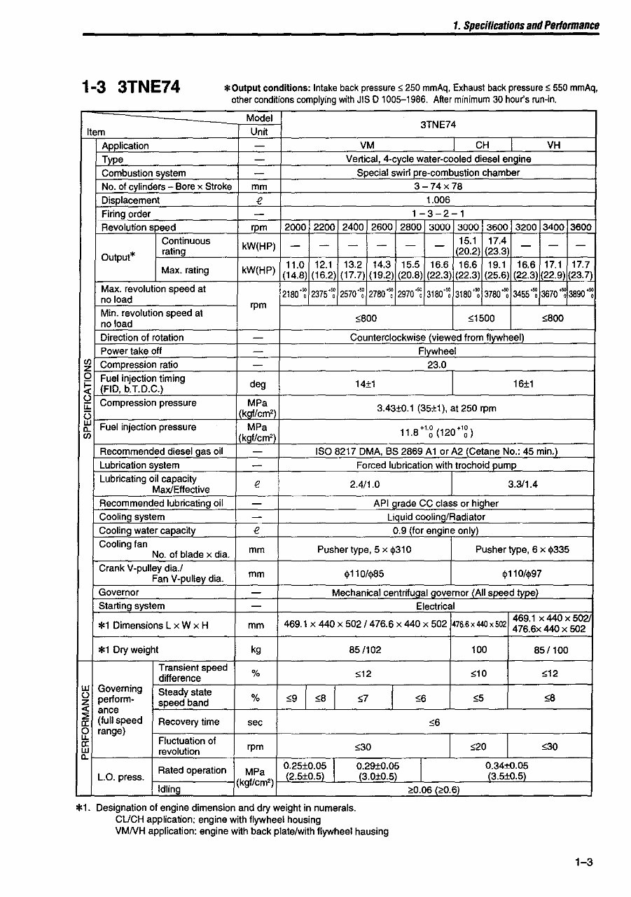
1. Specifications and Performance 1-3 3TNE74 *Output conditions: Intake back pressure ~ 250 mmAq, Exhaust back pressure ~ 550 mmAq, other conditions complying with JIS 0 1005-1986. After minimum 30 hour's run·in. Model 3TNE74 Item Unit Application - VM CH ~ VH Type - Vertical, 4·cycle water·cooled diesel engine Combustion system - Special swirl pre·combustion chamber No. of cylinders - Bore x Stroke mm 3-74x78 Displacement f! 1.006 Firing order - 1-3-2-1 Revolution speed rpm 2000 2200 2400 2600 2800 3000 3000 3600 3200 3400 3600 Continuous kW(HP) - - - - - - 15.1 17.4 - - - Output* rating (20.2) (23.3) 11.0 12.1 13.2 14.3 15.5 16.6 16.6 19.1 16.6 17.1 17.7 Max. rating kW(HP) (14.8) (16.2) (17.7) (19.2) (20.8) (22.3) (22.3) (25.6) (22.3) 22.9 (23.7) Max. revolution speed at 2180+~ 2375'~ 2570'~ 2780": 2970'~ 3180": 3180'~ 3780": 3455~ 3670": 3890~ no load Min. revolution speed at rpm no load ~800 ~1500 ~800 Direction of rotation - Counterclockwise (viewed from flywheel) Power take off - Flywheel (/) Compression ratio z - 23.0 0 Fuel injection timing ~ (FlO, b.T.D.C.) deg 14±1 16±1 () Compression pressure MPa iL: 3.43±O.1 (35±1), at 250 rpm (3 (kgf/cm') UJ Fuel injection pressure MPa 11.8·'g (120·'g) "- (/) kgf/cm') Recommended diesel gas oil - ISO 8217 DMA, BS 2869 Alar A2 (Cetane No.: 45 min.) Lubrication system - Forced lubrication with trochoid pump Lubricating oil capacity f! 2.411.0 3.311.4 Max/Effective Recommended lubricating oil - API grade CC class or higher Cooling system - Liquid coolinQ/Radiator Coolil1g water capacity f! 0.9 (for engine only) Cooling fan mm Pusher type, 5 x ~310 Pusher type, 6 x ~335 No. of blade x dia. Crank V·pulley dia.! mm ~110/<1>8S ~110/~97 Fan V·pulley dia. Governor - Mechanical centrifugal governor LAII speed type) Starting system - Electrical *1 Dimensions L x W x H 469.1 x 440 x S02/476.6 x 440 x S02 476.6 x 440 x 502 469.1 x 440 x S021 mm 476.6x 440 x 502 *1 Dry weight kg 8SI102 100 8SI100 Transient speed % $12 $10 ,;12 difference UJ Governing Steady state ,,9 I ,,8 I () perform· % ,;7 ,,6 "S ,,8 z speed band ..: ance ~ (full speed Recovery time ,,6 0: sec rr range) 0: Fluctuation of ,,30 ,;20 ,,30 UJ revolution rpm "- Rated operation MPa ~:2S±0.~~ I 0.29±O.05 1 0.34±O.OS L.O. press. 2.S+0.S . (3.0±O.S) (3.S±O.S) Idling (kgf/cm') >0.06 (;'0.6) *1. Designation of engine dimension and dry weight in numerals. CUCH application: engine with flywheel housing VMNH application: engine with back plate/with flywheel hausing 1-3
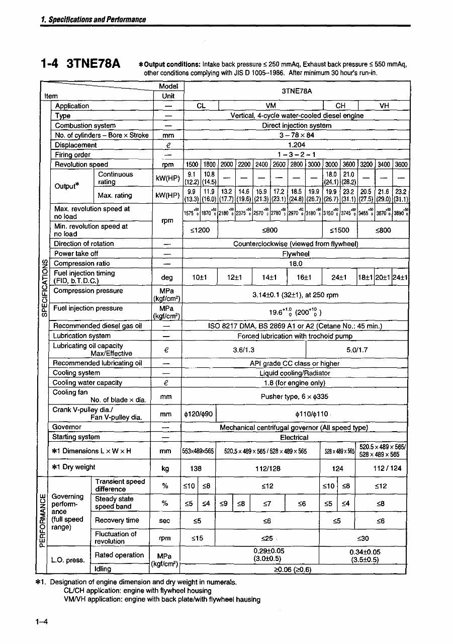
1. Specincations and Performance 1-4 3TNE78A * Output conditions: Intake back pressure ~ 250 mmAq, Exhaust back pressure ~ 550 mmAq, other conditions complying with JIS D 1005-1986. After minimum 30 hou(s run-in. Model 3TNE78A item Unit Application - CL VM I CH VH Type - Vertical, 4-cycle water-cooled diesel engine Combustion system - Direct injection system No. of cylinders - Bore x Stroke mm 3-78x84 Displacement t! 1.204 Firing order - 1-3-2-1 Revolution speed rpm 1500 1800 2000 2200 2400 2600 2800 3000 3000 3600 3200 3400 3600 Continuous kW(HP) 9.1 10.8 - - - - - - 18.0 21.0 - - - Output* rating (12.2) (14.5) (24.1) (28.2) Max. rating kW(HP) 9.9 11.9 13.2 14.6 15.9 17.2 18.5 19.9 19.9 23.2 20.5 21.6 23.2 (13.3 (16.0) (17.7) (19.6) (21.3) (23.1) (24.8) (26.7) (26.7) (31. t) (27.5) (29.0) (31.1) Max. revolution speed at 1575~ 1870~ 2180~ 2375'~ 2570'~ 2780~ ,. 3180'~ 3150~ 3745~ .., 3670~ 3800+~ no load 2970 0 3455 , Min. revolution speed at rpm no load ~1200 ~800 ~1500 ~800 Direction of rotation - Counterclockwise (viewed from fly~heel) Power take off - Flywheel en Compression ratio z - 18.0 0 Fuel injection timing ~ (FID, b.T.D.C.) deg 10±1 12±1 14±1 16±1 24±1 18±1 20±1 24±1 () Compression pressure MPa u:: 3.14±O.1 (32±1), at 250 rpm U (kgf/cm') w Fuel injection pressure MPa a. 19.6+'g (200+'g ) en I (kgf/cm') Recommended diesel gas oil - ISO 8217 DMA, BS 2869 Al or A2 (Cetane No.: 45 min.) Lubrication system - Forced lubrication with trochoid pump Lubricating oil capacity t! 3.6/1.3 5.0/1.7 Max/Effective Recommended lubricating oil - API grade CC class or higher Cooling system - Liquid cooling/Radiator Cooling water capac~y t! 1.8 (for engine only) Cooling fan mm Pusher type, 6 x ~335 No. of blade x dia. Crank V-pulley dia.! mm ~120/~90 ~110/~110 Fan V-pulley dia. Governor - Mechanical centrifuQal Qovernor (All speed type) Starting system - Electrical *1 Dimensions L x W x H mm 553x489x565 520.5 x 489 x 565/528 x 489 x 565 528 x 4a9 x 565 520.5 x 489 x 565/ 528 x 489 x 565 *1 Dry weight kg 138 1121128 124 112/124 Transient speed % S10 S8 ~12 ~10 ~8 ,,12 difference w Governing Steady state ,,91 S8 1 1 () perform- % ,,5 S4 g ,,6 S5 S4 s8 z speed band c( ance ::0 (full speed Recovery time ,,5 ~6 ,,5 ,,6 cr: sec 0 range) "- Fluctuation of cr: S15 525· S30 w revolution rpm a. Rated operation 0.29±O.05 O.34±O.OS L.O. press. MPa (3.0±0.5) (3.S±O.5) Idling (kgf/cm') >0.06 (?0.6) *1. Designation of engine dimension and dry weight in numerals. CUCH application: engine with flywheel housing VMNH application: engine with back plateiwith flywheel hausing 1-4
The Complete Factory Service Repair Workshop Manual is a comprehensive guide designed to assist with repair, servicing, and troubleshooting needs. It includes hundreds of pages with precise photos and diagrams, providing step-by-step instructions and detailed exploded diagrams and pictures. This manual is trusted by professional mechanics and technicians and is useful for both professional mechanics and DIY enthusiasts.
Common Questions:
Q. Can I print out a page?
A. Yes, you have the freedom to print out a single page or the entire manual, depending on your preference.
Q. Can I use this Manual on multiple computers?
A. Yes, you can use this manual on as many computers as you need, making it convenient for workshops or multiple users.
Q. Is this a trial or limited version?
A. No, this is the FULL Manual without any limitations or trial periods. You have unrestricted access to all its content for a lifetime.
Q. Will this Manual expire or require renewal fees?
A. Not at all! You can enjoy using this manual for life without any expiration or renewal fees. It's a one-time investment.
Q. Will this Manual work on both Windows and MAC computers?
A. Yes, it is fully compatible with all Windows and MAC computers, ensuring seamless usage across different platforms.
To access this invaluable resource, simply click the button below. Enhance your repair skills with this comprehensive manual.
Recently Viewed
5,521,897Happy Clients
2,594,462eManuals
1,120,453Trusted Sellers
15Years in Business
Price:
Actual Price:
YANMAR 4TNE84 4TNE88 3TNE84T 4TNE84T Engine Full Service & Repair Manual