

Wisconsin Engine Repair Manual for TJD,THD,TH engines
What's Included?
Fast Download Speeds
Online & Offline Access
Access PDF Contents & Bookmarks
Full Search Facility
Print one or all pages of your manual
WISCONSIN
MODE~ W2-880
TJD, THD, TH
REPAIR
]~CORP.
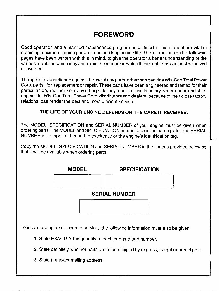
FOREWORD
Good operation anda planned maintenance program as outlined in this manual are vital in
obtaining maximum engine performance andlong engine life. Theinstructions on the following
pages have been written with this in mind,to give the operatora better understanding of the
various problems which may arise, andthe manner in which these problems can best be solved
or avoided.
The operator is cautioned againstthe useof anyparts, other than genuine Wis-Con Total Power
Corp.parts, for replacement or repair. These parts have been engineered and tested for their
particular job, and the useof any other parts may result in unsatisfactory performance and short
engine life. Wis-Con Total Power Corp. distributors and dealers, because of their close factory
relations, canrender the best and most efficient service.
THE LIFE OF YOUR ENGINE DEPENDS ON THE CARE IT RECEIVES.
The MODEL, SPECIFICATION and SERIAL NUMBER of your engine must be given when
ordering parts. The MODEL and SPECIFICATION number are on the name plate. The SERIAL
NUMBER is stamped either on the crankcase or the engine’s identification tag.
Copy the MODEL, SPECIFICATION and SERIAL NUMBER in the spaces provided below so
that it will be available when ordering parts.
MODEL SPECIFICATION
SERIAL NUMBER
To insure prompt and accurate service, the following informationmust also be given:
1. State EXACTLY the quantity of eachpart andpart number.
2. State definitely whether parts are to be shipped by express, freight or parcel post.
3. State the exactmailing address.
IMPORTANT
READTHESE INSTRUCTIONS CAREFULLY
All pointsof operation and maintenance have been covered as carefully as possible,but if further
information is required, send inqt,~iries to the factoryfor prompt attention.
When writing to the factory, ALWAYS GIVE THEMODEL, SPECIFICATION AND SERIAL
NUMBER of the enginereferred to.
Starting and Operating New Engines
Careful breaking-in of a new engine will greatly increase its life and result in troublefree operation.
A factory test is not sufficient to establish the polished bearing surfaces, which are so necessary
to the proper performance and long life of an engine.These can only be obtained by runninga
new engine carefully and under reduced loadsfor a short time.
¯ Be surethe engine is filled to the proper level with a good quality engine oil.
¯ For proper procedures to follow when breaking-in a new engine, see’Testing Rebuilt Engine’.
The various bearing surfaces in a new engine have not been glazed, asthey will be with continued
operation, and it is in this period of "running in" that specialcaremust be exercised, otherwise
the highly desired glaze will neverbe obtained. A new bearing surface that has once been
damaged by carelessness will be ruined forever.
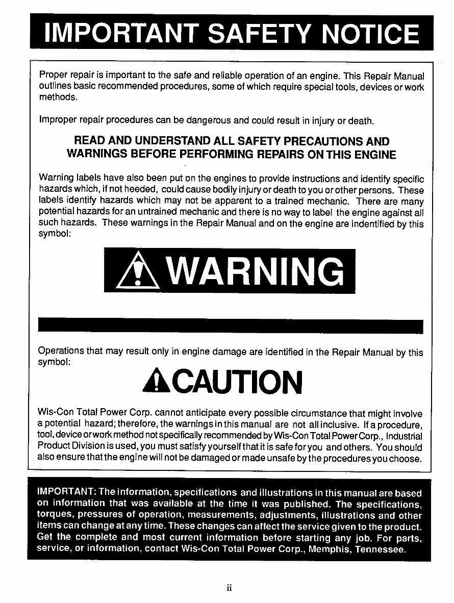
IMPORTANT SAFETY NOTICE
Proper repair is important to the safe and reliable operation of an engine. This Repair Manual
outlines basic recommended procedures, some of whichrequire special tools, devicesor work
methods.
Improper repair procedures canbe dangerous and could result in injury or death.
READAND UNDERSTAND ALL SAFETY PRECAUTIONS AND
WARNINGS BEFORE PERFORMING REPAIRS ON THIS ENGINE
Warning labels have also been put on the engines to provide instructions and identify specific
hazards which, if not heeded, couldcause bodily injury or death to youor other persons. These
labels identify hazards which may not be apparentto a trained mechanic. Thereare many
potential hazards for an untrained mechanic and there is no way to label the engine againstall
such hazards. These warnings in the RepairManual andon the engine are indentified by this
symbol:
z WARNING
Operations that may result only in engine damage are identified in the RepairManual by this
symbol:
&CAUTION
Wis-Con Total Power Corp. cannot anticipate every possible circumstance that mightinvolve
a potential hazard; therefore,the warnings in this manual are not all inclusive. If a procedure,
tool, device orwork method not specifically recommended by Wis-Con Total PowerCorp., Industrial
Product Divisionis used, you must satisfy yourselfthat it is safe for you and others.You should
also ensure that the engine will not be damaged or made unsafe by the procedures youchoose.
IMPORTANT: The information, specifications and illustrations in this manual are based
on informationthat was available at the time it was published.The specifications,
torques, pressures of operation, measurements, adjustments, illustrations and other
items can change at any time. These changes can affect the service given to the product.
Get the complete and most current information before starting any job. For parts,
service, or information, contact Wis-Con Total Power Corp., Memphis, Tennessee.
/ WARNING
Mostsub-systems usedin conjunction with Wis-Con Total Power Corp. industrial engines
including (but not limited to) radiators, hoses, fans, fuel tanks,fuel lines or otherfuel system
components, batteries, electrical connections or other electrical components, clutches, trans-
missions, hydraulic pumps and generators, are not supplied by Wis-Con Total Power Corp.
These items are provided by the manufacturer of the end item in which the engine is used.
Some of the dangers associatedwith servicing such items are generally mentioned in this
manual; however, the appropriate handbooks and safety instructions provided by the manufac-
turer of the end item should always be consulted prior to the undertaking of anyworkon sub-
systems attached to the engine, to avoid any hazards inherent to thesesub-systems.
Read and observe all individual safety warnings as youusethis manual to operate, service or
repair your engine.
Always exercise caution whenever working with an engine or any associated system.
Injuries may be caused by lack of care when working with, or near, moving parts, hot parts,
pressurized systems, electrical equipment, or fuel systems.
Always weareye andhearing protection when working on or near engines.
Improper attire such as loose clothing,ties, rings, soft shoes or bare feet could be hazardous and
should be avoided when servicing engines.
Use or serviceof the engine (includingthe use of modified parts or materials) not in accordance
with manufacturer’s specifications could damage your engine or cause personal injury.
/ WARNING
Some equipment andmaterials usedin the overhaul or maintenance of an engine such as
machine tools, electrical equipment, compressed air, solvents, gasoline or other fuels may be
dangerous andcan cause injury. Always observe safety precautions.
ooo
111
Safety
Precautions
¯ Never fill fuel tank while engine is running or hot;
avoid the possibility of spilled fuel causing a fire.
¯ Always refuel slowly to avoid spillage.
¯ When starting engine, maintain a safe distance from
moving parts of equipment.
¯ Do not start engine with clutch engaged.
¯ Do not spin hand crank when starting. Keep crank-
ing components clean and free from conditions
which might cause the crank jaw to bind and not re-
lease properly. Oil periodically to prevent rust.
¯
Never run engine with governor disconnected, or op-
erate at speeds in excess of 3600 R.P.M. load.
Do not operate engine in a closed building unless
the exhaust is piped outside. This exhaust contains
carbon monoxide, a poisonous, odorless and invi-
sible gas, which if breathed causes serious illness
and possible death.
Never make adjustments on machinery while it is
connected to the engine, without first removing the
ignition cables from the spark plugs. Turning the
machinery over by hand during adjusting or cleaning
might start the engine and machinery with it, caus-
ing serious injury to the operator.
¯
Precaution is the best insurance agvinst accidents.
Keep this book handy at all times, fami-
liarize yourself with the operating instructions.
CONTENTS
Air Cleaners ....................................................................
10
Dry .Element (Tri-Phase) Air Cleaner .......................
11
Dry Type Air Cleaner ................................................
11
Oil Bath Air Cleaner .................................................
10
Alternator -- Flywheel ...................................................
17
Battery Ignition -- Distributor .......................................
14
Breather -- Crankcase ....................................................
11
Carburetor Adjustment ....................................................
12
Carburetor Service
Walbro Model LMH-33 .............................................
37
Walbro Model LUB ...................................................
35
Walbro Model WHG-53 ............................................
39
Zentih Model 68-7 ..................................................... 33
Clutch Adjustment ..........................................................
19
Clutch Power Take-off ...................................................
19
Clutch Reduction Unit Adjustment ................................
20
Compression -- Restoring ..............................................
17
Cooling ............................................................................. 8
Disassembly and Reassembly .........................................
22
Accessories ................................................................
22
Camshaft ....................................................................
28
Camshaft Gear ...........................................................
25
Carburetor and Manifold ...........................................
24
Connecting Rod and Piston .......................................
25
Crankshaft and Main Bearing Plate..........................
27
Cylinder Block .......................................................... 27
Cylinder Head ............................................................ 24
Engine Base ............................................................... 25
Flywheel and Shroud .................................................
23
Fuel Tank ...................................................................
24
Gear Cover ................................................................
24
House Panels .............................................................
22
Oil Pump ...................................................................
25
PistonRing and Rod Clearance Chart .......................
26
Piston Rings ...............................................................
26
Valve Tappets ............................................................
28
Valves and Seat Inserts .............................................
27
Distributor and Generator Maintenance .........................
15
Electric Wiring Circuits ..................................................
15
Electrical Wiring Diagrams ............................................
16
Firing Order .................................................................... 14
Flywheel Alternatorwith Solid State Regulation ...........
30
Fuel ................................................................................... 9
Fuel Filter ........................................................................
11
Fuel Pump & Priming ........................................................ 9
Fuel Pump Service .....................................................
~ .....
29
Gear Train --Timing Marks (Fig. 36) ...........................
25
General Information and Design ......................................
8
Governor Adjustment .....................................................
18
Governor Operation .....................................................
:.. 18
Horsepower .......................................................................
8
Ignition Switch ..................................................................
9
Ignition System .................................................................
8
Illustrations, Engine
Cross Section (TJD) ....................................................
6
Fan End View (W2-880) .............................................
5
Lubrication System (TJD) ...........................................
7
Power Unit Fan End View (TJD) ................................
4
Take-off View (TJD) ...................................................
3
Take-off View (W2-880) .............................................
5
Lubrication ........................................................................
8
Lubrication System ...........................................................
8
Magneto Breaker PointAdjustment ...............................
12
Magneto Ignition Spark ..................................................
12
Magneto Service
Fairbanks-Morse (Type FMX2B7E) .........................
42
Fairbanks-Morse (Type FMX 12B71) .......................
43
Wico Model XH-2D ..................................................
41
Magneto Timing .............................................................
13
Magneto Timing Diagram ..............................................
13
Maintenance Section .......................................................
10
Oil-- Grade of and Service Classification ......................
9
Oil Spray Nozzles ...........................................................
28
Reduction Gears ..............................................................
20
Rotation ............................................................................
8
Safety Precautions ............................................................
1
Safety Switch - High Temperature .................................
17
Solid State Ignition Distributors .....................................
16
Spark Plugs .....................................................................
17
Starting and Operating Instructions ..................................
8
Starting and Operating New Engines ................................
i
Starting Procedure ..........................................................
10
Stopping Engine ..............................................................
10
Storage of Engine forWinter ..........................................
20
Testing Rebuilt Engine ...................................................
22
Timing
Distributor Timing .....................................................
14
Magneto Timing ........................................................
13
Neon Lamp Timing ...................................................
15
Troubles -- Causes and Remedies .................................
20
Backfiring Through Carburetor .................................
22
Compression ..............................................................
21
Ignition ......................................................................
21
Knocking ...................................................................
22
Missing ...................................................................... 21
Overheating ...............................................................
22
Starting Difficulties - Fuel Mixture ...........................
21
S tops ..........................................................................
21
Surging or Galloping .................................................
21
Valves --Grinding ..........................................................
27
Valve Tappet Adjustment ...............................................
28
Warm-Up Period -- Overspeeding ................................
10
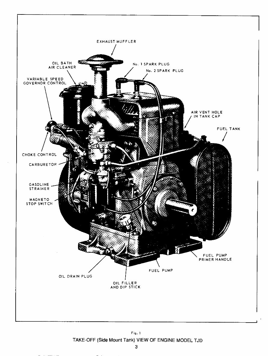
OIL BATH
AIR CLEANER
EXHAUST MUFFLER
/
No. 1 SPARK PLUG
No. 2 SPARK PLUG
AIR VENT HOLE
IN TANK CAP
FUEL TANK
/
CHOKE CONTROL
CARBURETOR
GASOLINE
STRAINER
MAGNETO
STOP SWITCH
OIL DRAIN PLUG
OIL FILLER
AND DIP STICK
FUEL PUMP
FUEL PUMP
PRIMER HANDLE
Fig. 1
TAKE-OFF (Side MountTank) VIEWOF ENGINE MODEL T,JD
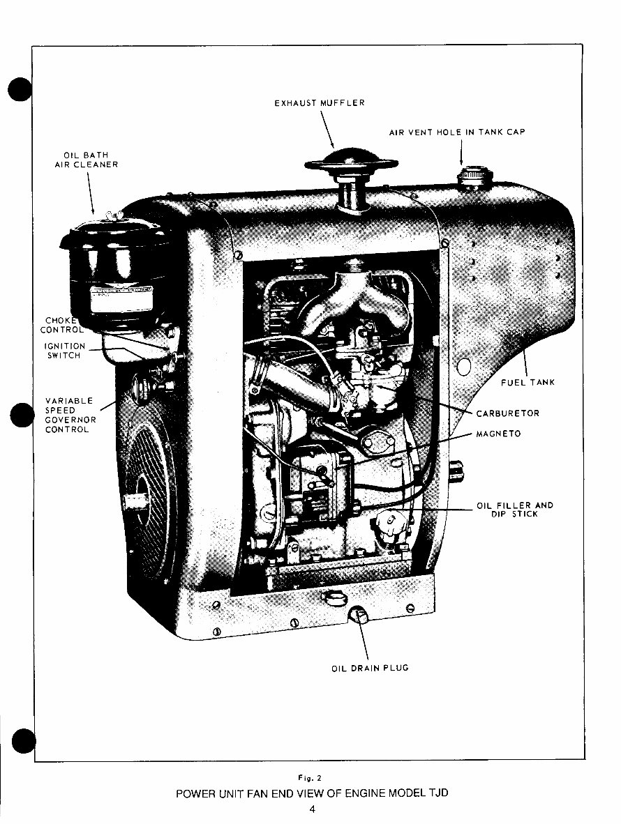
OIL BATH
AIR CLEANER
EXHAUST MUFFLER
AIR VENT HOLE
IN TANK CAP
1
CH
CONTRO
IGNITION
SWITCH
VARIABLE
SPEED
GOVERNOR
CONTROL
FUEL TANK
CARBURETOR
MAGNETO
OIL FILLER AND
DIP STICK
OIL DRAIN PLUG
Fig. 2
POWEI~ UNIT FAN END VIEW OF ENGINE MODEL TJD
4
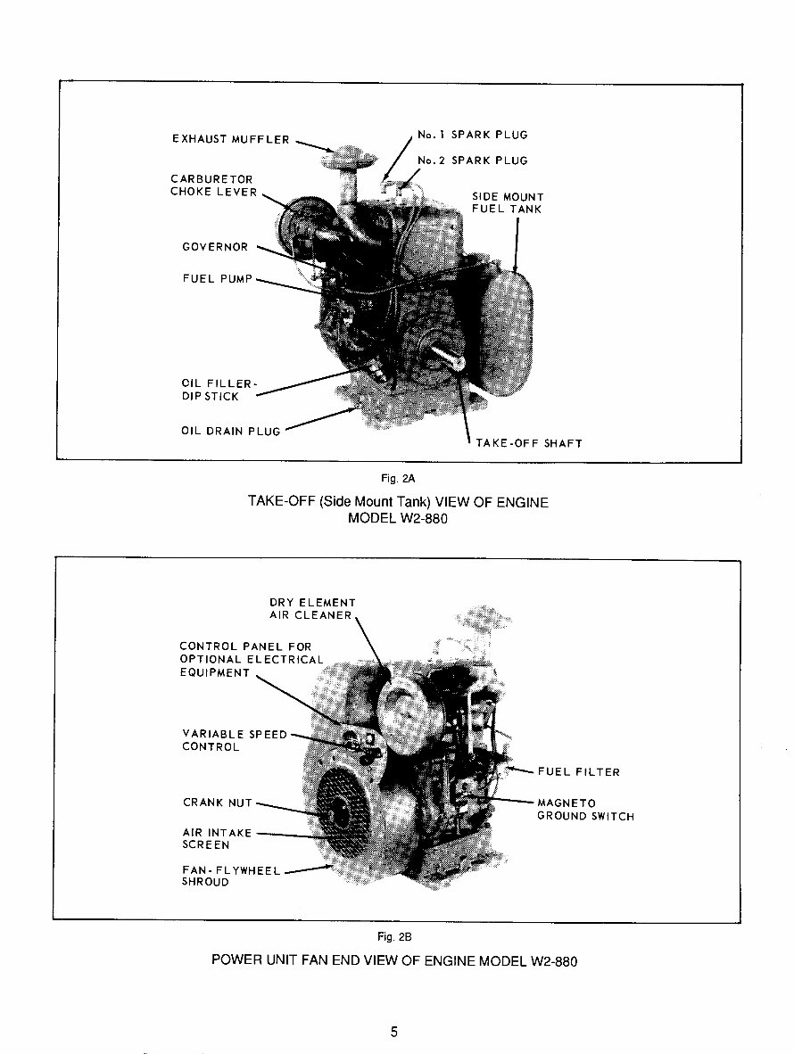
EXHAUST MUFFLER
CARBURETOR
CHOKE LEVER
No.l SPARK PLUG
No.2 SPARK PLUG
SIDE MOUNT
FUEL TANK
GOVERNOR
FUEL
OIL FILLERo
DIP STICK
OIL DRAIN PLUG
TAKE-OFF SHAFT
Fig. 2A
TAKE-OFF (Side MountTank) VIEW OF ENGINE
MODEL W2-880
DRY ELEMENT
AIR CLEANER
CONTROL PANEL FOR
OPTIONAL ELECTRICAL
EQUIPMENT
VARIABLE SPEED
CONTROL
CRANK NUT
AIRINTAKE
SCREEN
FAN-FLYWHEEL
SHROUD
FUEL FILTER
~NETO
GROUND SWITCH
Fig. 2B
POWER UNIT FAN ENDVIEW OF ENGINE MODEL W2-880
5
You're Reading a Preview
What's Included?
Fast Download Speeds
Online & Offline Access
Access PDF Contents & Bookmarks
Full Search Facility
Print one or all pages of your manual
$30.99
Viewed 48 Times Today


Secure transaction
What's Included?
Fast Download Speeds
Online & Offline Access
Access PDF Contents & Bookmarks
Full Search Facility
Print one or all pages of your manual
$30.99
The best manual available for these engines!
- File Format: .PDF
- Compatible: All Versions of Windows, Mac, and Linux
- Printable: Yes
- Downloadable: Instant High Speed
- Requirements: Adobe Reader


