D Service Bulletin Volvo Trucks North America Greensboro, NC USA Date Group No. Page 10.2008 255 56 1(11) Trucks This Service Bulletin replaces bulletins 255–56, 255–57 and 255–60, dated 3.2007. Actuator, Variable Geometry Turbocharger, Replacement D11F, D13B, D13F and D16F Engines Actuator, Variable Geometry Turbocharger, Replacement W2006206 This information covers the proper replacement procedure for the turbocharger Smart Remote Actuator (SRA) on the Volvo D11F, D13B, D13F and D16F engines. Contents • “Special Tools” page 2. • “Actuator, Variable Geometry Turbocharger, Replacement” page 3. Note: Information is subject to change without notice. Illustrations are used for reference only and can differ slightly from the actual engine version. However, key components addressed in this information are represented as accurately as possible. PV776-20168808 USA32115.ihval
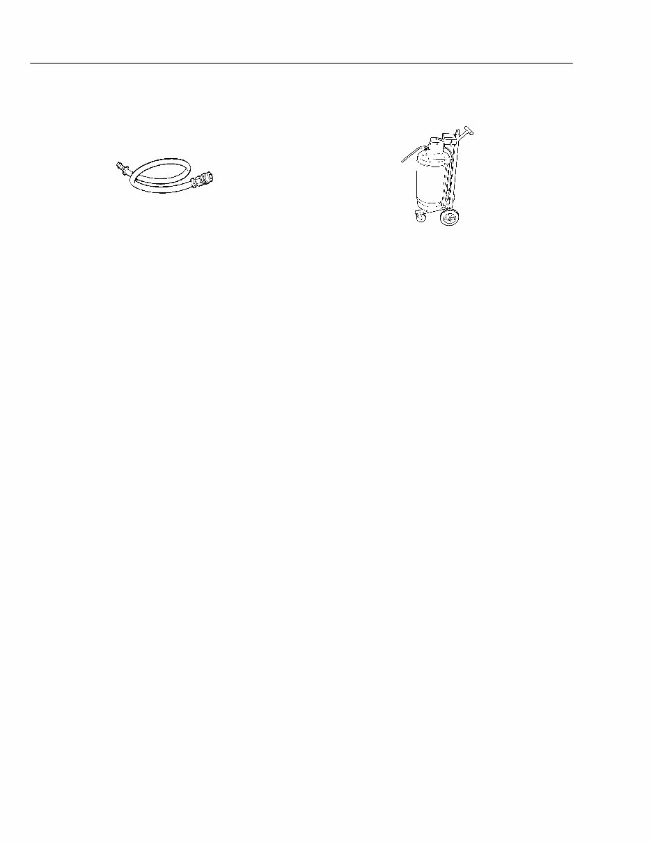
D Volvo Trucks North America Date Group No. Page Service Bulletin 10.2008 255 56 2(11) Special Tools For special tools ordering information, refer to Tool Information, group 08. W0001795 W2004191 9996049 Coolant Drain Hose DBT2V700 Coolant Extractor
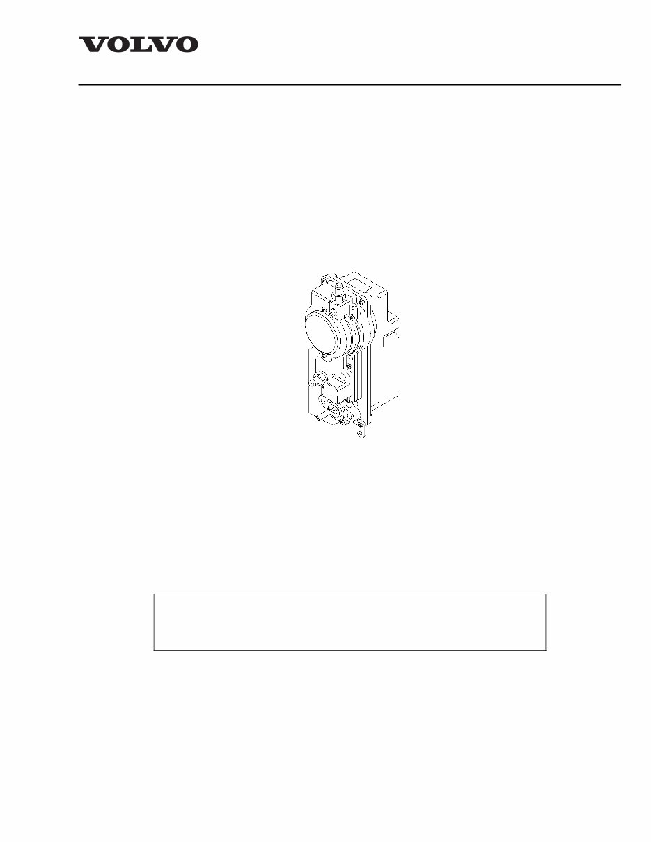
D Volvo Trucks North America Date Group No. Page Service Bulletin 10.2008 255 56 3(11) 2559-03-02-14 Actuator, Variable Geometry Turbocharger, Replacement You must read and understand the precautions and guidelines in Service Information, group 20, "General Safety Practices, Engine" before performing this procedure. If you are not properly trained and certified in this procedure, ask your supervisor for training before you perform it. Special tools: 9996049, DBT2V700 Removal 1 Apply the parking brake and place the shift lever in neutral. 2 W2003815 Remove all cables from ground (negative) battery terminals to prevent personal injury from electrical shock. 3 Using pressure wash equipment, clean the turbocharger actuator while it is still mounted. Note: Make sure all electrical connections and coolant pipes in the area of the turbocharger actuator are securely fastened.
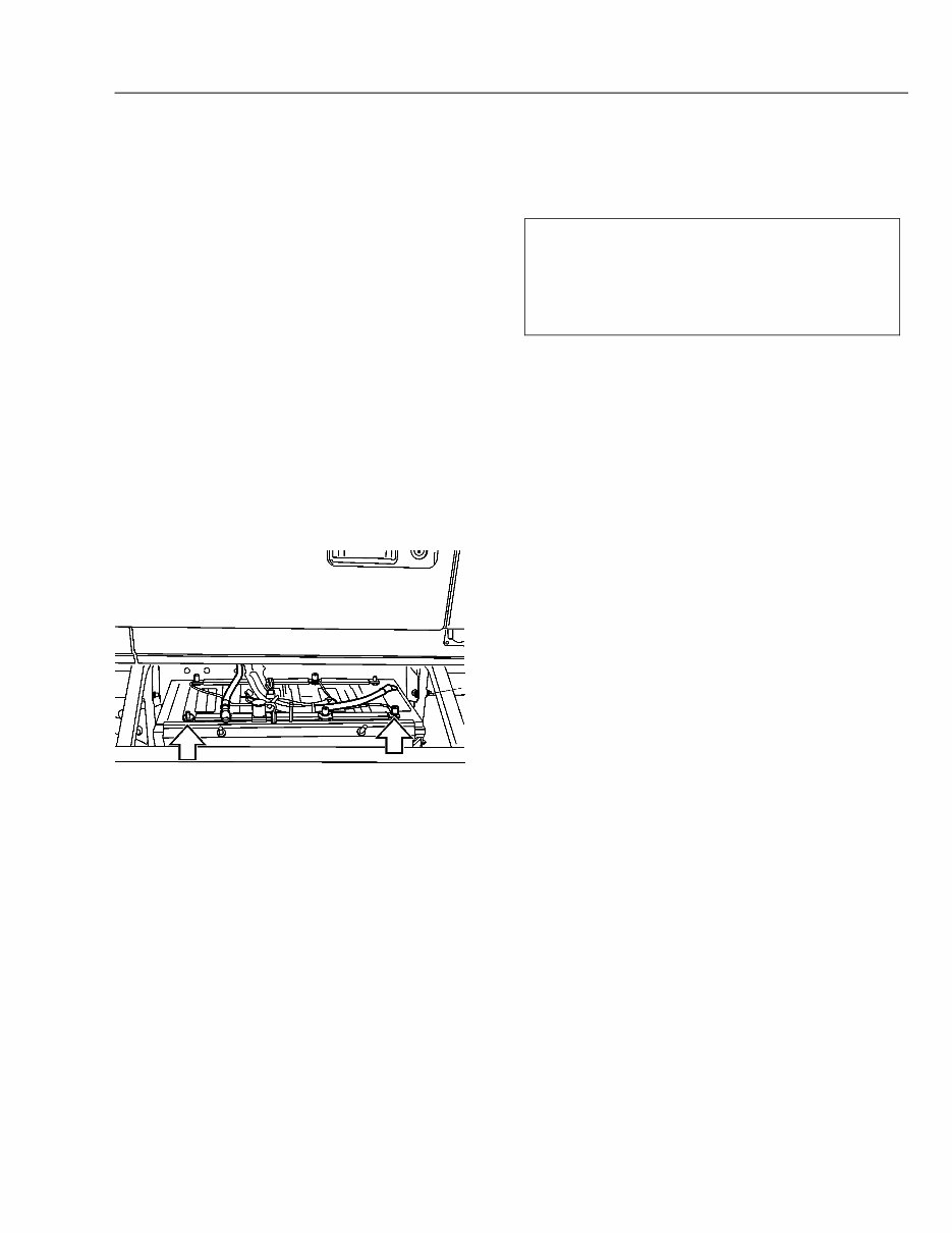
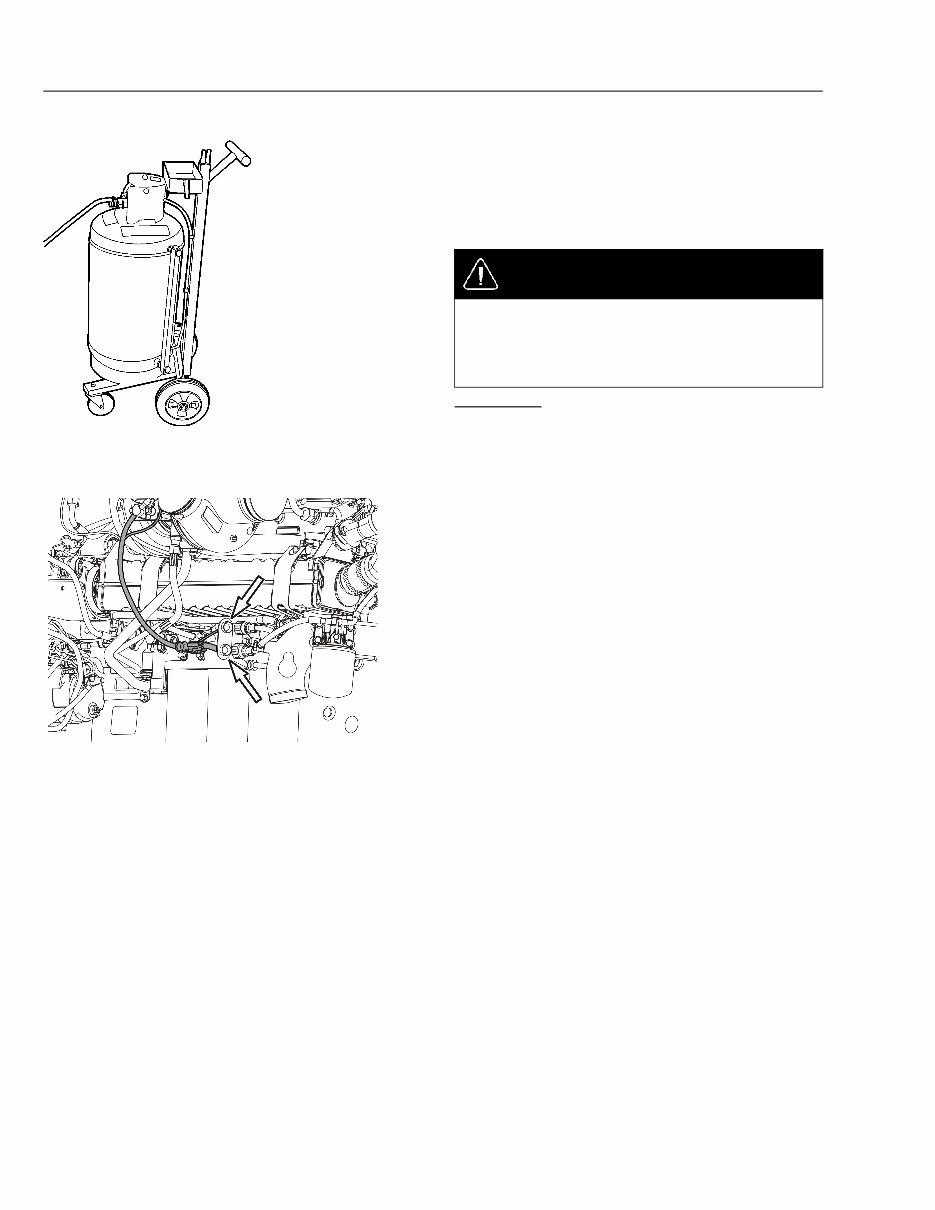
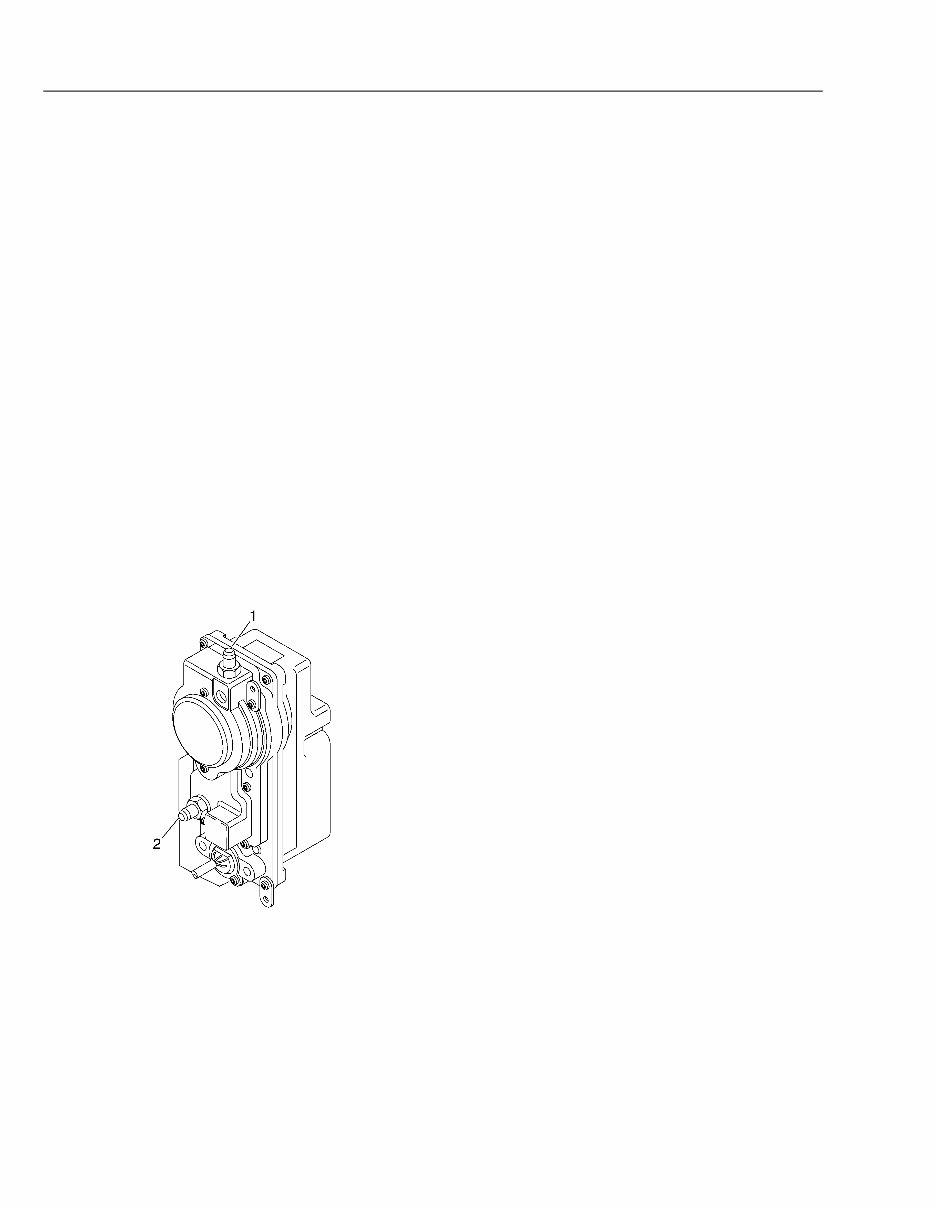
D Volvo Trucks North America Date Group No. Page Service Bulletin 10.2008 255 56 4(11) 4 W2004191 Connect the coolant extractor to the drain fitting at the bottom of the radiator and drain the coolant. Note: If the coolant extractor is unavailable, connect the coolant drain hose to the drain fitting and drain the coolant into an appropriate container. DANGER Coolant is toxic; risk of poisoning. Do not drink coolant. Use proper hand protection when handling. Keep coolant out of reach of children and animals. Failure to follow these precautions can cause serious illness or death. DBT2V700, 9996049 5 W2005620 Disconnect the actuator assembly electrical connector at the wiring harness. Cut any tie straps as needed.
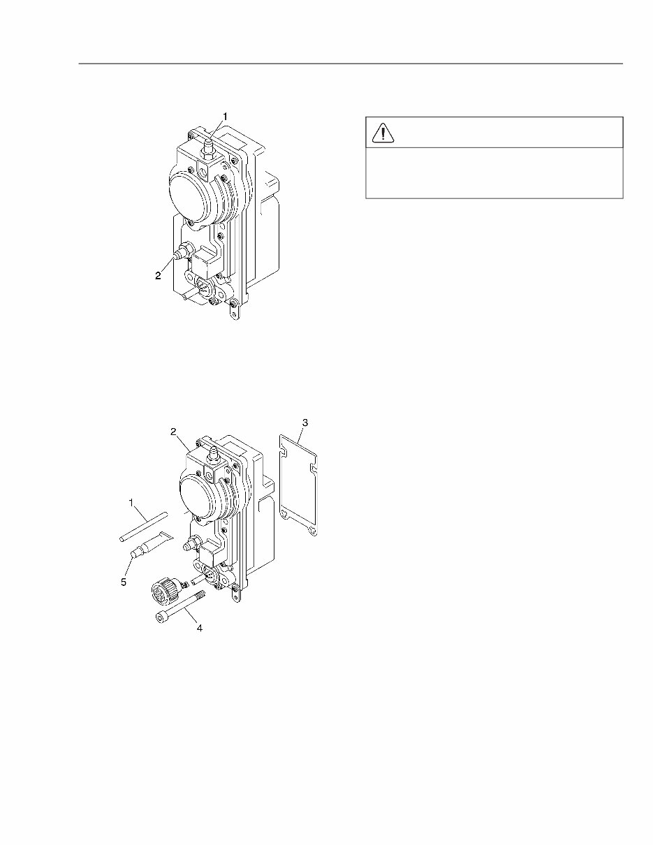
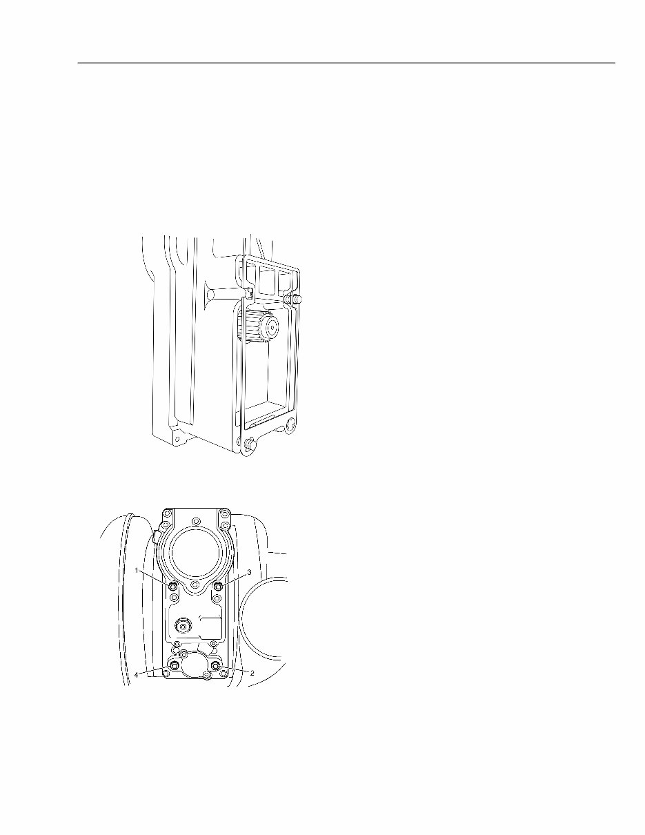
D Volvo Trucks North America Date Group No. Page Service Bulletin 10.2008 255 56 5(11) 6 W2005699 1 Coolant Return Port 2 Coolant Inlet Port Disconnect the coolant lines from the actuator. CAUTION Protect the insides of the actuator assembly and the exposed parts from contamination when removed. Failure to do so can result in component malfunction or failure. 7 W2005698 1 Alignment Pin 2 Actuator Housing 3 Gasket 4 Screw (4 Required) 5 Grease Applicator Tube Remove the actuator from the turbocharger. Remove and discard the gasket.
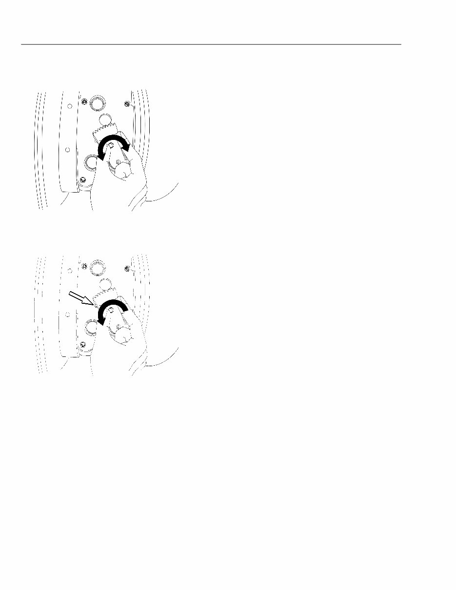
D Volvo Trucks North America Date Group No. Page Service Bulletin 10.2008 255 56 6(11) Installation 1 W2005277 Using gloves, manually rotate the turbocharger sector gear back and forth (counterclockwise and clockwise). It should be noted that when the sector gear is at the end of travel, or at an end stop, it can require significant force to overcome friction then, start it’s motion in the opposite direction. This is normal and not cause for concern. Apply more force to move the sector gear. Once in motion, the sector gear movement should be smooth, without binding or sticking until it reaches it’s end of travel (end stop). 2 W2006758 Alignment Hole Inspection, 3mm (0.118 inch) Hole Rotate the sector gear fully counterclockwise until contact is made with the end stop of the variable geometry internal mechanism. 1/4 to 3/4 of the 3mm (0.118 inch) reference hole should be visible at the edge of the sector gear nearest the turbine housing.
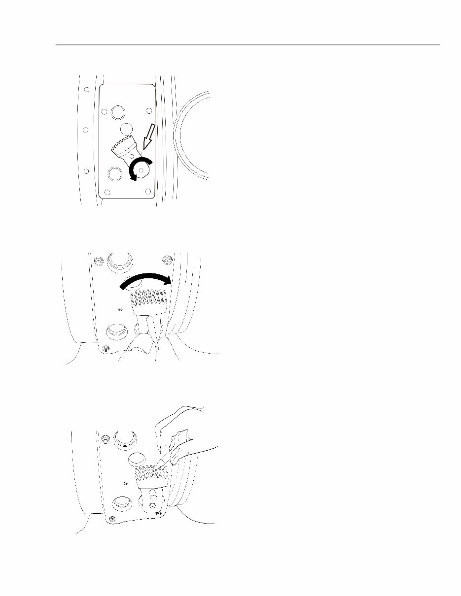
D Volvo Trucks North America Date Group No. Page Service Bulletin 10.2008 255 56 7(11) 3 W2005276 For turbochargers manufactured without the small 3mm (0.118 inch) alignment hole, a portion (half) of the 5mm (0.197 inch) alignment hole should be exposed at the compressor housing side of the sector gear when the sector gear is fully rotated toward the turbine housing. 4 W2005275 Rotate the sector gear fully clockwise. Make sure that the alignment pin fits through the sector gear into the alignment hole in the housing. The diameter of the alignment hole is 5mm (0.197 inch). Note: If the sector gear does not align properly with the alignment hole or does not rotate properly in either direction, replace the turbocharger. 5 W2006760 Lubricate the sector gear teeth using the grease applicator tube that comes in the installation kit.
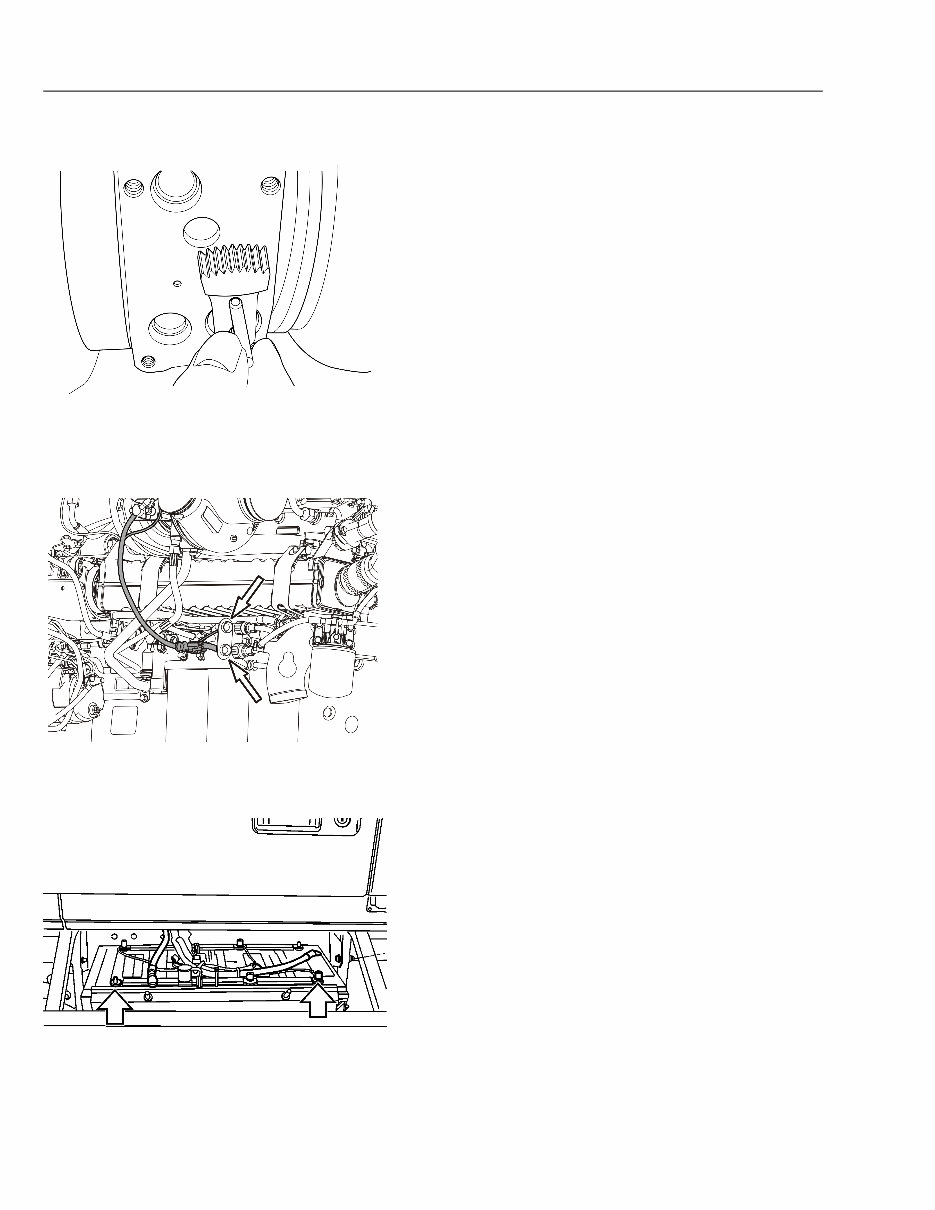
D Volvo Trucks North America Date Group No. Page Service Bulletin 10.2008 255 56 8(11) 6 W2005209 Remove the alignment pin without disturbing the position of the sector gear. The gear must not be moved from this position. 7 W2005620 Connect the actuator electrical wiring harness connector to the engine wiring harness connector. Install tie straps as needed to secure the harness. 8 W2003815 Install all previously removed cables to the ground (negative) battery terminals.
D Volvo Trucks North America Date Group No. Page Service Bulletin 10.2008 255 56 9(11) 9 Connect the VCADS Pro PC to the vehicle diagnostic data connector and turn the ignition switch ON. Using the directions in VCADS Pro, command the actuator to the install position. Turn OFF the ignition switch when done. Note: Do not disturb the actuator drive gear after the gear is in the install position. Proper calibration of the actuator drive gear to the turbocharger sector gear must be maintained for proper operation. 10 W2005211 Install two new mounting screws diagonally across the actuator. Place a new gasket over the protruding screws at the back of the actuator. Note: Always use the new screws and gasket provided in the actuator installation kit. 11 W2005242 Carefully align the actuator with the turbocharger and install it into position. Hold the actuator in place and hand tighten the two screws. Install the two remaining new screws and hand tighten. Use the following steps to tighten the screws. 1 Tighten the screws in the pattern shown to 3 Nm (27 in-lb). 2 Tighten the screws in the pattern shown to 11 Nm (97 in-lb).
D Volvo Trucks North America Date Group No. Page Service Bulletin 10.2008 255 56 10(11) 12 Connect the VCADS Pro PC to the diagnostic data connector and turn ON the ignition switch. Using the on screen directions in VCADS Pro, perform the VGT calibration procedure. If the actuator is installed correctly, the procedure indicates a successful VGT calibration. If the calibration fails, either the pre-positioning of the actuator drive gear is incorrect, the sector gear positioning is incorrect, the actuator is faulty or the turbocharger sector gear and nozzle ring mechanism is damaged. Turn OFF the ignition switch when done. 13 If the actuator is suspected of being faulty and requires replacement, follow the preceding installation steps with the new actuator. Note: There are two actuator installation kits available: • A kit that includes the gasket, screws, alignment pin and gear lubrication grease for an existing actuator installation. • A kit that includes the actuator, gasket, screws, alignment pin and gear lubrication grease for a new actuator installation. 14 W2005699 1 Coolant Return Port 2 Coolant Inlet Port Connect the coolant lines to the actuator and tighten the fittings.
This professional technical manual contains service, maintenance, troubleshooting, and replacement procedures for your engine, including step-by-step instructions, clear images, and exploded-view illustrations.
Indeed, the manufacturer-sourced and easy-to-understand procedures, once combined with illustrations, make it possible for anyone to safely and efficiently service and repair their engine.
This engine service & repair manual contains every troubleshooting and replacement procedure provided by the manufacturer, including step-by-step instructions, exploded-view illustrations, torque specs, and clear images — everything you need to diagnose, repair, or overhaul your engine in no time!
No need to flip through hundreds of pages to find specific information; no more greasy, torn, or lost pages anymore! Carry them around, search them, screenshot them, bookmark them — much better than a traditional bound manual if you ask me.
Of course, if you prefer to have a physical copy, nothing prevents you from printing it out too.
Table of Contents:
Lubrication and Oil System Design and Function
Main Bearings Replace
Nox Sensor and Control Module Replacement Compact
Nox Sensor and Control Module Replacement Vertical
Exhaust After Treatment System Design and Function
Exhaust Aftertreatment System Fault Tracing
Fan Literature
Filter Water Separator Replacement
Flywheel Bearing Replacement
Flywheel Ring Gear Replacement
Flywheel Sensor Depth Check
Flywheel Sensor Distance Check
Fuel Overflow Valve Replacement
Fuel System Design and Function
Fuel System Specifications
Fuel System Troubleshooting
Hose Clamps Charge Air Cooler Replacement
Injector Aftertreatment Clean
Intake and Exhaust System Design and Function
Intake Manifold Gasket Replacement
Format: .pdf Printable: Yes Language: English Compatibility: Pretty much any electronic device, incl. PC & Mac computers, Android and Apple smartphones & tablet, etc. Requirements: Adobe Reader (free)