VM Motori R750 Series R754, R756 Diesel Engine Complete Workshop Service Repair Manual
What's Included?
Lifetime Access
Fast Download Speeds
Online & Offline Access
Access PDF Contents & Bookmarks
Full Search Facility
Print one or all pages of your manual
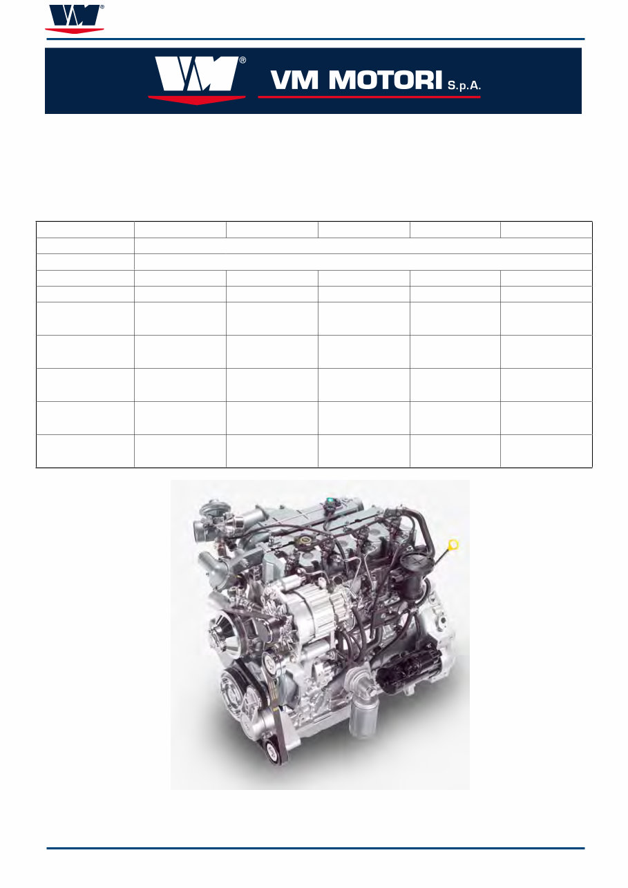
R 750 VM Order Number 42431133F Edition 7 - 03/2010 Workshop Manual Engine Family R750 R754EU4 R756EU4 R756IE3 R754EU5 R756EU5 R Common Rail Injection System 750 Unitary Displacement 4 (no. of cylinders) 4 x x 4 x 6 (no. of cylinders) x 6 6 x 6 Turbocharged yes yes yes yes yes I (Intercooler) yes yes yes yes yes EU4 - Emissions Certification EURO 4 EC/EPA Stage3A EURO 4 EC/EPA Stage3A x x x E3 - Emissions Certification x x EC/EPA Stage3A x x EU5 - Emissions Certification x x x EURO 5 EC/EPA Stage3B EURO 5 EC/EPA Stage3B
R 750 SECTIONS INTRODUCTION ...................................................................................................................... 6 HANDLING PRECAUTIONS FOR ELECTRIC CIRCUITS ...................................................... 8 SERVICE MANUAL - UPDATING .......................................................................................... 13 GENERAL INFORMATION ..................................................................................................... 16 MAINTENANCE ...................................................................................................................... 18 REMOVAL AND INSTALLATION ........................................................................................... 50 FASTENER TIGHTENING SPECIFICATIONS ....................................................................... 51 SPECIAL TOOLS.................................................................................................................... 52 TIMING SIDE........................................................................................................................... 56 EXHAUST SIDE ...................................................................................................................... 83 FLYWHEEL SIDE.................................................................................................................... 91 BASIC ENGINE...................................................................................................................... 100 ENGINE BLOCK .................................................................................................................... 134 ENGINE BLOCK .................................................................................................................... 135 INJECTION SIDE ................................................................................................................... 151 ENGINE ELECTRICAL .......................................................................................................... 169 ENGINE CONTROL ............................................................................................................... 173 LABOUR TIME GUIDE .......................................................................................................... 190 ELECTRICAL SYSTEM ......................................................................................................... 197
R 750 3 SUMMARY INTRODUCTION ...................................................................................................................... 6 MODELS COVERED ....................................................................................................................................... 6 R 754 AND 756 EU4/EU5 COMMON RAIL INDUSTRIAL ENGINES ARE APPLIED TO VEHICLES OF THE ROAD, SUCH AS ROAD SWEEPERS AND TRUCKS. R 756 IE3 ARE APPLIED TO VEHICLES NOT OF THE ROAD, AGRICULTURAL AND LIFTING APPLICATION. ................................................................................. 6 NOTICE TO USERS OF THIS MANUAL ......................................................................................................... 6 REPLACEMENT PARTS .................................................................................................................................. 7 CLEANLINESS AND CARE OF PRODUCT .................................................................................................... 7 HANDLING PRECAUTIONS FOR ELECTRIC CIRCUITS ...................................................... 8 ENGINE ELECTRONIC CONTROL UNIT ....................................................................................................... 8 PRECAUTIONS FOR ARC WELDING............................................................................................................. 12 SERVICE MANUAL - UPDATING .......................................................................................... 13 GENERAL INFORMATION ..................................................................................................... 16 INTRODUCTION .............................................................................................................................................. 16 HOW TO ORDER THIS MANUAL.................................................................................................................... 16 ENGINE SERIAL NUMBER AND ENGINE PLATE IDENTIFICATION............................................................. 16 MAINTENANCE ...................................................................................................................... 18 ENGINE SPECIFICATIONS ............................................................................................................................. 18 MAINTENANCE INTERVALS .......................................................................................................................... 24 MAINTENANCE SCHEDULE - R750 EURO 4 - IE3 ....................................................................................... 24 MAINTENANCE SCHEDULE - R750 EURO 5 ................................................................................................ 25 ENGINE EXTERNAL VIEWS ........................................................................................................................... 26 ENGINE OIL .................................................................................................................................................... 30 COOLANT ........................................................................................................................................................ 35 AIR FILTER ELEMENT .................................................................................................................................... 38 FUEL SYSTEM ................................................................................................................................................ 41 FUEL FILTER ................................................................................................................................................... 42 ALTERNATOR BELT / POLY - V (SERPENTINE) ........................................................................................... 44 DIESEL PARTICULATE FILTER (DPF) - R 750 EURO 4................................................................................. 46 DIESEL PARTICULATE FILTER (DPF) - R 750 EURO 5................................................................................. 48 EXTENDED STORAGE ................................................................................................................................... 49 REMOVAL AND INSTALLATION ........................................................................................... 50 FASTENER TIGHTENING SPECIFICATIONS ....................................................................... 51 SPECIAL TOOLS.................................................................................................................... 52 TIMING SIDE........................................................................................................................... 56 TIMING GEARS ............................................................................................................................................... 57 OIL PUMP ........................................................................................................................................................ 60 CRANKSHAFT GEAR ...................................................................................................................................... 65 HYDRAULIC PUMP IDLER GEAR (BETWEEN THE CRANKSHAFT AND CAMSHAFT GEARS) ................. 66 INJECTION PUMP IDLER GEAR (BETWEEN THE CAMSHAFT AND INJECTION PUMP GEARS) ............. 69 HYDRAULIC PUMP GEAR ASSEMBLY .......................................................................................................... 70 BELT TENSIONER - (AUTOMATIC TYPE) ...................................................................................................... 74 BELT TENSIONER BRACKET ......................................................................................................................... 75 IDLER PULLEYS.............................................................................................................................................. 76 CRANKSHAFT HUB AND PULLEY ................................................................................................................. 77 WATER PUMP AND PULLEY .......................................................................................................................... 80 TIMING GEAR COVER .................................................................................................................................... 81 FRONT OIL SEAL ............................................................................................................................................ 82 EXHAUST SIDE ...................................................................................................................... 83 TURBOCHARGER ........................................................................................................................................... 83 EGR COOLER ................................................................................................................................................. 84 INTAKE THROTTLE / EGR VALVE & PROPER ACTUATORS ...................................................................... 86 EXHAUST MANIFOLD ..................................................................................................................................... 89 INTAKE MANIFOLD ......................................................................................................................................... 90
R 750 4 FLYWHEEL SIDE.................................................................................................................... 91 CRANKSHAFT END PLAY (AXIAL CLEARANCE) .......................................................................................... 91 FLYWHEEL ...................................................................................................................................................... 92 FLYWHEEL RING GEAR ................................................................................................................................. 95 FLYWHELL HOUSING ..................................................................................................................................... 96 REAR MAIN BEARING CARRIER ................................................................................................................... 98 THRUST WASHERS ........................................................................................................................................ 98 REAR MAIN BEARING ................................................................................................................................... 99 REAR OIL SEAL............................................................................................................................................... 99 CPS TARGET WHEEL BOLT ........................................................................................................................... 99 BASIC ENGINE...................................................................................................................... 100 CYLINDER HEAD GASKET............................................................................................................................. 100 CYLINDER HEAD ............................................................................................................................................ 101 TORQUE PROCEDURE AFTER THE FIRST 20-30 MINUTES OF OPERATION........................................... 104 EXPANSION PLUGS ....................................................................................................................................... 105 CYLINDER HEAD END SPACER .................................................................................................................... 105 VALVE GUIDES ............................................................................................................................................... 106 VALVE SEATS .................................................................................................................................................. 108 VALVE SEAT RECONDITIONING ................................................................................................................... 109 VALVES ............................................................................................................................................................ 110 VALVE SPRINGS ............................................................................................................................................. 112 ROCKER ARM ................................................................................................................................................. 113 VALVE LIFTERS .............................................................................................................................................. 115 VALVE PUSH RODS ........................................................................................................................................ 117 FRACTURED CONNECTING ROD ................................................................................................................. 118 REMOVAL ........................................................................................................................................................ 118 BROACHED CONNECTING ROD ................................................................................................................... 122 REMOVAL ........................................................................................................................................................ 122 PISTON ............................................................................................................................................................ 126 OIL PAN & OIL PICKUP ................................................................................................................................... 131 OIL PICKUP ..................................................................................................................................................... 131 OIL PRESSURE RELIEF VALVE ..................................................................................................................... 132 ENGINE BLOCK .................................................................................................................... 134 CRANKCASE ................................................................................................................................................... 134 ENGINE BLOCK .................................................................................................................... 135 LINER ............................................................................................................................................................... 135 CAMSHAFT...................................................................................................................................................... 138 CAMSHAFT BEARINGS ................................................................................................................................. 141 FRONT JOURNAL CAMSHAFT BUSHING ..................................................................................................... 142 PISTON COOLING JETS (OIL SPRAY NOZZLES) ......................................................................................... 143 CRANKSHAFT ................................................................................................................................................. 144 CRANKSHAFT FRONT MAIN BEARING ........................................................................................................ 150 INJECTION SIDE ................................................................................................................... 151 INJECTION FUEL SYSTEM............................................................................................................................. 151 ELECTRICAL SENSORS ................................................................................................................................ 152 LOW PRESSURE SYSTEM REQUIREMENTS............................................................................................... 156 HIGH PRESSURE PUMP ................................................................................................................................ 157 INJECTOR........................................................................................................................................................ 160 RAIL ................................................................................................................................................................. 162 HIGH PRESSURE FUEL COMPONENTS TIGHTENING PROCEDURE........................................................ 163 OIL FILTER HOUSING ..................................................................................................................................... 164 OIL DELIVERY PIPE TO ROCKER ARM ......................................................................................................... 165 ROCKER ARM COVER ................................................................................................................................... 166 COOLANT MANIFOLD .................................................................................................................................... 166 THERMOSTATIC VALVE ................................................................................................................................ 167 VACUUM PUMP............................................................................................................................................... 168
R 750 5 Introduction ENGINE ELECTRICAL .......................................................................................................... 169 ALTERNATOR .................................................................................................................................................. 169 ALTERNATOR PULLEY ................................................................................................................................... 169 VOLTAGE REGULATOR .................................................................................................................................. 172 ALTERNATOR BRACKET ................................................................................................................................ 172 STARTER ......................................................................................................................................................... 172 ENGINE CONTROL ............................................................................................................... 173 DIAGNOSTIC TROUBLE CODES “EURO 4” .................................................................................................. 173 DIAGNOSTIC TROUBLE CODES “EURO 5” .................................................................................................. 179 LABOUR TIME GUIDE .......................................................................................................... 190 KEY TO DEFINITIONS..................................................................................................................................... 190 ELECTRICAL SYSTEM ......................................................................................................... 197 ELECTRICAL SCHEMATIC DIAGRAMS ........................................................................................................ 197 ENGINE WIRING HARNESS ........................................................................................................................... 199 INSTALLATION ELECTRIC DIAGRAM ............................................................................................................ 203
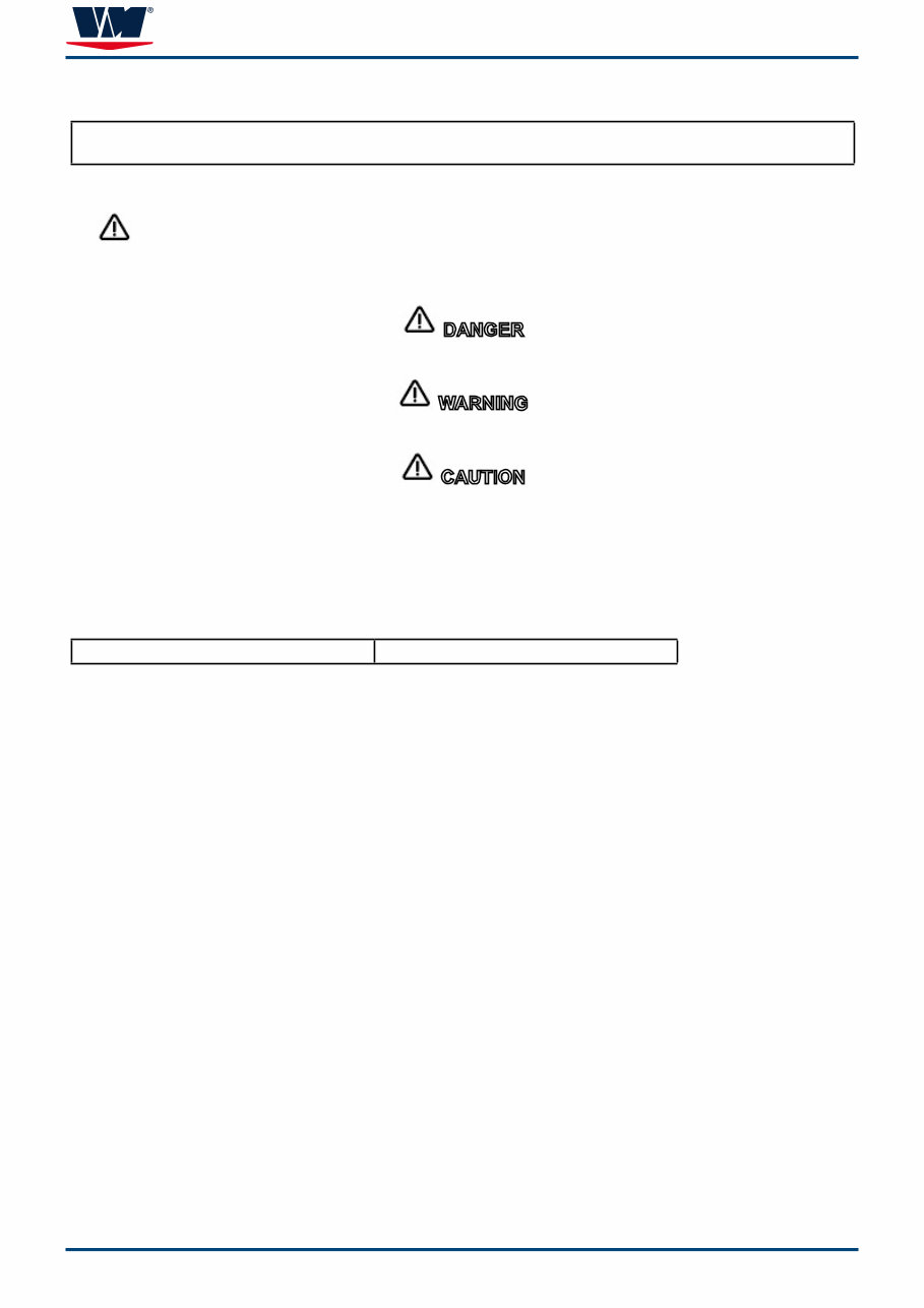
R 750 7 Introduction REPLACEMENT PARTS Use of parts other than the recommended service re- placement parts, will avoid the warranty on those parts that are damaged as a result. WARNING When servicing the electrical, ignition and fuel sy- stems, it is extremely important that all components are properly installed and tightened. If not, any electrical or ignition component opening would permit sparks to ignite fuel vapors from fuel system leaks, if they existed. CLEANLINESS AND CARE OF PRO- DUCT A VM Motori Product is a combination of many machi- ned, honed, polished and lapped surfaces with tole- rances that are measured in the thousands of a mm. When any product component is serviced, care and cleanliness are important. Throughout this manual, it should be understood that proper cleaning and protection of machined surfaces and friction areas is a part of the repair procedure. This is considered standard shop practice even if not specifically stated. Whenever components are removed for service, they should be retained in order. At the time of installation, they should be installed in the same locations and with the same mating surfaces as when removed. Any time the intake or exhaust openings are expo- sed during service they should be covered to protect against accidental entrance of foreign material which could enter the cylinders and cause extensive internal damage when the engine is started. It is important to note, during any maintenance proce- dure replacement fasteners must have the same mea- surements and strength as those removed. Numbers on the heads of the metric bolts and on the surfaces of metric nuts indicate their strength. American bolts use radial lines for this purpose, while most American nuts do not have strength markings. Mismatched or incorrect fasteners can result in dama- ge or malfunction, or possibly personal injury. There- fore, fasteners removed should be saved for reuse in the same locations whenever possible. Where the fasteners are not satisfactory for reuse, care should be taken to select a replacement that matches the origi- nal. Personnel should not work on or under an engine that is suspended. Engines should be attached to work stands, or lowered to ground as soon as possible.
R 750 Introduction HANDLING PRECAUTIONS FOR ELECTRIC CIRCUITS ENGINE ELECTRONIC CONTROL UNIT WARNING IN ORDER TO AVOID ECU DAMAGE PAY ATTENTION TO THE FOLLOWING INSTRUCTIONS: DO NOT CUT ENGINE VOLTAGE OFF DURING ENGINE OPERATION BEFORE CUT ENGINE VOLTAGE OFF THROUGH ELET- TRICAL DEVICES (BREAKERS, SWITCH, ETC.) WAIT FOR 30 SEC. AT LEAST SO THAT THE ECU CAN BE CARRIED OUT THE “AFTER-RUN” PROCEDURE DO NOT USE START BOOSTER TO LET START THE EN- GINE • • •
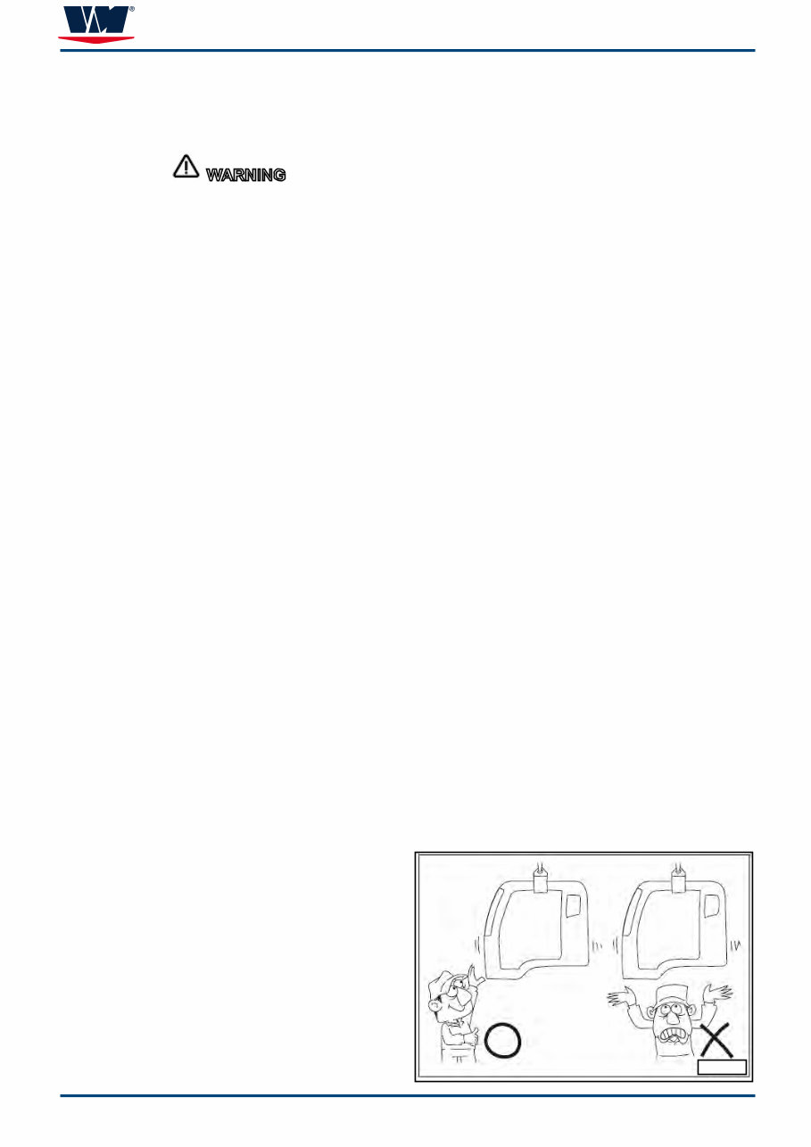
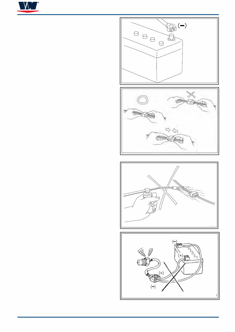
R 750 9 Introduction It should be kept in mind, while working on the product, that the electrical systems are capable of violent and damaging short circuits or severe electrical shocks. When performing any work where electrical terminals could possibly be grounded or touched by the mecha- nic, the battery cables should be disconnected at the battery. Before working on the electrical system, disconnect the (–) battery cable to prevent short circuits. CAUTION Make sure the starter switch and lighting switches are OFF before disconnecting or connecting battery cable. Semiconductor components may otherwise be dama- ged. When separating connectors, grasp the connectors themselves rather than the harnesses.To separate locking connectors, first push them in the direction of the arrows. To reconnect locking connectors, push them together until they click. Before washing the engine, cover electrical parts to keep them dry. (Use plastic sheets or the like.) Keep water away from harness connectors and sensors and immediately wipe off any water that gets on them. When applying a voltage to a part for inspection pur- poses, check that the (+) and (–) cables are connected properly then gradually increase the voltage from zero. Do not exceed the specified voltage. Remember that control units and sensors do not ne- cessarily operate on the battery voltage. CAUTION
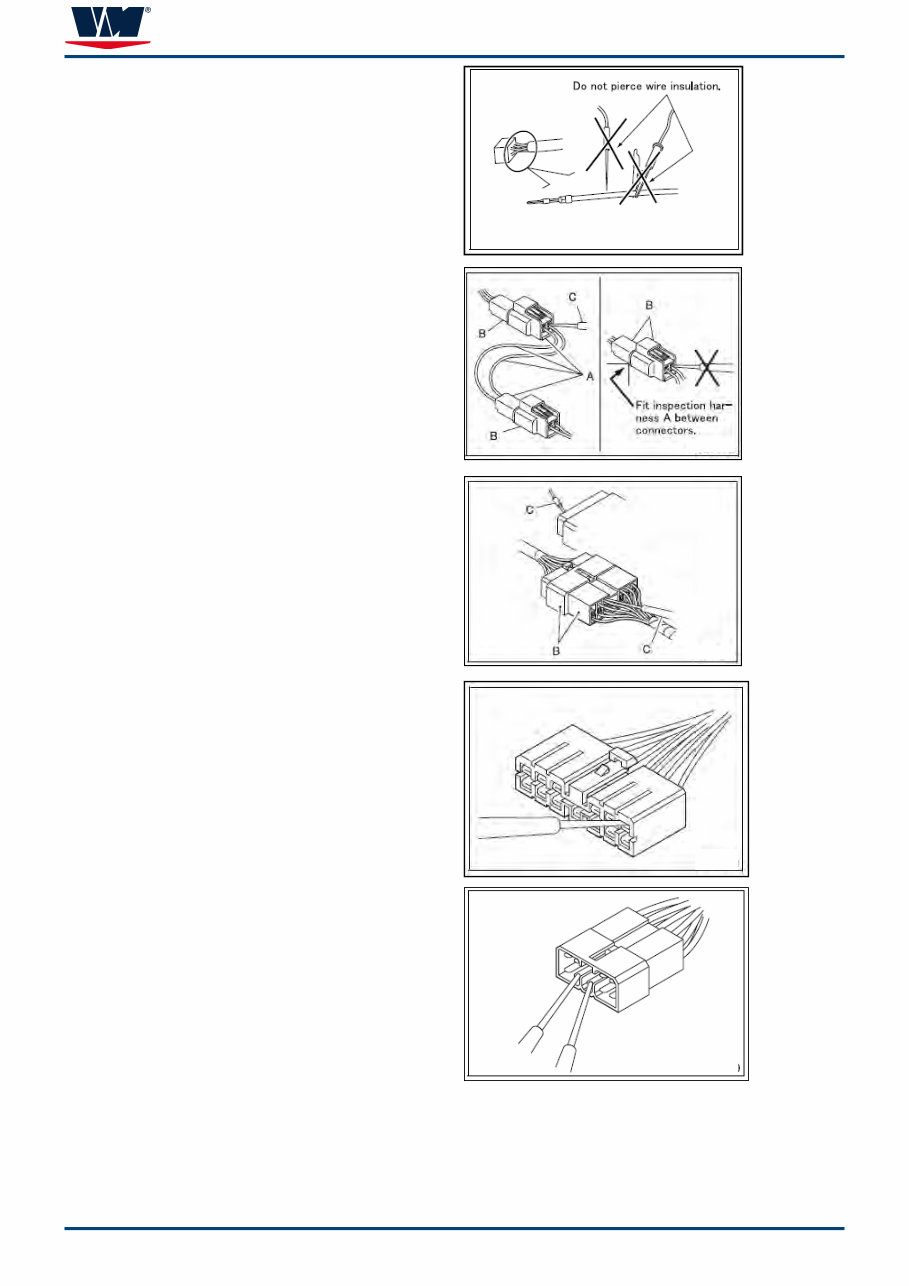
R 750 0 Introduction • Do not pierce wire insulation with test probes or alligator clips when performing electrical inspections. Doing so can, particularly with the chassis harness, hasten corrosion. INSPECTION OF HARNESSES INSPECTIONS WITH CONNECTORS FITTED TO- GETHER Waterproof connectors • Connect an inspection harness and connector A between the connectors B of the circuit to be ins- pected. Perform the inspection by applying a test probe C to the connectors of the inspection harness. Do not insert the test probe C into the wire-entry sides of the waterproof connectors since this would damage their waterproof seals and lead to rust. Non-waterproof connectors Perform the inspection by inserting a test probe C into the wireentry sides of the connectors. An extra-narrow probe is required for control unit connectors, which are smaller than other types of connector. Do not force a regular-size probe into control unit connectors since this would cause damage. INSPECTIONS WITH CONNECTORS SEPARATED Inspections on female terminals Perform the inspection by carefully inserting a test pro- be into the terminals. Do not force the test probe into the terminals since this could deform them and cause poor connections. Inspections on male terminals Perform the inspection by applying test probes directly to the pins. CAUTION . • Be careful not to short-circuit pins together with the test probes. With control unit connectors, short-cir- cuiting of pins can cause damage to the control unit’s internal circuitry. When using a multimeter to check continuity, do not
Thank you for considering this comprehensive Workshop Service Repair Manual for the VM Motori R750 Series R754 and R756 Diesel Engines.
This manual is an invaluable resource for both professional mechanics and DIY enthusiasts, covering every service and repair procedure with easy-to-follow step-by-step instructions and detailed illustrations.
By utilizing this manual, you can significantly reduce repair costs by performing maintenance and repairs on your own. The manual is yours to keep forever, allowing you to print specific pages, chapters, or the entire manual. Additionally, you can conveniently access it on your tablet or smartphone.
All models, engines, trim, and transmission types are included in this manual, ensuring comprehensive coverage for all your repair needs.
Key features of this high-quality Service Repair Workshop Manual include complete A-Z repair procedures, with every service and repair task thoroughly documented.
Compatibility is not an issue, as this manual is designed to work seamlessly on all PC and MAC computers, tablets, and mobile phones. The only software requirement is Adobe Reader, which is commonly pre-installed on most computers or can be downloaded for free.
Upon payment confirmation through Visa, MasterCard, or PayPal, the manual will be instantly emailed to the address provided during checkout, ensuring prompt access to the valuable resource.
Rest assured, customer satisfaction is guaranteed with this Workshop Service Repair Manual.
Recently Viewed
5,521,897Happy Clients
2,594,462eManuals
1,120,453Trusted Sellers
15Years in Business
Price:
Actual Price:
VM Motori R750 Series R754, R756 Diesel Engine Complete Workshop Service Repair Manual