KNI4012 WIM 9F_ 11_ AI__ AIL_ AZA iff A410 3=STK C 1E I2c FNGINFFRING CO_ I TE
Foreword . . . Q UALITY and the ability to give long and reliable service are the primary con- siderations in the production of all Villiers engines, but when servicing eventually becomes necessary it is very important that the correct tolerances are maintained and it is, therefore, essential that only genuine Villiers spares are used. The power units covered by this manual are the 148 c.c., 173 c.c., 197 c.c. and 246 c.c. engine-gear units adopted as standard equipment by the leading manufacturers of motor cycles, motor scooters, etc. The models tre the Marks 31C, 2L, 3L, 9E and 32A, 34A respectively, the basic specifications being for motor cycle power units. All models are available with either three or four-speed gearbox, and for kcooter applications where the power unit is more-or-less enclosed, a fan with cowling is provided. Normally, starting the engine is by kickstarter, but all models are available having the SIBA " Dynastart " unit giving either uni-directional rotation only, or reversing rotation in addition. Routine maintenance and lubrication are fully dealt with in the Rider's Handbook and is not repeated in these pages, but it is recommended that the reader obtains copies of both the User's Handbook V.E.C.542 and Illustrated Spare Parts List V.E.C.545 with complete " exploded " drawings which used in conjunction with this Manual will, we believe, prove invaluable. It is also suggested that the following literature is obtained from Villiers Service Department :— Service Bulletins M/C34, 35, 37, 39, 43, 46, 47, 48, 49, 50. Service Instructions SIBA " Dynastart " V.E.C.549 Sheets 1-9. Ignition Test Unit Model M.3089 V.E.C.27. Every engine is built to a works specification, the number of which is stamped on the nameplate attached, usually to the inner chaincase. This number, together with the serial number, should be quoted in any correspondence in connection with repairs or replacement parts. Our Service Department will gladly deal with any problems in connection with Villiers products.
WORKSHOP MANUAL Marks 9E, 2L, 3L, 310, 32A & 34A (197 c.c.) (173 c.c.) (148 c.c.) (246 c.c.) ENGINE - GEAR UNITS for MOTOR CYCLES and SCOOTERS 11 ■1/5 THE VILLIERS ENGINEERING CO. LTD., MARSTON ROAD WOLVERHAMPTON ENGLAND Telephone: 22399 (20 lines). Telegrams: Villiers Wolverhampton.
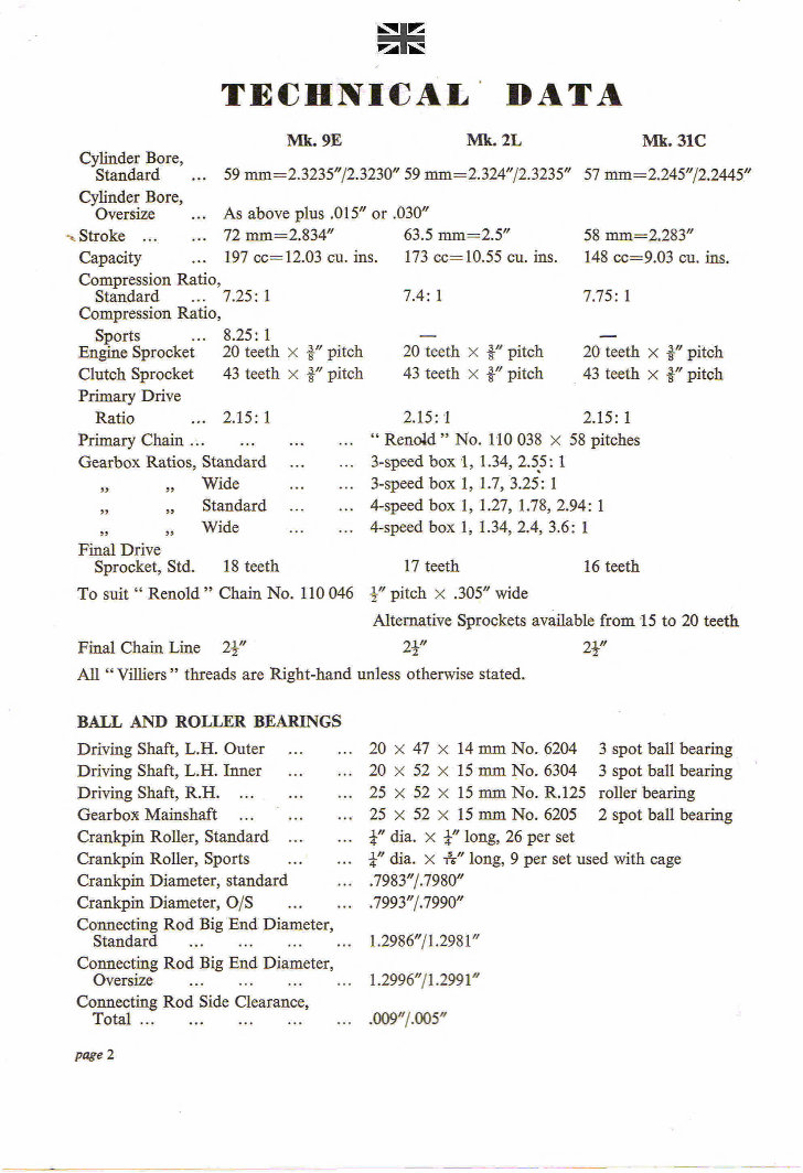
I/ II ■ • TECHNICAL DATA Cylinder Bore, Standard ... Cylinder Bore, Oversize ... Mk. 9E Mk. 2L 59 mm=2.3235"/2.3230" 59 mm=2.324"/2.3235" As above plus .015" or .030" Mk. 31C 57 mm=2.245"/2.2445" Stroke ... ... 72 mm=2.834" 63.5 mm=2.5" 58 mm=2.283" Capacity ... 197 cc= 12.03 Cu. ins. 173 cc= 10.55 Cu. ins. 148 cc---9.03 cu. ins. Compression Ratio, Standard ... 7.25: 1 7.4: 1 7.75: 1 Compression Ratio, Sports ... 8.25: 1 Engine Sprocket 20 teeth x i" pitch 20 teeth x i" pitch 20 teeth x ir pitch Clutch Sprocket 43 teeth x i" pitch 43 teeth x i" pitch 43 teeth x i" pitch Primary Drive Ratio ... 2.15: 1 2.15:'! 2.15: 1 Primary Chain ... " Rend(' " No. 110 038 x 58 pitches Gearbox Ratios, Standard ... 3-speed box 1, 1.34, 2.5 .5: 1 ff „ „ ff „ Wide Standard ... Wide . 3-speed box 1, 1.7, 3.25: 1 4-speed box 1, 1.27, 1.78, 2.94: 1 4-speed box 1, 1.34, 2.4, 3.6: 1 Final Drive Sprocket, Std. 18 teeth 17 teeth 16 teeth To suit " Renold " Chain No. 110 046 3 : " pitch x .305" wide Alternative Sprockets available from 15 to 20 teeth Final Chain Line 24" 24" 21" All " Villiers " threads are Right-hand unless otherwise stated. BALL AND ROLLER BEARINGS Driving Shaft, L.H. Outer ... Driving Shaft, L.H. Inner ... Driving Shaft, R.H. Gearbox Mainshaft Crankpin Roller, Standard ... Crankpin Roller, Sports Crankpin Diameter, standard Crankpin Diameter, 0/S Connecting Rod Big End Diameter, Standard ... Connecting Rod Big End Diameter, Oversize Connecting Rod Side Clearance, Total ... 20 x 47 x 14 mm No. 6204 3 spot ball bearing 20 x 52 x 15 mm No. 6304 3 spot ball bearing 25 x 52 x 15 mm No. R.125 roller bearing 25 x 52 x 15 mm No. 6205 2 spot ball bearing r dia. x r long, 26 per set +." dia. x TV," long, 9 per set used with cage .7983"/.7980" .7993"/.7990" 1.2986"/1.2981" 1.2996/1.2991" .009"/.005" page 2
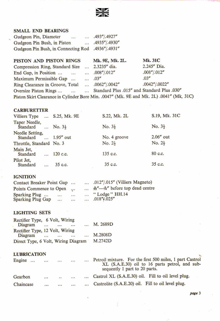
SMALL END BEARINGS _ Gudgeon Pin, Diameter ... .493"/.4927" Gudgeon Pin Bush, in Piston .4935"/.4930" Gudgeon Pin Bush, in Connecting Rod .4936"/.4931" PISTON AND PISTON RINGS Mk. 9E, Mk. 2L. Mk. 31C Compression Ring, Standard Size ... 2.3235" dia. 2.245" Dia. End Gap, in Position ... ... ... .008"/.012" .008"/.012" Maximum Permissible Gap ... ... .03" .03" Ring Clearance in Groove, Total .... 0062"/.0042" .0042"/.0022" Oversize Piston Rings ... ... ... Standard Plus .015" and Standard Plus .030" Piston Skirt Clearance in Cylinder Bore MM. .0047" (Mk. 9E and Mk. 2L) .0041" (Mk. 31C) CARBURETTER Villiers Type ... S.25, Mk. 9E S.22, Mk. 2L S.19, Mk. 31C Taper Needle, Standard ... No. 31 No. 31 No. 31 Needle Setting, Standard ... 1.95" out No. 4 groove 2.06" out Throttle, Standard No. 3 No. 24 No. 21 Main Jet, Standard ... 120 c.c. 135 c.c. 80 c.c. Pilot Jet, Standard ... 35 c.c. 35 c.c. 35 c.c. IGNITION Contact Breaker Point Gap ... Points Commence to Open v . Sparking Plug ... Sparking Plug Gap ... .012"/.015" (Villiers Magneto) iy"—*" before top dead centre " Lodge " HH.14 .018"i.025" LIGHTING SETS Rectifier Type, 6 Volt, Wiring Diagram ... ... M. 2689D Rectifier Type, 12 Volt, Wiring Diagram ... M.2808D Direct Type, 6 Volt, Wiring Diagram M.2742D LUBRICATION Engine ... Gearbox Chaincase Petroil mixture. For the first 500 miles, 1 part Castro] XL (S.A.E.30) oil to 16 parts petrol, and sub- sequently 1 part to 20 parts. Castrol XL (S.A.E.30) oil. Fill to oil level plug. ... Castrate (S.A.E.20) oil. Fill to oil level plug. page 3
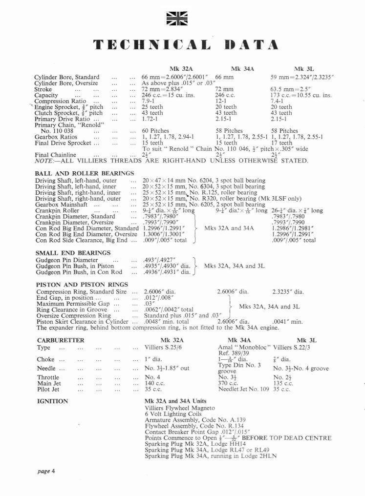
TECHNICAL DATA Mk 32A Mk 34A Mk 3L Cylinder Bore, Standard ... ... 66 mm=2.6006"/2.6001' 66 mm 59 nun=2.324"/2.3235" Cylinder Bore, Oversize ... ... As above plus .015" or .03" Stroke ... ... ... ... 72 mm=2.834" 72 mm 63.5 mm=2.5" Capacity -. ... ... 246 c.c.=15 Cu. ins. 246 c.c. 173 c.c. =10.55 cu. ins. Compression Ratio ... ...... 7.9-1 12-1 7.4-1 ' Engine Sprocket, 5' pitch ... ... 25 teeth 20 teeth 20 teeth Clutch Sprocket, II' pitch ... ... 43 teeth 43 teeth 43 teeth Primary Drive Ratio ... ... ... 1.72-1 2.15-1 2.15-1 Primary Chain, "Renold" No. 110 038 ... ...... 60 Pitches 58 Pitches 58 Pitches Gearbox Ratios ... ... ... I, 1.27, 1.78, 2.94-1 1, 1.27, 1.78, 2.55-1 1, 1.27, 1.78, 2.55-1 Final Drive Sprocket ... ... ... 15 teeth 15 teeth 17 teeth To suit " Renold " Chain No. 110 046, 5" pitch x .305" wide Final Chainline — 25" 24' 24' NOTE:—ALL VILLIERS THREADS ARE RIGHT-HAND UNLESS OTHERWISE STATED. BALL AND ROLLER BEARINGS Driving Shaft, left-hand, outer ... 20 x47 x 14 mm No. 6204, 3 spot ball bearing Driving Shaft, left-hand, inner ... 20 x 52 x 15 mm, No. 6304, 3 spot ball bearing Driving Shaft, right-hand, inner ... 25 x 52 x 15 mmu No. R.125, roller bearing Driving Shaft, right-hand, outer ... 20 x52 x 15 mm, No. R320, roller bearing (Mk 3LSF only) Gearbox Mainshaft ... — .-- 25 x 52 x 15 mm, No. 6205, 2 spot ball bearing Crankpin Roller ... ... ... 94" dia. x 1 5 6-' Ion 94' diW x -116-" long 264" dia. x 4' long Crankpin Diameter, Standard ... .7983"/.7980" .7983"/.7980 Crankpin Diameter, Oversize ... .7993"/.7990" I .7993"/.7990 Con Rod Big End Diameter, Standard 1.2996"/1.2991' Mks 32A and 34A 1.2986"/1.2981" Con Rod Big End Diameter, Oversize 1.3006/1.3001" I 1.2996'/1.2991" Con Rod Side Clearance, Big End ... .009"/.005" total J .009'7.005" total SMALL END BEARINGS Gudgeon Pin Diameter ... .493"/.4927' Gudgeon Pin Bush, in Piston ... .4935"/.4930' dia. Mks 32A, 34A and 3L Gudgeon Pin Bush, in Con Rod ... .4936'7.4931' dia. PISTON AND PISTON RINGS Compression Ring, Standard Size ... 2.6006" dia. 2.6006' dia. 2.3235' dia. End Gap, in position ... .012"/.008" Maximum Permissible Gap ... .03" Mks 32A, 34A and 3L Ring Clearance in Groove ... .0062'7.0042" total Oversize Compression Ring ... Standard plus .015" and .03" Piston Skirt Clearance in Cylinder ....0048' min. total 2.6006" dia. .0041' min. The expander ring, behind bottom compression ring, is not fitted to the Mk 34A engine. CARBURETTER Type ... ... ... Mk 32A Mk 34A Mk 3L ... ... Villiers S.25/6 Amal " Monobloc" Villiers S.22/3 Ref. 389/39 Choke ... ... ... ... ... 1" dia. 1--*" dia. i" dia. Needle ... ... ... ... ... No. 34-1.85" out Type Din No. 3 No. 3I-No. 4 groove groove Throttle No. 34 No. 25 Main Jet ... ... ... ... 140 c.c. 370 c.c. 135 c.c. Pilot Jet Needlet Jet No. 109 35 c.c. IGNITION Mk 32A and 34A Units Villiers Flywheel Magneto 6 Volt Lighting Coils Armature Assembly, Code No. A.139 ' Flywheel Assembly, Code No. R.134 Contact Breaker Point Gap .0121.015' Points Commence to Open 4"-- 3 1-" BEFORE TOP DEAD CENTRE Sparking Plug Mk 32A, Lodge HH14 Sparking Plug Mk MA, Lodge RL47 or RL49 page 4 Sparking Plug Mk 34A, running in Lodge 2HLN
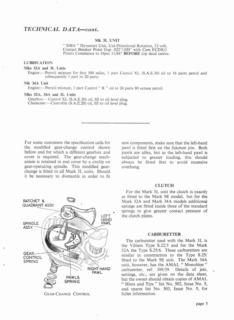
TECHNICAL DATA—cont. Mk 3L UNIT " SIBA " Dynastart Unit, Uni-Directional Rotation, 12 volt, Contact Breaker Point Gap .0227.020" with Cam FCDX/1 Points Commence to Open 11/64" BEFORE top dead centre. LUBRICATION Mks 32A and 3L Units Engine:—Petroil mixture for first 500 miles, 1 subsequently 1 part to 20 parts. part Castro! XL (S.A.E.30) oil to 16 parts petrol and Mk MA Unit Engine :—Petroil mixture, 1 part Castrol " R" oil to 24 parts 80 octane petrol. Mks 32A, MA and 3L Units Gearbox :—Castrol XL (S.A.E.30) oil, fill to oil level plug. Chaincase:—Castrolite (S.A.E.20) oil, fill to oil level plug. For some customers the specification calls for the modified gear-change control shown below and for which a different gearbox and cover is required. The gear-change mech- anism is retained in end cover by a circlip on gear-operating spindle. This modified gear- change is fitted to all Mark 3L units. Should it be necessary to dismantle in order to fit new components, make sure that the left-hand pawl is fitted first on the fulcrum pin. Both pawls are alike, but as the left-hand pawl is subjected to greater loading, this should always be fitted first to avoid excessive overhang. CLUTCH RATCHET & QUADRANT ASSY. SPINDLE ASSY. LEFT . • le% For the Mark 3L unit the clutch is exactly as fitted to the Mark 9E model, but for the Mark 32A and Mark 34A models additional springs are fitted inside three of the standard springs to give greater contact pressure of the clutch plates. CARBURETTER GEAR CONTROL SPRING ! . „N RIGHT HAND PAWL PAW LS SPRING GEAR-CHANGE CONTROL The carburetter used with the Mark 3L is the Villiers Type S.22/3 and for the Mark 32A the Type S.25/6. These carburetters are similar in construction to the Type S.25/ fitted to the Mark 9E unit. The Mark 34A unit, however, has the AMAL " Monobloc " carburetter, ref. 389/39. Details of jets, settings, etc., are given on the data sheet, but the owner should obtain copies of AMAL "Hints and Tips" list No. 502, Issue No. 5, and spares list No. 503, Issue No. 5, for fuller information. page 5
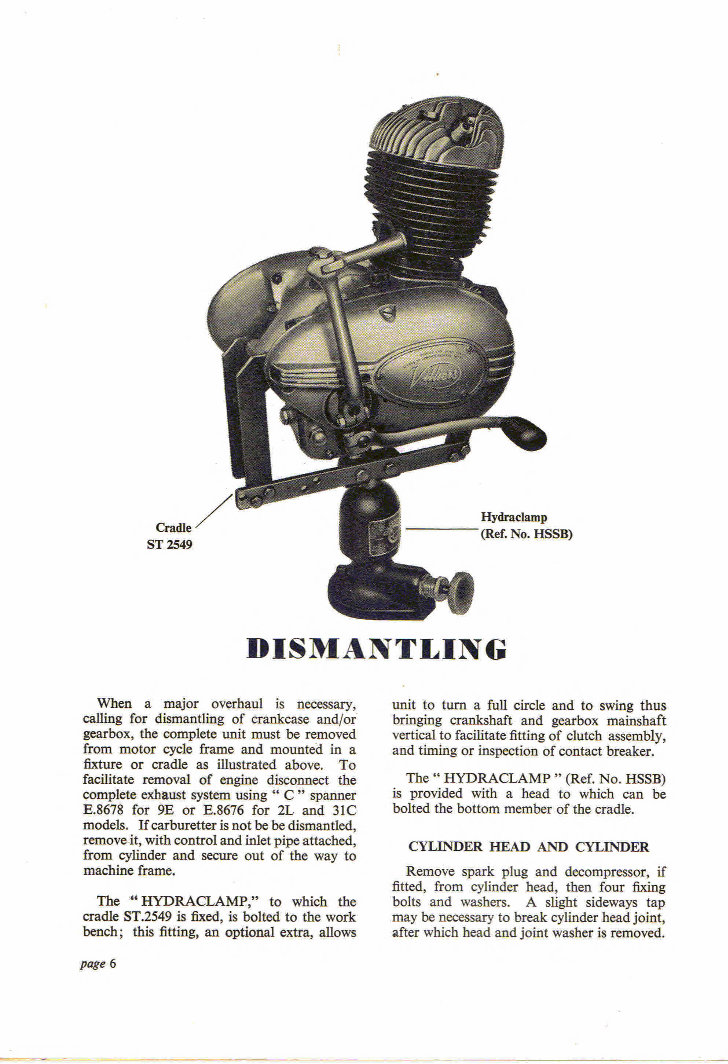
Cradle ST 2549 5SB) DISMANTLING When a major overhaul is necessary, calling for dismantling of crankcase and/or gearbox, the complete unit must be removed from motor cycle frame and mounted in a fixture or cradle as illustrated above. To facilitate removal of engine disconnect the complete exhaust system using " C " spanner E.8678 for 9E or E.8676 for 2L and 31C models. If carburetter is not be be dismantled, remove it, with control and inlet pipe attached, from cylinder and secure out of the way to machine frame. The " HYDRACLAMP," to which the cradle ST.2549 is fixed, is bolted to the work bench; this fitting, an optional extra, allows unit to turn a full circle and to swing thus bringing crankshaft and gearbox mainshaft vertical to facilitate fitting of clutch assembly, and timing or inspection of contact breaker. The " HYDRACLAMP " (Ref. No. HSSB) is provided with a head to which can be bolted the bottom member of the cradle. CYLINDER HEAD AND CYLINDER Remove spark plug and decompressor, if fitted, from cylinder head, then four fixing bolts and washers. A slight sideways tap may be necessary to break cylinder head joint, after which head and joint washer is removed. page 6
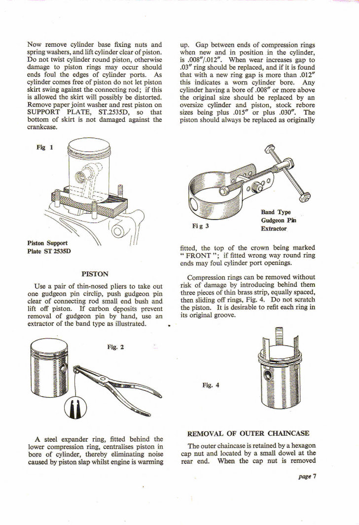
Now remove cylinder base fixing nuts and spring washers, and lift cylinder clear of piston. Do not twist cylinder round piston, otherwise damage to piston rings may occur should ends foul the edges of cylinder ports. As cylinder comes free of piston do not let piston skirt swing against the connecting rod; if this is allowed the skirt will possibly be distorted. Remove paper joint washer and rest piston on SUPPORT PLATE, ST.2535D, so that bottom of skirt is not damaged against the crankcase. Fig 1 ---------. Piston Support 1 Plate ST 253513 PISTON Use a pair of thin-nosed pliers to take out one gudgeon pin circlip, push gudgeon pin clear of connecting rod small end bush and lift off piston. If carbon dposits prevent removal of gudgeon pin by hand, use an extractor of the band type as illustrated. , ■. 41111 1,._M Fig. 2 s----- ----_---- — N. S - , 1 '-- L -= ' --.. a- - II %... , 4 4.4........._ M , A steel expander ring, fitted behind the lower compression ring, centralises piston in bore of cylinder, thereby eliminating noise caused by piston slap whilst engine is warming up. Gap between ends of compression rings when new and in position in the cylinder, is .008"/.012". When wear increases gap to .03" ring should be replaced, and if it is found that with a new ring gap is more than .012" this indicates a worn cylinder bore. Any cylinder having a bore of .008" or more above the original size should be replaced by an oversize cylinder and piston, stock rebore sizes being plus .015" or plus .030". The piston should always be replaced as originally Fi g 3 Extractor fitted, the top of the crown being marked "FRONT "; if fitted wrong way round ring ends may foul cylinder port openings. Compression rings can be removed without risk of damage by introducing behind them three pieces of thin brass strip, equally spaced, then sliding off rings, Fig. 4. Do not scratch the piston. It is desirable to refit each ring in its original groove. REMOVAL OF OUTER CHA1NCASE The outer chaincase is retained by a hexagon cap nut and located by a small dowel at the rear end. When the cap nut is removed page 7
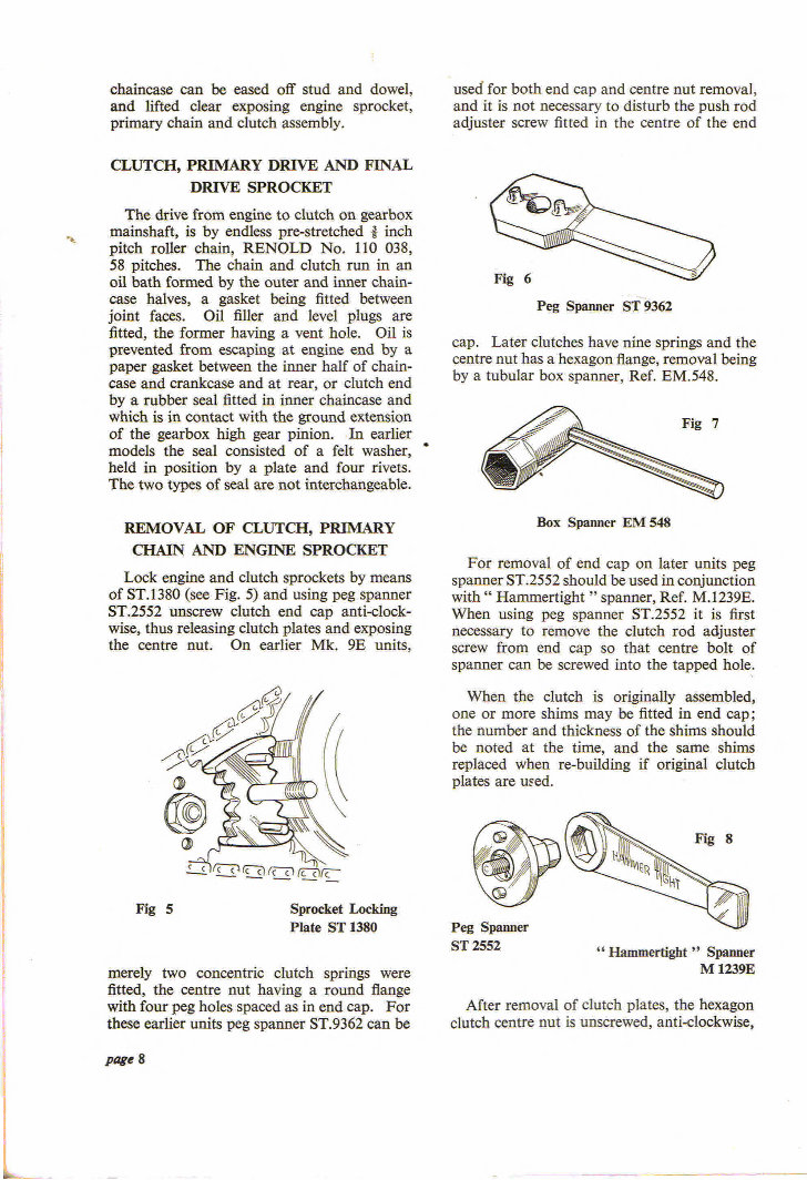
used for both end cap and centre nut removal, and it is not necessary to disturb the push rod adjuster screw fitted in the centre of the end chaincase can be eased off stud and dowel, and lifted clear exposing engine sprocket, primary chain and clutch assembly. CLUTCH, PRIMARY DRIVE AND FINAL DRIVE SPROCKET The drive from engine to clutch on gearbox mainshaft, is by endless pre-stretched .11 inch pitch roller chain, RENOLD No. 110 038, 58 pitches. The chain and clutch run in an oil bath formed by the outer and inner chain- case halves, a gasket being fitted between joint faces. Oil filler and level plugs are fitted, the former having a vent hole. Oil is prevented from escaping at engine end by a paper gasket between the inner half of chain- case and crankcase and at rear, or clutch end by a rubber seal fitted in inner chaincase and which is in contact with the ground extension of the gearbox high gear pinion. In earlier models the seal consisted of a felt washer, held in position by a plate and four rivets. The two types of seal are not interchangeable. REMOVAL OF CLUTCH, PRIMARY CHAIN AND ENGINE SPROCKET Lock engine and clutch sprockets by means of ST.1380 (see Fig. 5) and using peg spanner ST.2552 unscrew clutch end cap anti-clock- wise, thus releasing clutch plates and exposing the centre nut. On earlier Mk. 9E units, Fig 5 Sprocket Locking Plate ST 1380 merely two concentric clutch springs were fitted, the centre nut having a round flange with four peg holes spaced as in end cap. For these earlier units peg spanner ST.9362 can be 14141401\191 Fig 6 Peg Spanner ST 9362 cap. Later clutches have nine springs and the centre nut has a hexagon flange, removal being by a tubular box spanner, Ref. EM.548. : i8 7 , -- ''''''''' ■.,... - -- -- - -- --4 Box Spanner EM 548 For removal of end cap on later units peg spanner ST.2552 should be used in conjunction with" Hammertight "spanner, Ref. M.1239E. When using peg spanner ST.2552 it is first necessary to remove the clutch rod adjuster screw from end cap so that centre bolt of spanner can be screwed into the tapped hole. When the clutch is originally assembled, one or more shims may be fitted in end cap; the number and thickness of the shims should be noted at the time, and the same shims replaced when re-building if original clutch plates are used. - \ ) , ;, ,. . t, 111) 1.4 -• ctl eilL d s• -w . 1/ ' I Peg Spanner ST 2552 " Hammertight " Spanner M 1239E After removal of clutch plates, the hexagon clutch centre nut is unscrewed, anti-clockwise, Page 8
This workshop manual is designed for Villiers mechanics, engine restorers, and general Villiers owners. It is a popular manual that is suitable for a wide range of engines, including those found in Greeves, Dot, Francis Barnett, Sun, Ambassador, Bond, Butler, Cotton, Dayton, DkR, DMW, Excelsior, James, Norman, Panther, Phoenix, Scorpion, Sprite, and more.
It is a dated 1962 manual from the Official Villiers workshop manuals, featuring good quality print and easy-to-read content. The manual includes the following contents:
Forward section
Technical Data: Sizes, Settings, Tolerances
Dismantling the engine
Rebuilding the unit
The competition gear unit
9E Cart engines
With 30 pages, this manual provides all the necessary information for repairing Villiers engines. It is an invaluable resource for both professional mechanics and DIY enthusiasts, serving as an instant and hard-to-find manual.