

Workshop Repair Parts manual catalog 1NZ-FE engine
What's Included?
Fast Download Speeds
Online & Offline Access
Access PDF Contents & Bookmarks
Full Search Facility
Print one or all pages of your manual
1NZ-FE ENGINE MECHANICAL – ENGINE
EM–1
EM
ENGINE
ON-VEHICLE INSPECTION
1. INSPECT ENGINE COOLANT (See page CO-1)
2. INSPECT ENGINE OIL (See page LU-1)
3. INSPECT BATTERY (See page CH-4)
4. INSPECT AIR CLEANER FILTER ELEMENT SUB-
ASSEMBLY
(a) Remove the air cleaner filter element sub-assembly.
(b) Visually check that there is no dirt, blockage, or
damage to the air cleaner filter element.
HINT:
• If there is any dirt or a blockage in the air cleaner
filter element, clean it with compressed air.
• If any dirt or a blockage remains even after
cleaning the air cleaner filter element with
compressed air, replace it.
5. INSPECT SPARK PLUG (See page IG-5)
6. INSPECT IGNITION TIMING
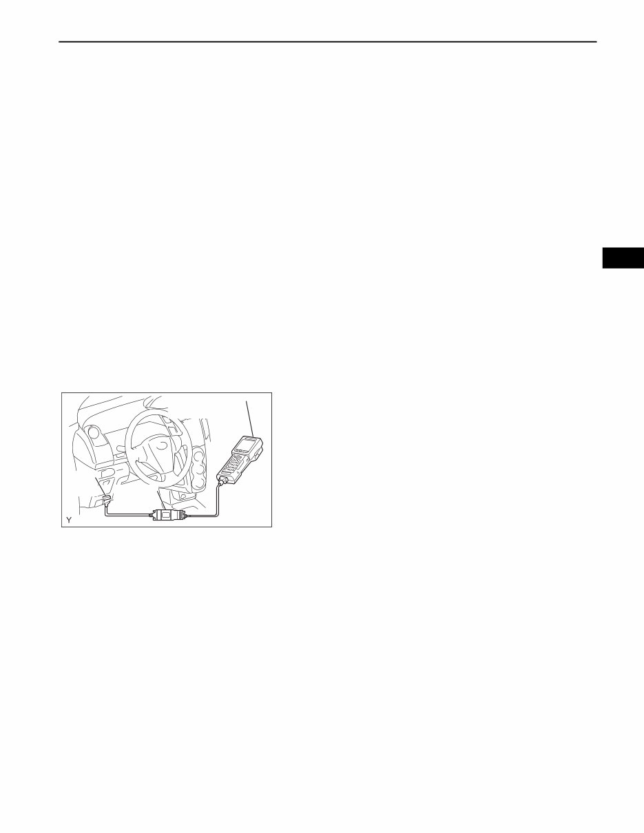
(a) When using an intelligent tester:
(1) Warm up and stop the engine.
(2) Connect the intelligent tester to the DLC3.
(3) Turn the ignition switch ON.
(4) Select the following menu items:
DIAGNOSIS / ENHANCED OBD II/ ACTIVE
TEST / TC (TE1) / ON.
HINT:
Refer to the intelligent tester operator's manual
for further details.
(5) Inspect the ignition timing during idling.
Ignition timing:
8 to 12 degrees BTDC
NOTICE:
• Turn all the electrical systems and the A/
C off.
• Inspect the ignition timing with the
cooling fan off.
• When checking the ignition timing, shift
the transmission to the neutral position.
(6) Select the following menu items: TC (TE1) /
OFF.
(7) Turn the ignition switch OFF.
(8) Disconnect the intelligent tester from the DLC3.
(b) When not using an intelligent tester:
(1) Remove cylinder head cover No. 2 (see page
IG-9).
DLC3
Intelligent Tester
CAN VIM
A125658E01
EM–2
1NZ-FE ENGINE MECHANICAL – ENGINE
EM
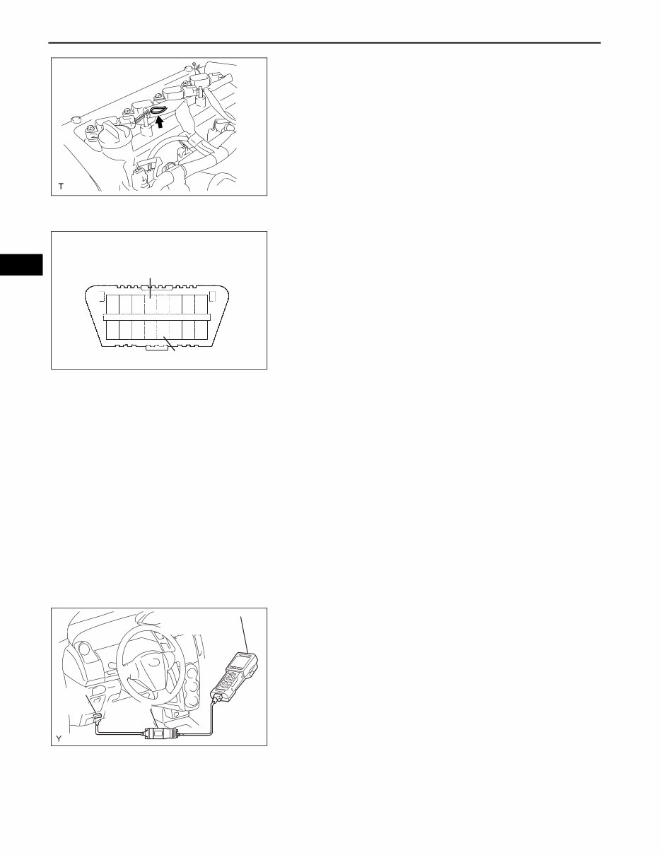
(2) Pull out the wire harness (brown) shown in the
illustration.
NOTICE:
After checking, wrap the wire harness with
tape.
(3) Warm up and stop the engine.
(4) Connect the clip of the timing light to the wire
harness.
NOTICE:
Use a timing light that detects the first
signal.
(5) Turn the ignition switch ON.
(6) Using SST, connect terminals 13 (TC) and 4
(CG) of the DLC3.
SST 09843-18040
NOTICE:
Examine the terminal numbers before
connecting them. Connecting the wrong
terminals could damage the engine.
(7) Inspect the ignition timing during idling.
Ignition timing:
8 to 12 degrees BTDC
NOTICE:
• Turn all the electrical systems and the A/
C off.
• Inspect the ignition timing with the
cooling fan off.
• When checking the ignition timing, shift
the transmission to the neutral position.
(8) Disconnect terminals 13 (TC) and 4 (CG) of the
DLC3.
(9) Turn the ignition switch OFF.
(10) Remove the timing light.
(11) Install cylinder head cover No. 2 (see page IG-
10).
7. INSPECT ENGINE IDLING SPEED
(a) When using an intelligent tester:
(1) Warm up and stop the engine.
(2) Connect the intelligent tester to the DLC3.
(3) Turn the ignition switch ON.
(4) Select the following menu items:
DIAGNOSIS / ENHANCED OBD II/ DATA LIST
/ PRIMARY / ENGINE SPD.
HINT:
Refer to the intelligent tester operator's manual
for further details.
(5) Inspect the engine idling speed.
Idling speed:
550 to 650 rpm for manual transaxle
650 to 750 rpm for automatic transaxle
NOTICE:
• Turn all the electrical systems and the A/
C off.
A116196
1 23456 78
9 10111213141516
DLC3
CG
TC
A082779E23
DLC3
Intelligent Tester
CAN VIM
A125658E01
1NZ-FE ENGINE MECHANICAL – ENGINE
EM–3
EM
• Inspect the idling speed with the cooling
fan off.
• When checking the idling speed, shift the
transmission to either the neutral
position or the parking position.
(6) Turn the ignition switch OFF.
(7) Disconnect the intelligent tester from the DLC3.
(b) When not using an intelligent tester.
(1) Warm up and stop the engine.
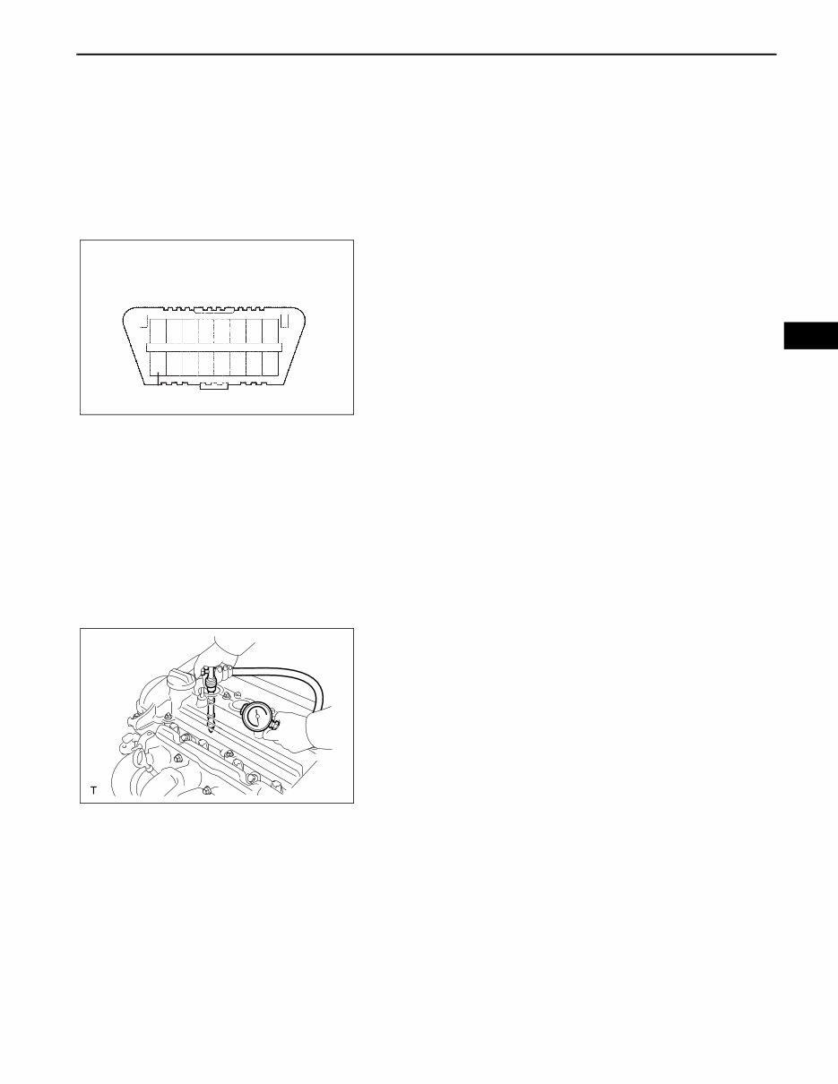
(2) Install SST to terminal 9 (TAC) of the DLC3,
then connect a tachometer.
SST 09843-18040
NOTICE:
Examine the terminal numbers before
connecting them. Connecting the wrong
terminals could damage the engine.
(3) Turn the ignition switch ON.
(4) Inspect the engine idling speed.
Idling speed:
550 to 650 rpm for manual transaxle
650 to 750 rpm for automatic transaxle
(5) Turn the ignition switch OFF.
(6) Disconnect the tachometer.
(7) Remove SST from terminal 9 (TAC).
8. INSPECT COMPRESSION
(a) Warm up and stop the engine.
(b) Remove cylinder head cover No. 2 (see page IG-9).
(c) Remove the 4 ignition coils (see page IG-9).
(d) Remove the 4 spark plugs.
(e) Disconnect the 4 fuel injector connectors.
(f) Inspect the cylinder compression pressure.
(1) Insert a compression gauge into the spark plug
hole.
(2) Fully open the throttle.
(3) While cranking the engine, measure the
compression pressure.
Compression:
1,471kPa (15.0 kgf/cm
2
, 213 psi)
Minimum pressure:
1,079 kPa (11.0 kgf/cm
2
, 156 psi)
Difference between each cylinder:
98 kPa (1.0 kgf/cm
2
, 14 psi) or less
NOTICE:
• Use a fully-charged battery so the engine
speed can be increased to 250 rpm or
more.
• Inspect the other cylinders in the same
way.
• Measure the compression in as short a
time as possible.
9 10111213141516
DLC3
TAC
12345678
A082779E24
A116195

EM–4
1NZ-FE ENGINE MECHANICAL – ENGINE
EM
(4) If the cylinder compression is low, pour a light
coat of engine oil into the cylinder through the
spark plug hole, then inspect it again.
HINT:
• If adding oil increases the compression, the
piston rings and/or cylinder bore may be
worn or damaged.
• If the pressure stays low, the valve may be
stuck or seated improperly, or there may be
leakage from the gasket.
(g) Connect the 4 fuel injector connectors.
(h) Install the 4 spark plugs.
Torque: 18 N*m (184 kgf*cm, 13 ft.*lbf)
(i) Install the 4 ignition coils (see page IG-9).
(j) Install cylinder head cover No. 2 (see page IG-10).
9. INSPECT CO/HC
(a) Start the engine.
(b) Run the engine at 2,500 rpm for approximately 180
seconds.
(c) Insert the CO/HC meter testing probe at least 40 cm
(1.3 ft) into the tailpipe while idling.
(d) Check the CO/HC concentration during idling and
when running at 2,500 rpm.
HINT:
When doing the 2 mode (with the engine idling/
running at 2,500 rpm) test, the measuring
procedures are determined by applicable local
regulations.
If the CO/HC concentration does not comply with
the regulations, troubleshoot in the order given
below.
(1) Check the heated oxygen sensor operation
(see page ES-276).
(2) See the table below for possible causes, then
inspect the applicable parts and repair them if
necessary.
CO HC Problems Possible Causes
Normal High Rough idling 1. Faulty ignition:
– Incorrect timing
– Fouled, shorted or improperly gapped plugs
2. Incorrect valve clearance
3. Leakage from intake and exhaust valves
4. Leakage from cylinders
Low High Rough idling
(Fluctuating HC reading)
1. Vacuum leaks:
– PCV hoses
– Intake manifold
– Throttle body
– Brake booster line
2. Lean mixture causing misfire
High High Rough idling
(Black smoke from exhaust)
1. Restricted air cleaner filter element
2. Plugged PCV valve
3. Faulty EFI systems:
– Faulty pressure regulator
– Faulty engine coolant temperature sensor
– Faulty mass air flow meter
– Faulty ECM
– Faulty injectors
– Throttle body
1NZ-FE ENGINE MECHANICAL – DRIVE BELT
EM–5
EM
ENGINE 1NZ-FE ENGINE MECHANICAL
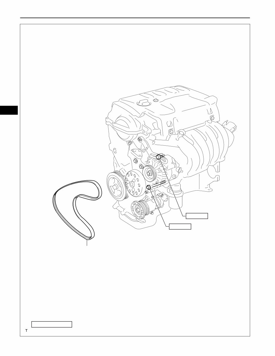
DRIVE BELT
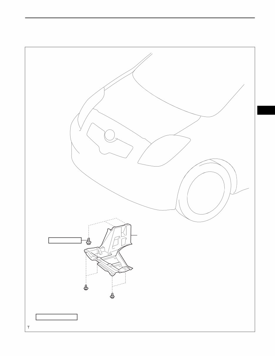
COMPONENTS
5.0 (51, 44 in.*lbf)
N*m (kgf*cm, ft.*lbf) : Specified torque
ENGINE UNDER COVER RH
A115143E01
EM–6
1NZ-FE ENGINE MECHANICAL – DRIVE BELT
EM
FAN AND GENERATOR V BELT
N*m (kgf*cm, ft.*lbf) : Specified torque
54 (551, 40)
19 (189, 14)
A116199E01
1NZ-FE ENGINE MECHANICAL – DRIVE BELT
EM–7
EM
REMOVAL
1. REMOVE ENGINE UNDER COVER RH
2. REMOVE FAN AND GENERATOR V BELT
(a) Loosen bolts A and B.
(b) Release the fan and generator V belt tension and
remove the fan and generator V belt.
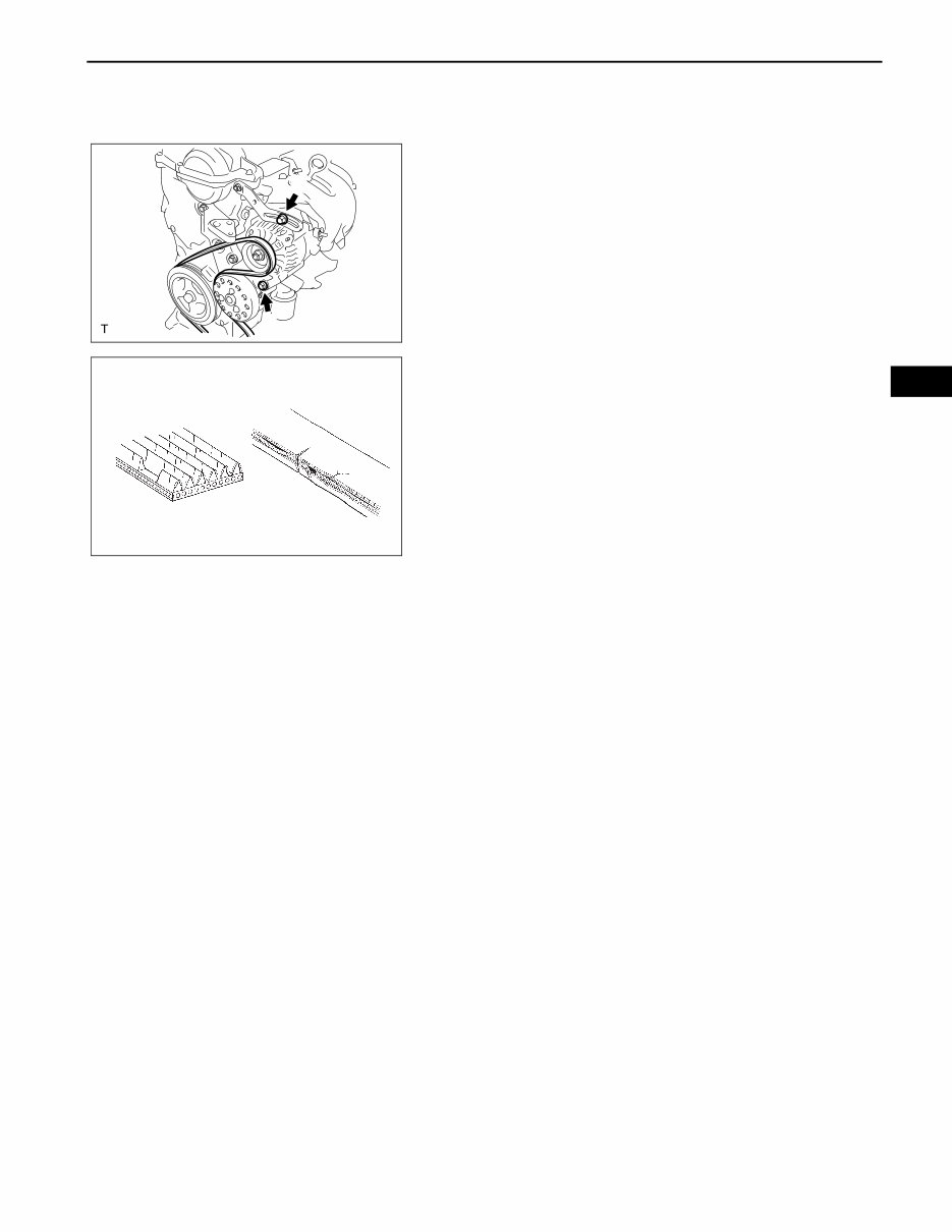
INSPECTION
1. INSPECT FAN AND GENERATOR V BELT
(a) Visually check the belt for excessive wear, frayed
cords etc. If any defects are found, replace the belt.
HINT:
• If any defects are found, replace the belt.
• Cracks on the rib side of a belt are considered
acceptable. If the belt has pieces missing from
the ribs, it should be replaced.
A
B
A116197E01
B000543
EM–8
1NZ-FE ENGINE MECHANICAL – DRIVE BELT
EM
INSTALLATION
1. INSTALL FAN AND GENERATOR V BELT
(a) Provisionally install the fan and generator V belt
onto each pulley.
NOTICE:
Make sure that the V-belt is securely fitted into
the rib groove of the pulley.
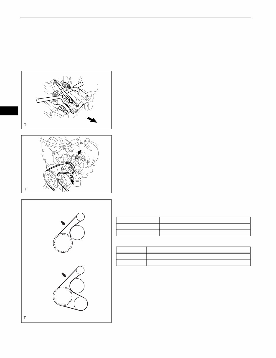
2. ADJUST FAN AND GENERATOR V BELT
(a) Insert an adjusting bar between the engine
mounting bracket and generator assembly. Push the
adjusting bar toward the vehicle front to adjust the
generator V belt tension.
NOTICE:
Do not insert the adjusting bar between the
camshaft timing oil control valve assembly and
generator assembly. It could damage the
camshaft timing oil control valve assembly.
(b) First tighten bolt A, then tighten bolt B.
Torque: 19 N*m (189 kgf*cm, 14 ft.*lbf) for bolt A
54 N*m (551 kgf*cm, 40 ft.*lbf) for bolt B
3. INSPECT FAN AND GENERATOR V BELT
(a) Check the V belt deflection and tension.
Deflection
Tension
If the belt deflection is not as specified, adjust it.
HINT:
• Check the V belt deflection at the specified point.
• Check the drive belt deflection at the specified
point.
• When installing a new belt, set its tension to the
specified value.
• When inspecting a belt which has been used for
over 5 minutes, apply the used belt
specifications.
NG
OK
A116198E01
A
B
A116197E01
w/o Air Conditioner
w/ Air Conditioner
A116200E01
Item Specified Condition
New belt 7.0 to 8.5 mm (0.28 to 0.33 in)
Used belt 11 to 13 mm (0.43 to 0.51 in)
Item Specified Condition
New belt 539 to 637 N (55 to 65 kg, 121 to 143 ld)
Used belt 245 to 392 N (25 to 40 kg, 55 to 88 ld)

1NZ-FE ENGINE MECHANICAL – DRIVE BELT
EM–9
EM
• When reinstalling a belt which has been used for
over 5 minutes, adjust its deflection and tension
to the intermediate values of each used belt
specification.
• V-ribbed belt tension and deflection should be
checked after 2 revolutions of engine cranking.
• When using a belt tension gauge, confirm its
accuracy by using a master gauge first.
4. INSTALL ENGINE UNDER COVER RH
1NZ-FE ENGINE MECHANICAL – VALVE CLEARANCE
EM–9
EM
VALVE CLEARANCE
ADJUSTMENT
1. DISCONNECT CABLE FROM NEGATIVE BATTERY
TERMINAL
2. REMOVE ENGINE UNDER COVER RH
3. REMOVE CYLINDER HEAD COVER NO. 2 (See page
IG-9)
4. REMOVE IGNITION COIL NO. 1 (See page IG-9)
5. DISCONNECT VENTILATION HOSE (See page FU-13)
6. DISCONNECT VENTILATION HOSE NO. 2 (See page
FU-13)
7. REMOVE CYLINDER HEAD COVER SUB-ASSEMBLY
(See page FU-13)
8. INSPECT VALVE CLEARANCE
HINT:
Inspect the valve clearance when the engine is cold.
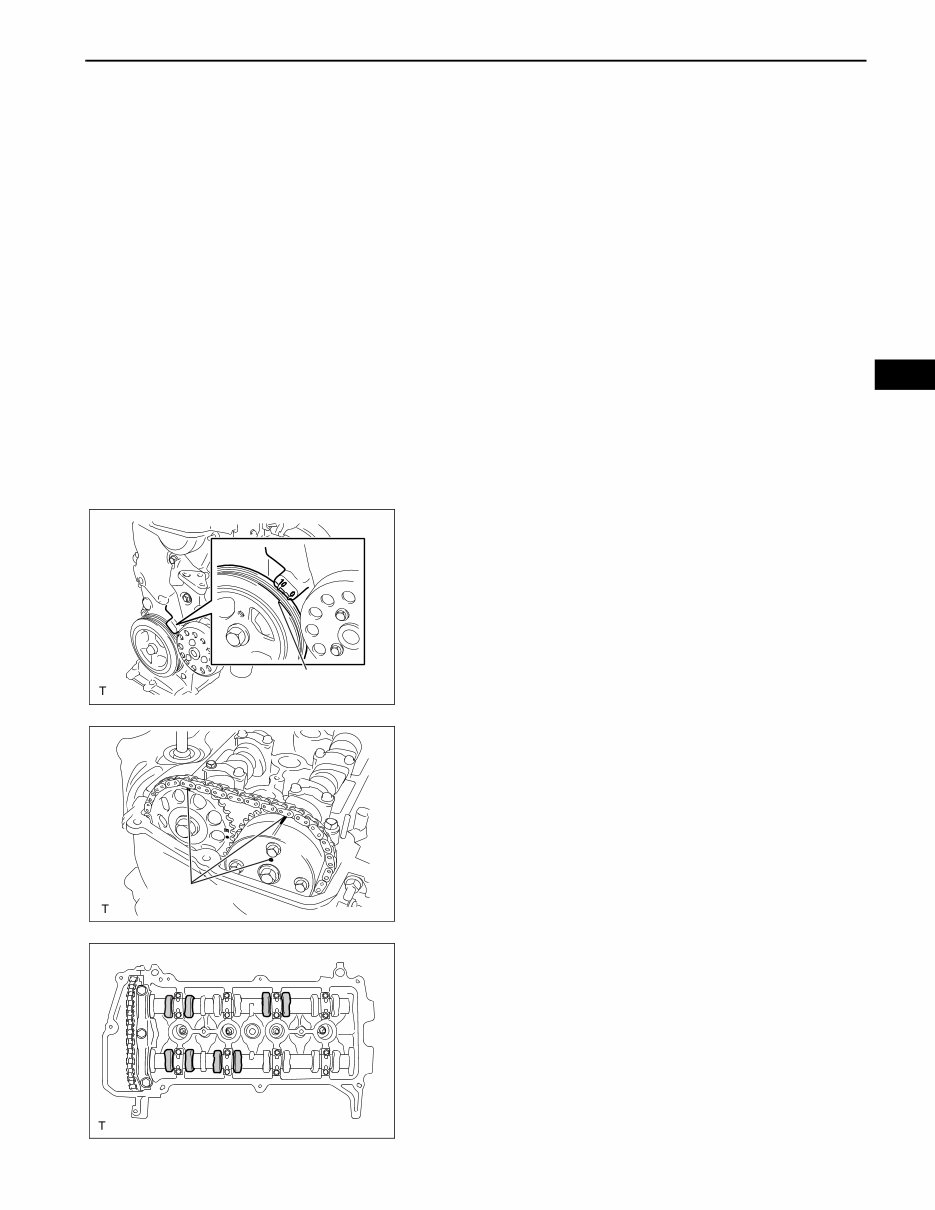
(a) Set the No. 1 cylinder to TDC/compression.
(1) Turn the crankshaft damper and align its timing
notch with the timing mark "0" of the oil pump.
(2) Check that both timing marks on the camshaft
timing sprocket and camshaft timing gear are
facing upward, as shown in the illustration.
HINT:
If not, turn the crankshaft 1 complete revolution
(360°) and align the marks as above.
(b) Check the valves indicated in the illustration.
(1) Using a feeler gauge, measure the clearance
between the valve lifter and camshaft.
Valve clearance (cold):
for intake:
0.15 to 0.25 mm (0.006 to 0.010 in.)
for exhaust:
0.25 to 0.35 mm (0.010 to 0.014 in.)
Timing Notch
A116203E01
Timing Marks
A116204E01
A116201
You're Reading a Preview
What's Included?
Fast Download Speeds
Online & Offline Access
Access PDF Contents & Bookmarks
Full Search Facility
Print one or all pages of your manual
$46.99
$61.99
Viewed 89 Times Today


Secure transaction
What's Included?
Fast Download Speeds
Online & Offline Access
Access PDF Contents & Bookmarks
Full Search Facility
Print one or all pages of your manual
$46.99
$61.99
If your vehicle uses the 1NZ-FE engine, this workshop and parts manual is essential for all your repair needs. Whether you are a professional mechanic or a DIY enthusiast, this manual provides comprehensive information for engine repair.
The 1NZ-FE engine is utilized in the following vehicles:


