

Toyota 7M-GE & 7M-GTE Engine Repair Manual
What's Included?
Fast Download Speeds
Online & Offline Access
Access PDF Contents & Bookmarks
Full Search Facility
Print one or all pages of your manual
TOYOb4 ‘.
REPAIR MANUAL
Downloaded from www.Manualslib.com manuals search engine
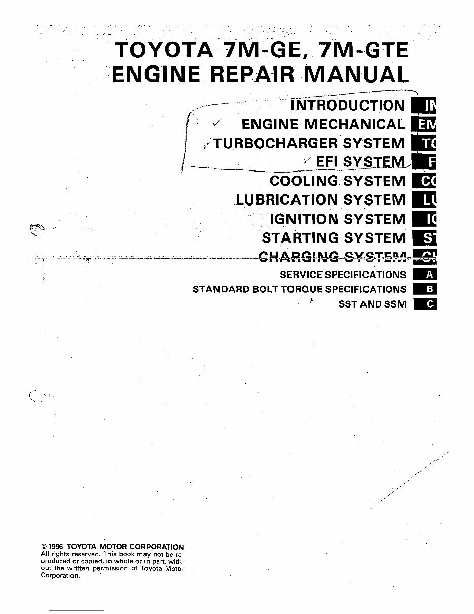
COOLtNG SYSTEM m
SYSTEM m
SVSTEM m
SYSTEM m
0 1996 TOYOTA MOTOR CORPORATION
All rights reserved. This book may not be re-
produced or copied, in whole or in part, with-
out the written permission of Toyota Motor
Corporation.
Downloaded from www.Manualslib.com manuals search engine
,. a,..
.,.,T
Pl9. :-, ,::::;:;:
HOW TO USE THIS MANUAL . . . , . , , . . . . . . . . . . . . .
IN-2
I
IDENTIFICATION INFORMATION . . . . . . . . . . . . . . . . . IN-4 m
GENERAL REPAIR INSTRUCTIONS . . . . . . z., . . . . a. IN-4 .
PRECAUTIONS FOR VEHICLES EQUIPPED WITH
A CATALYTIC CONVERTER . . . , . , . . . . . . . l . . . . . .
IN-6
ABBREVIATIONS USED IN THIS MANUAL . . . . . . . .
IN-7
,
Downloaded from www.Manualslib.com manuals search engine
IN-2 INTRODUiTlON - How to Use This Manual
._. ._. -,-. ..
.
HOW TO USE THIS MANUAL
To assist you in finding your way through this manual, the Set-
tion Title and major heading are given at the top of every page.
An INDEX is provided on the 1 st page of each section to guide
YOU to the item to be repaired.
At the beginning of each section, PRECAUTIONS are given
that pertain to al/repair operations contained in that section.
Read these precautions before starting any repair task.
TROUBLESHOOTING tables are included for each system to
help you diagnose the system problem and find the cause. The
repair for each possible cause is referenced in the remedy COI-
umn to quickly lead you to the solution.
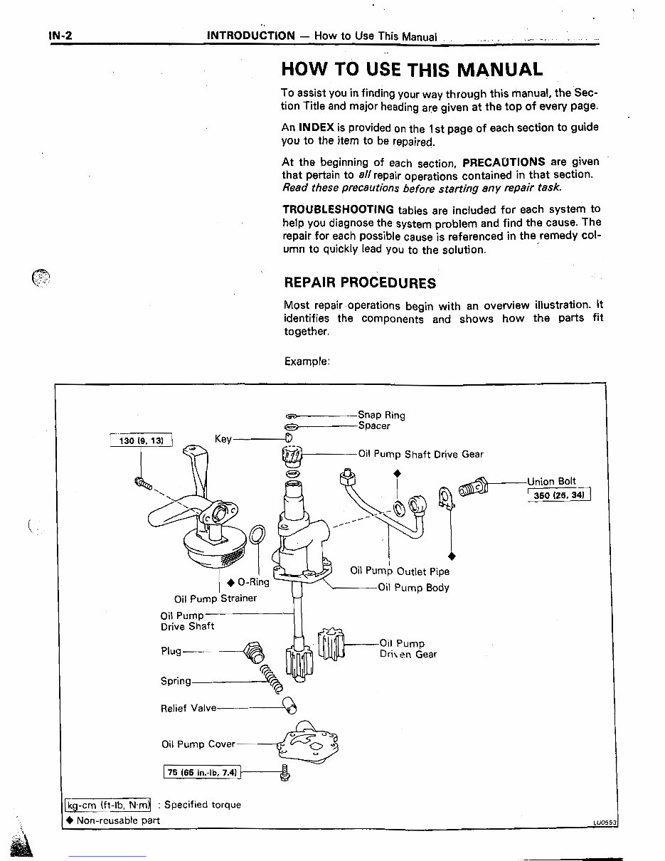
REPAIR PROCEDURES
Most repair operations begin with an overview illustration. lt
identifies the components and shows how the patiS fit
together.
Example:
Oil Pump Shaft Drive Gear
Oil Pump Outlet Pipe
Oil Pump Strainer
Drive Shaft
Relief Valve------Q
Oil Pump Cover------&
75 (65 in.-lb, 7.4)
-Union Bolt
(1
cg-cm (ft-lb, N.m : Specified torque
) Non-reusable part LUO5
Downloaded from www.Manualslib.com manuals search engine
INTROkJCT-iON - How to Use This Manual
I IN-3
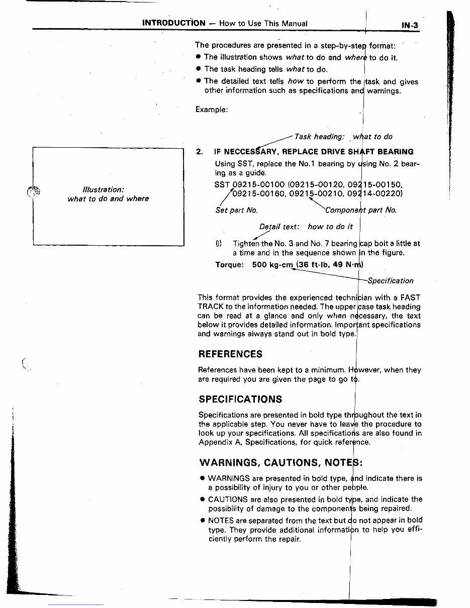
The procedures are presented in a step-by-ster format:
0 The illustration shows what to do and where to do it.
0 The task heading tells what to do.
0 The detailed text tells how to perform the task and gives
other information such as specifications and warnings.
Example:
J
/ Task heading: _ w at to do
tllus tra tion:
what to do and where
2. IF NECCESdY, REPLACE DRIVE SH FT BEARING
Using SST, replace the No.1 bearing by sing No. 2 bear-
ing as a guide.
SST 092 15-00100 (092 15-00120, 09 15-00150,
/ 092 1500160,092 15-002 10, 09 14-00220)
Set part No.
\
i
Compone t part No.
D&/ail text: how to do it
(i) Tightecthe No. 3 and No. 7 bearing cap bolt a little at
a time and in the sequence shown n the figure.
Torque: 500 kg-cm (36 ft-lb, 49 NW)
.-Specification
This format provides the experienced technician with a FAST
TRACK to the information needed. The upper case task heading
can be read at a glance and only when necessary, the text
below it provides detailed information. Impor:ant specifications
and warnings always stand out in bold type.
REFERENCES
References have been kept to a minimum. However, when they
are required you are given the page to go to.
SPECIFICATIONS
Specifications are presented in bold type
the applicable step. You never have to I
look up your specifications. All specifica
Appendix A, Specifications, for quick
WARNINGS, CAUTIONS, N
0 WARNINGS are presented in bold d indicate there is
a possibility of injury to you or ot
0 CAUTIONS are also presented in bold
possibility of damage to the compone
0 NOTES are separated from the text
type. They provide additional infor
ciently perform the repair.
Downloaded from www.Manualslib.com manuals search engine
IN-4
Identification Information,
INTRODUCTION - General Repair Instructions
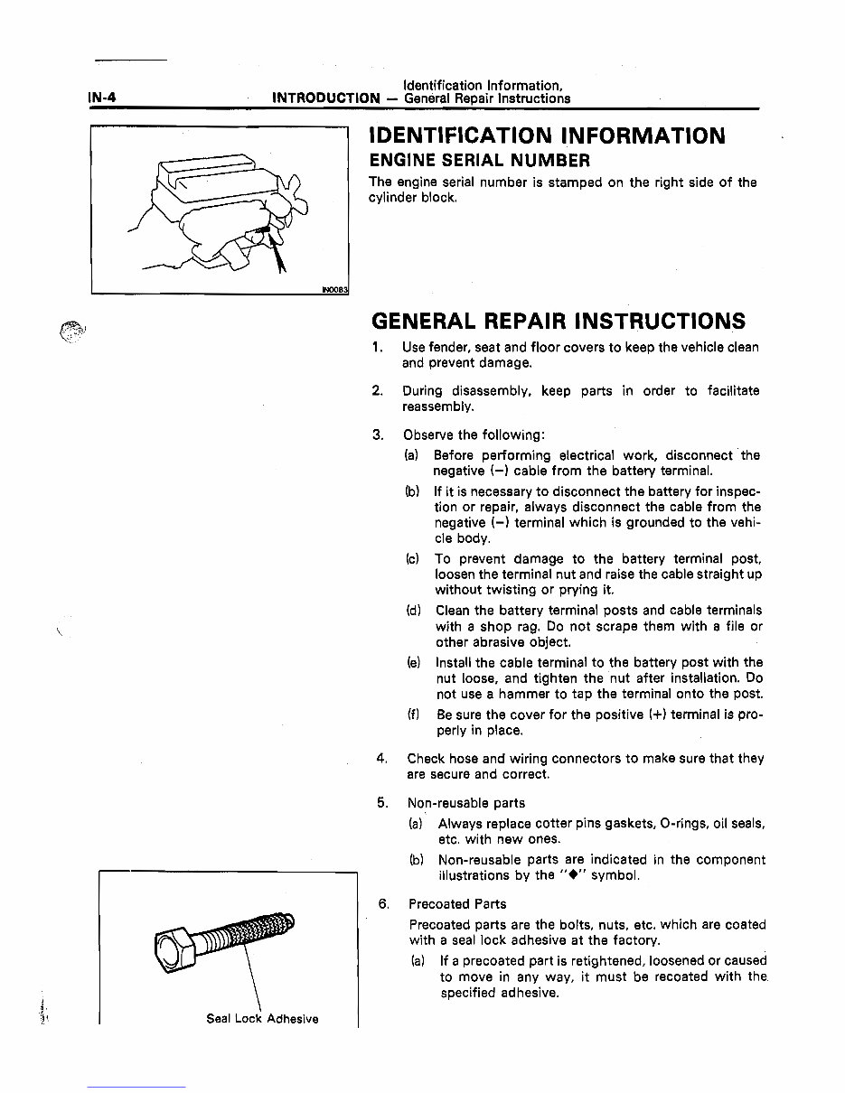
IDENTIFICATION INFORMATION
ENGINE SERIAL NUMBER
The engine serial number is stamped on the right side of the
cylinder block.
Seal Lock Adhesive
GENERAL REPAIR INSTRUCTIONS
1. Use fender, seat and floor covers to keep the vehicle clean
and prevent damage.
2.
3.
During disassembly, keep parts in order to facilitate
reassembly.
Observe the following:
(a)
(b)
Before performing electrical work, disconnect ‘the
negative (-1 cable from the battery terminal.
If it is necessary to disconnect the battery for inspec-
tion or repair, always disconnect the cable from the
negative (-) terminal which is grounded to the vehi-
cle body.
(c) To prevent damage to the battery terminal post,
loosen the terminal nut and raise the cable straight up
without twisting or prying it.
(d) Clean the battery terminal posts and cable terminals
with a shop rag. Do not scrape them with a file or
other abrasive object.
(e)
(f)
Install the cable terminal to the battery post with the
nut loose, and tighten the nut after installation. Do
not use a hammer to tap the terminal onto the post.
Be sure the cover for the positive (+I terminal is pro-
perly in place.
4.
5.
Check hose and wiring connectors to make sure that they
are secure and correct.
Non-reusable parts
Always replace cotter pins gaskets, O-rings, oil seals,
etc. with new ones.
(b) Non-reusable parts are indicated in the component
illustrations by the “+” symbol.
6. Precoated Parts
Precoated parts are the bolts, nuts, etc. which are coated
with a seal lock adhesive at the factory.
(a) If a precoated part is retightened, loosened or caused
to move in any way, it must be recoated with the
specified adhesive.
Downloaded from www.Manualslib.com manuals search engine
INTRODUCTION - General Repair Instructions
IN-S
(b) Recoating of Precoated Parts
(1) Clean off the old adhesive from the
threads.
(2) Dry with compressed air.
(3) Apply the specified seal lock adhesive to the
threads.
(c) Precoated parts are indicated in the component
illustrations by the “*” symbol.
7. When necessary, use a sealer or gaskets to prevent leaks.
8. Carefully observe all specifications for bolt torques.
Always use a torque wrench.
9. Use of special service tools (SST) and special service
materials (SSM) may be required, depending on the nature
of the repair. Be sure to use SST and SSM where specified
and follow the proper work procedure. A list of SST and
SSM can be found at the back of this manual.
10. When replacing fuses, be sure the new fuse is the correct
amperage. DO NOT exceed the fuse amp rating or use one
of a lower rating.
11. Care must be taken when jacking up and supporting the
vehicle. Be sure to lift and support the vehicle at the
proper locations.
(a) If the vehicle is to be jacked up only at the front or
rear end, be sure to block the wheels in order to
ensure safety.
(b) After the vehicle is jacked up, be sure to support it on
stands. It is extremely dangerous to do any work on
the vehicle raised on a jack alone, even for a small job
that can be finished quickly.
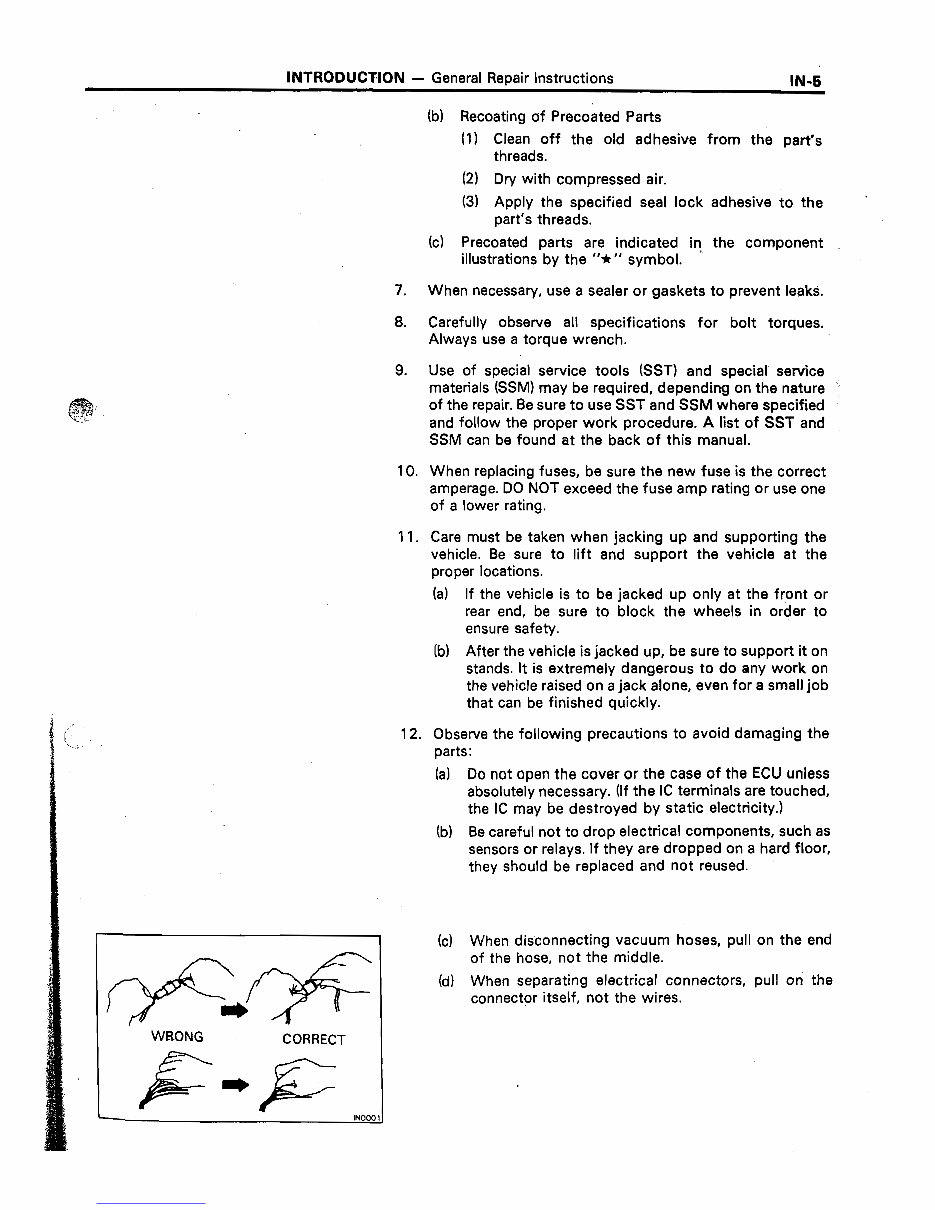
WRONG
CORRECT
12. Observe the following precautions to avoid damaging the
parts:
(a) Do not open the cover or the case of the ECU unless
absolutely necessary. (If the IC terminals are touched,
the IC may be destroyed by static electricity.)
(b) Be careful not to drop electrical components, such as
sensors or relays. If they are dropped on a hard floor,
they should be replaced and not reused.
(c) When disconnecting vacuum hoses, pull on the end
of the hose, not the middle.
(d) When separating electrical connectors, pull on the
connector itself, not the wires.
Downloaded from www.Manualslib.com manuals search engine
-.
EM-1
I
ENGINE MECHANICAL
../_ :.
F&e.
DESCRIPTION . . . ..1........111.......~....~.~ E+
TROUBLESHOOTING . . . . . . . . . . . . . . . . n . mam I. I. ”
ENGINE TUNE-UP . . . . . . . . . . . . ..~......~.......
COMPRESSION CHECK s e . . . . . . . . . . . . . , . . . . . . .
TIMING BELT ,,,..,....................*.*... EM-28
CYLINDER HEAD . . . . . . . . . . . . . . ..*............ EM-37
CYLINDER BLOCK
1”1......1...............,.. EM-66
Downloaded from www.Manualslib.com manuals search engine
EM-2
ENGINE MECHANICAL - Description
-.
DESCRl.PTlON _ .-. ..‘. /,. : --
+..>r:*. ,, .,. 2 ,-,. j . .:..,. .-
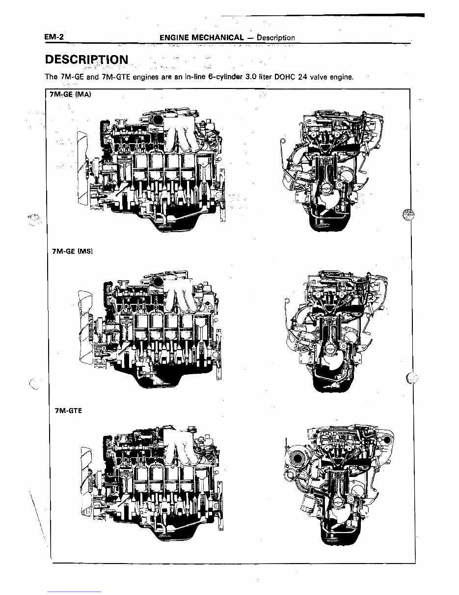
The 7M-GE and 7M-GTE engines are an in-line 6-cylinder 3.0 titer DOHC 24 valve engine.
i
‘M:G.E. (MA) ..
: _
7M-GE (MS)
7M-GTE
Downloaded from www.Manualslib.com manuals search engine
ENGINE MECHANICAL -, Description
EM-3
The 7M-GE, 7M-GTE engines are an in-line 6-
cylinder engine with the cylinders numbered l-2-
3-4-5-6 from the front. The crankshaft is sup-
ported by 7 bearings specified by the inside of the
crankcase. These bearings are made of kelmet.
.The crankshaft is integrated with 8 weights
which are cast along with it for balancing. Oil holes
‘are built into the crankshaft for supplying oil to the
connecting rods, pistons and other components.
These ignition order is l-5-3-6-2-4 .
The cylinder head is made of aluminum alloy, with
a cross flow type intake and exhaust layout and
with pent roof type combustion chambers. The
spark plugs are located in the center of the com-
bustion chambers.
Exhaust and intake valves are equipped with
irregular pitch springs with symmetrical ends
made of oil tempered silicon chrome steel wire
which are capable of following the valves even at
,high engine speeds.
Both the exhaust side cam shaft and the. intake
side cam shaft are driven by a single timing belt.
The cam journal is supported at 7 places between
the valve lifters of each cylinder and on the
cylinder head of front end. Lubrication of the cam
journal and cam is accomplished by oil being sup-
plied through the oiler port in the center of the
camshaft.
Adjustment of the valve clearance is done by
means of an outer shim type system, in which
valve adjusting shims are located above the valve
lifters. This permits replacement of the shims
without removal of the camshafts.
The resin timing belt cover is made in 2 pieces.
Pistons are made of highly temperature-resis-
tant aluminum alloy, and depressions are built into
the piston head to prevent interference with
valves.
Piston pins are the full-floating type, with the
pins fastened to neither the piston boss nor the
connecting rods. Instead, snap rings are fitted on
both ends of the pins, preventing the pins from
falling out.
The No. 1 compression ring is made of stainless
steel and the No. 2 compression ring is made of
cast iron. The oil ring is made of a combination of
stainless steel. The outer diameter of each piston
ring is slightly larger than the diameter of the
piston and the flexibility of the rings allows them
to hug the cylinder walls when they are mounted
on the piston. Compression rings No. 1 and No. 2
work to prevent the leakage of gas from the
cylinder and the oil ring works to scrape oil off the
cylinder walls to prevent it from entering the com-
bustion chamber.
The cylinder block is made of cast iron. It has 6
cylinders which are approximately 1.6 times the
length of the piston stroke. The top of the cylin-
ders is closed off by the cylinder head and the
lower end of the cylinders becomes the crankcase,
in which the crankshaft is installed. In addition,- the
cylinder block contains a water jacket, through
which coolant is pumped to cool the cylinders.
The .oil pan is bolted onto the botiom of the
cylinder block. The oil pan is an oil reservoir made .
of pressed steel sheet. A dividing included
-inside the oil pan to keep sufficient oil in the bot-
tom of the pan even when the vehicle is tilted. This
dividing plate also prevent5 the oil from making
waves when the vehicle is stopped suddenly and
thus shifting the oil away from the oil pump suc-
tion pipe.
Downloaded from www.Manualslib.com manuals search engine
You're Reading a Preview
What's Included?
Fast Download Speeds
Online & Offline Access
Access PDF Contents & Bookmarks
Full Search Facility
Print one or all pages of your manual
$28.99
Viewed 36 Times Today


Secure transaction
What's Included?
Fast Download Speeds
Online & Offline Access
Access PDF Contents & Bookmarks
Full Search Facility
Print one or all pages of your manual
$28.99
This is a comprehensive repair manual for the Toyota 7M-GE & 7M-GTE Engine.
- Format: .PDF
- Language: English
- Printable: Yes
- Compatibility: All Versions of Windows & Mac
- Requirements: Adobe Reader
Find it, print it, use it, then dispose of it. This manual contains numerous pictures and diagrams for easy reference.
All pages are printable, allowing you to have the necessary information with you at home, in the office, or at the repair shop. By performing your own repairs, you can save money. The manual provides easy-to-follow, step-by-step instructions suitable for any skill level.
Instant delivery means no shipping costs or waiting for a CD to arrive in the mail. Upon completion of payment via our secure payment processor, you will receive this manual today. We accept all major credit/debit cards and PayPal.


