

1984-1992 4.0L 3F & 3F-E Engine Service & Repair Manual
What's Included?
Fast Download Speeds
Offline Viewing
Access Contents & Bookmarks
Full Search Facility
Print one or all pages of your manual
TOYOTA.
REPAIR MANUAL
Dec.,1984
..
Pub .No .36253E
FOREWORD
This repair manual has been prepared to provide information
covering general service repairs for the 3F engine equipped on
the TOVOTA LAND CRUISER (Heavy-Duty).
Applicable models:
FJ62 , 70. 73 and 75 series
All information contained in this manual is the most up-to-date
at the time of publication. However, specifications and pro-
cedures are subject to change without notice.
TOYOTA MOTOR CORPORATION
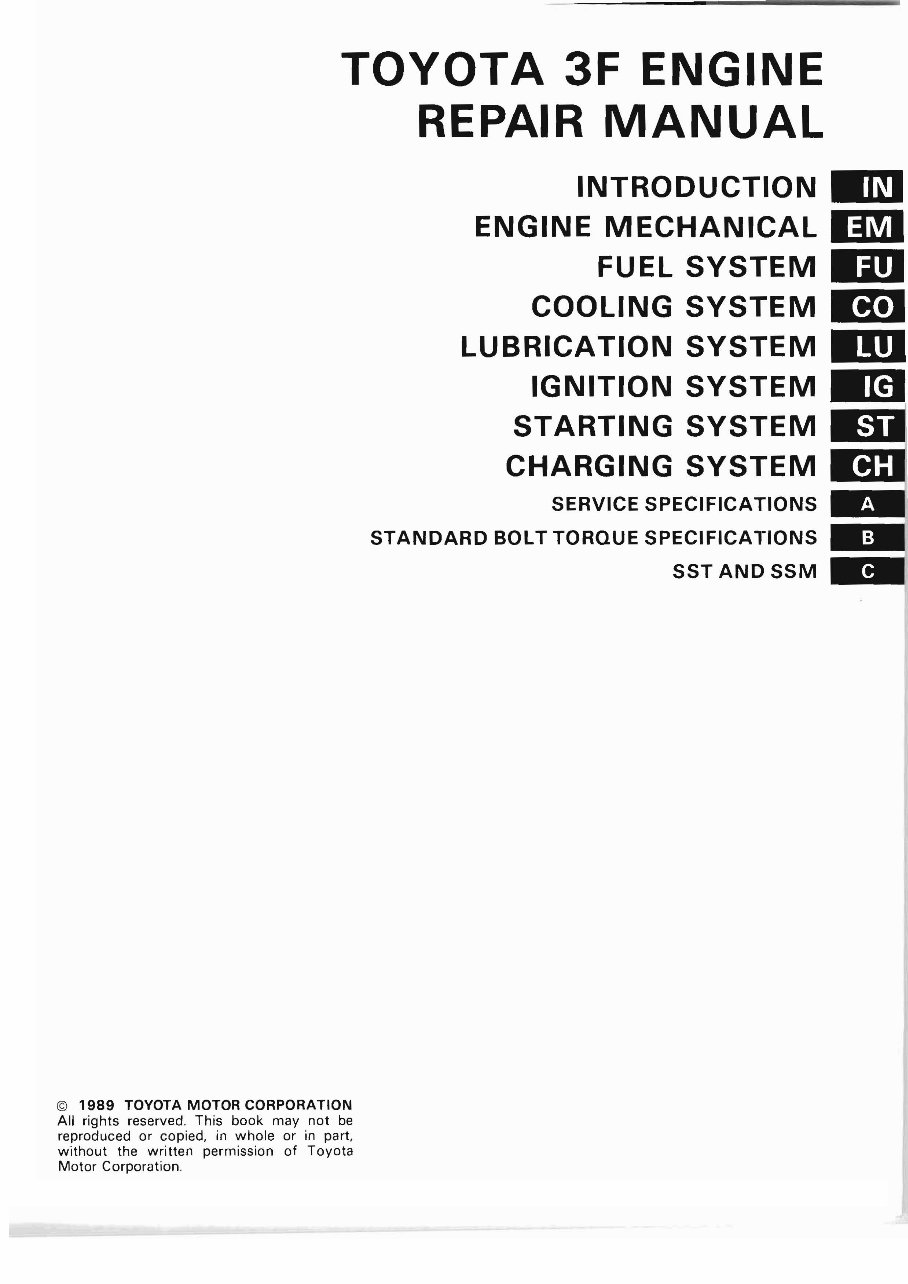
TOYOTA 3F ENGINE
REPAIR MANUAL
INTRODUCTION ED
ENGINE MECHANICAL 1m
FUEL SYSTEM liD
COOLING SYSTEM D!J
LUBRICATION SYSTEM 11m
IGNITION SYSTEM .a
STARTING SYSTEM EI
CHARGING SYSTEM ED
SERVICE SPECIFICATIONS ..
STANDARD BOLT TORQUE SPECIFICATIONS
SSTANDSSM ..
© 1989 TOYOTA MOTOR CORPORATION
All rights reserved. This book may not be
reproduced or copied, in whole or in part ,
without the written permission of Toyota
Motor Corporat ion .

IN-1
INTRODUCTION
HOW TO USE THIS MANUAL .
Page
IN-2
IDENTIFICATION INFORMATION .
ABBREVIATIONS USED IN THIS MANUAL . IN -7
IN-4
GENERAL REPAIR INSTRUCTIONS . IN-4
IN-2 INTRODUCTION - How to Use This Manual
HOW TO USE THIS MANUAL
To assist in finding your way through this manual. the section
title and major heading are given at the top of every page .
An INDEX is provided on the 1st page of each section to guide
you to the item to be repaired.
At the beginning of each section, PRECAUTIONS are given
that pertain to all repair operations contained in that section.
Read these precautions before starting any repair task.
TROUBLESHOOTING tables are included for each system to
help you diagnose the system problem and find the cause. The
repair for each possible cause is referenced in the remedy col-
umn to quickly lead you to the solution.
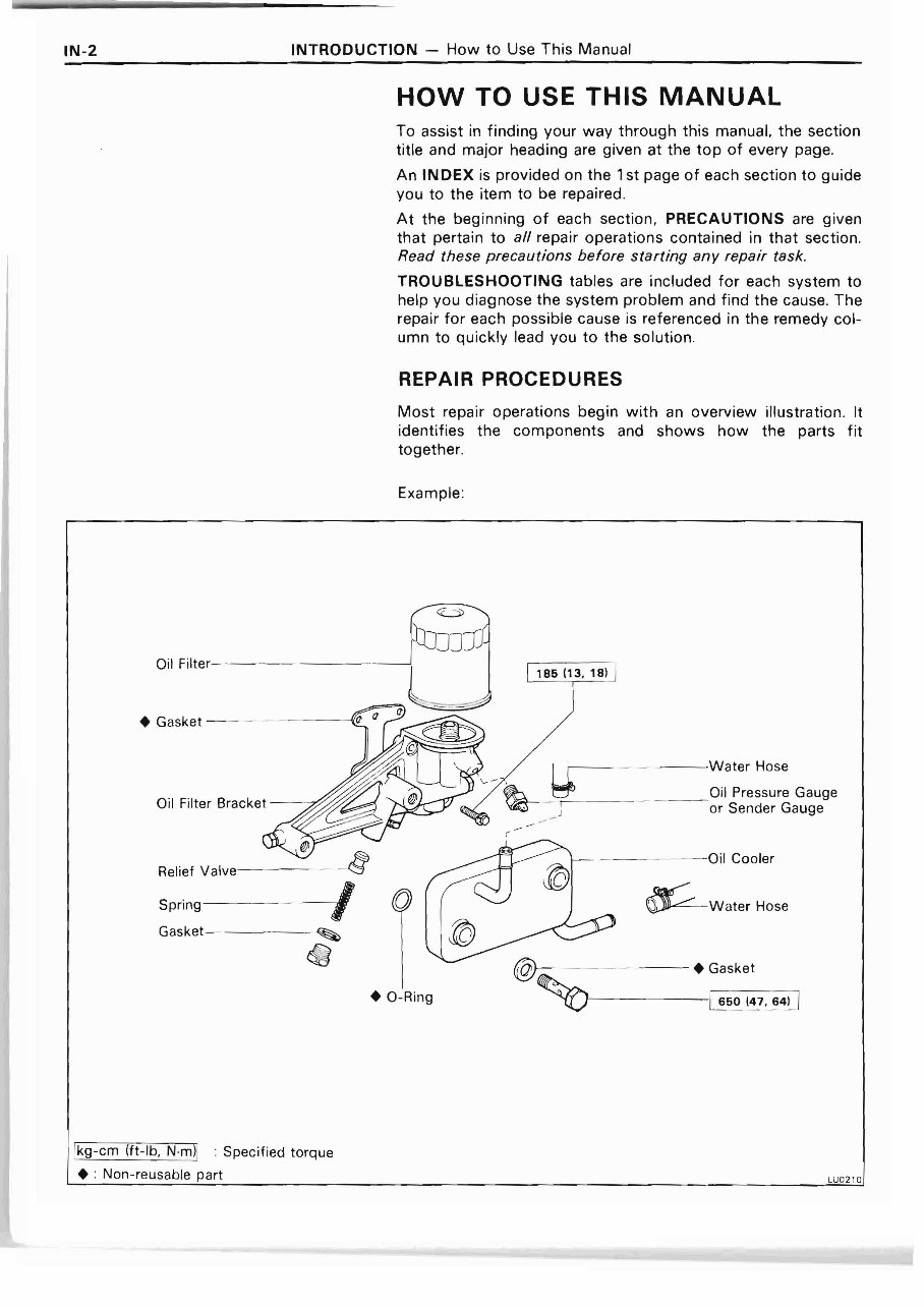
REPAIR PROCEDURES
Most repair operations begin with an overview illustration. It
identifies the components and shows how the parts fit
together .
Example :
Oil
• Gasket
I r-- - - - - - - W ater Hose
Oil Pressure Gauge
Oil Filter Bracket
_ J
I or Sender Gauge
r
\--- - - - - -O il Cooler
Relief valve - -- - - -' §
I Spring
Gasket
• a -Ring
'---- -- --- 1 650 147. 64) I
Ikg-cm 1ft-lb. N.mll : Specified torque
• : Non-reusable part
LU0 2,O
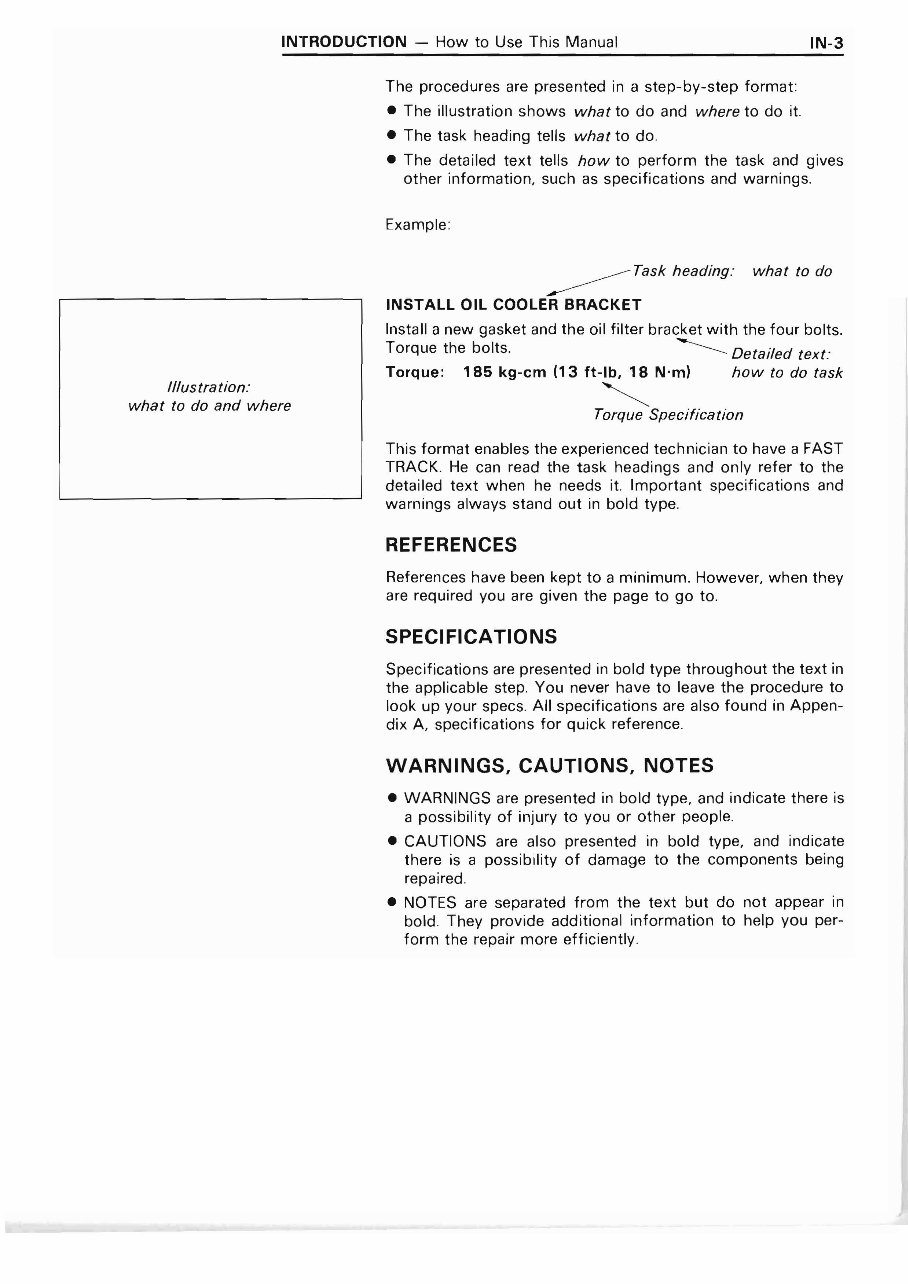
INTRODUCTION - How to Use This Manual IN-3
//Ius tra tion :
what to do and where
The procedures are presented in a step-by-step format:
• The illustration shows what to do and where to do it.
• The task heading tells what to do .
• The detailed text tells how to perform the task and gives
other information, such as specifications and warnings.
Example :
Task heading : what to do
INSTALL OIL COOLER BRACKET
Install a new gasket and the oil filter bracket with the four bolts.
Torque the bolts. --------- Detailed text :
Torque: 185 kg-em (13 ft-Ib, 18 N'm) how to do task
<.
Torque Specification
This format enables the experienced technician to have a FAST
TRACK . He can read the task headings and only refer to the
deta iled text when he needs it. Important spec ificat ions and
warnings always stand out in bold type .
REFERENCES
References have been kept to a minimum. However, when they
are required you are given the page to go to.
SPECIFICATIONS
Specifications are presented in bold type throughout the text in
the applicable step. You never have to leave the procedure to
look up your specs. All specifications are also found in Appen-
dix A, specifications for quick reference.
WARNINGS, CAUTIONS, NOTES
• WARNINGS are presented in bold type, and indicate there is
a possibility of injury to you or other people.
• CAUTIONS are also presented in bold type, and indicate
there is a possibility of damage to the components being
repaired.
• NOTES are separated from the text but do not appear in
bold. They provide additional information to help you per-
form the repair more efficiently.
IN-4 INTRODUCTION - Identification Information, General Repair Instructions
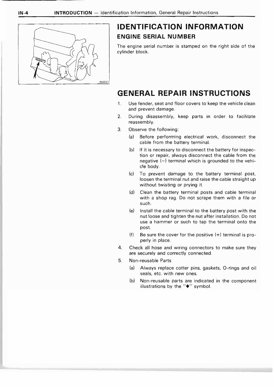
IDENTIFICATION INFORMATION
ENGINE SERIAL NUMBER
The engine serial number is stamped on the right side of the
cylinder block .
IN0 037
GENERAL REPAIR INSTRUCTIONS
1. Use fender, seat and floor covers to keep the vehicle clean
and prevent damage.
2. During disassembly, keep parts in order to facilitate
reassembly.
3. Observe the following :
(a) Before performing electrical work, disconnect the
cable from the battery terminal.
(b) If it is necessary to disconnect the battery for inspec-
tion or repair, always disconnect the cable from the
negative (-) terminal which is grounded to the vehi-
cle body .
(c) To prevent damage to the battery terminal post,
loosen the terminal nut and raise the cable straight up
without twisting or prying it.
(d) Clean the battery terminal posts and cable terminal
with a shop rag. Do not scrape them with a file or
such.
(e) Install the cable terminal to the battery post with the
nut loose and tighten the nut after installation. Do not
use a hammer or such to tap the terminal onto the
post.
(f) Be sure the cover for the positive (+) terminal is pro-
perly in place.
4. Check all hose and wiring connectors to make sure they
are securely and correctly connected.
5. Non-reusable Parts
(a) Always replace cotter pins, gaskets, a-rings and oil
seals, etc. with new ones.
(b) Non-reusable parts are indicated in the component
illustrations by the .. + .. symbol.
INTRODUCTION - General Repair Instructions
IN-5
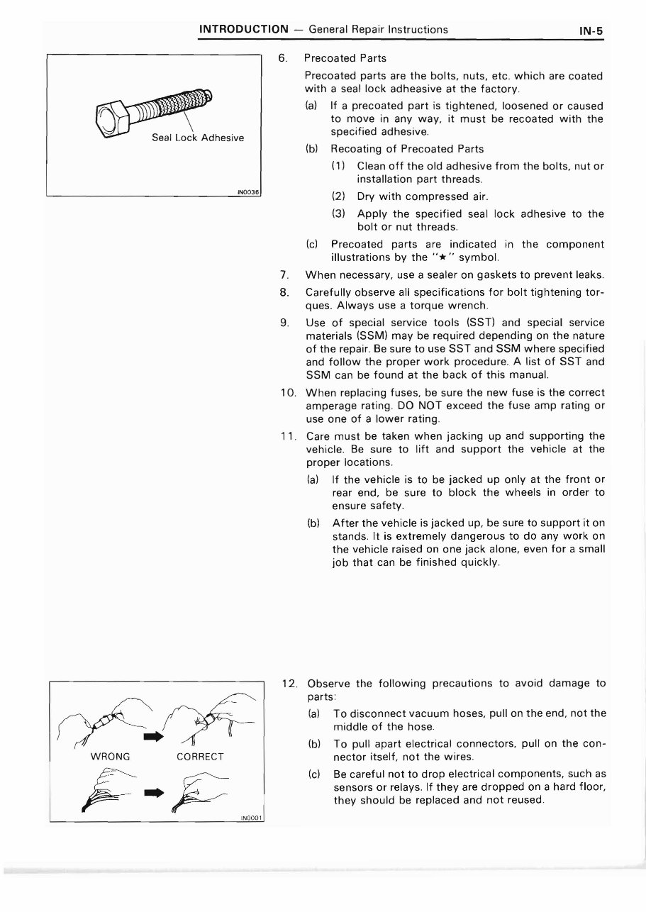
6. Precoated Parts
Precoated parts are the bolts. nuts, etc. which are coated
w ith a seal lock adheasive at the factory .
(a) If a precoated part is tightened . loosened or caused
to move in any way, it must be recoated with the
specified adhesive.
(b) Recoating of Precoated Parts
(1) Clean off the old adhesive from the bolts, nut or
installation part threads .
IN0 0 3 6
(2) Dry with compressed air.
(3) Apply the specified seal lock adhesive to the
bolt or nut threads .
(c) Precoated parts are indicated in the component
illustrations by the "* .. symbol.
7. When necessary, use a sealer on gaskets to prevent leaks.
8. Carefully observe all specifications for bolt tightening tor-
ques. Always use a torque wrench.
9. Use of special service tools (SST) and special service
materials (SSM) may be required depending on the nature
of the repa ir. Be sure to use SST and SSM where specified
and follow the proper work procedure . A list of SST and
SSM can be found at the back of th is manual.
10. When replacing fuses, be sure the new fuse is the correct
amperage rat ing. DO NOT exceed the fuse amp rat ing or
use one of a lower rating.
11 . Care must be taken when jacking up and supporting the
veh icle. Be sure to lift and support the veh icle at the
proper locations.
(a) If the vehicle is to be jacked up only at the front or
rear end. be sure to block the wheels in order to
ensure safety .
(b) After the veh icle is jacked up. be sure to support it on
stands. It is extremely dangerous to do any work on
the vehicle raised on one jack alone. even for a small
job that can be finished quickly .
WRONG CORRECT
IN000 1
12 . Observe the following precautions to avoid damage to
parts:
(a) To d isconnect vacuum hoses. pull on the end. not the
middle of the hose.
(b) To pull apart electr ical connectors, pull on the con-
nector itself. not the wires .
(c) Be careful not to drop electrical components, such as
sensors or relays. If they are dropped on a hard floor .
they should be replaced and not reused .
IN-6 INTRODUCTION - General Repair Instructions
(d) When steam cleaning an engine, protect the distribu-
tor , ignition coil, air filter, and VCV from water.
(e) Never use an impact wrench to remove or install ther-
mo switches or thermo sensors.
(f) When checking cont inu ity at the wire connector,
insert the tester probe carefully to prevent terminals
from bending.
(g) When using a vacuum gauge, never force the hose
onto a connector that is too large . Use a step-down
adapter instead. Once the hose has been stretched, it
may leak.
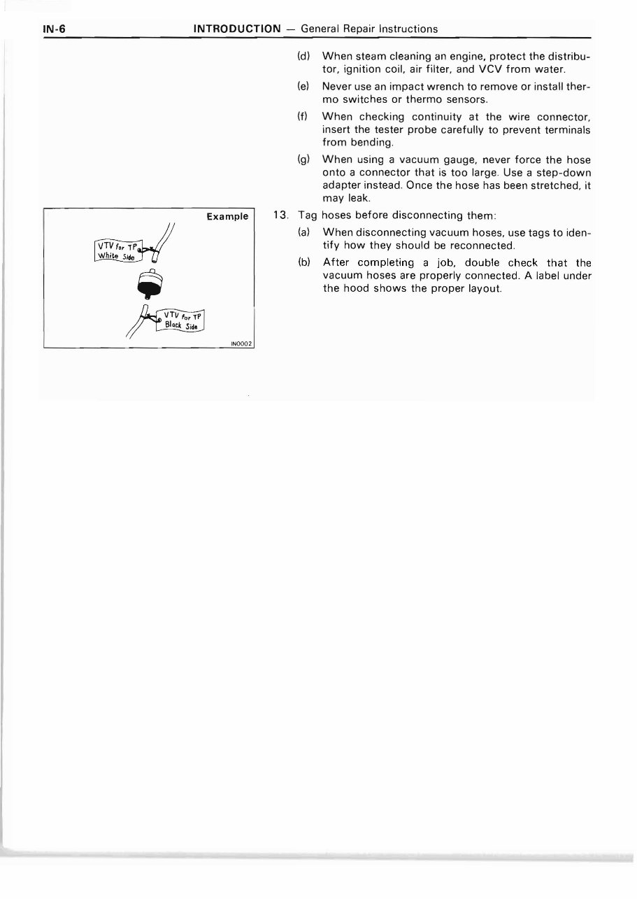
Example 13. Tag hoses before disconnecting them:
(a) When disconnecting vacuum hoses, use tags to iden-
t ify how they should be reconnected.
(b) After completing a job, double check that the
vacuum hoses are properly connected. A label under
the hood shows the proper layout.
IN000 2
You're Reading a Preview
What's Included?
Fast Download Speeds
Offline Viewing
Access Contents & Bookmarks
Full Search Facility
Print one or all pages of your manual
$39.99
Viewed 22 Times Today


Secure transaction
What's Included?
Fast Download Speeds
Offline Viewing
Access Contents & Bookmarks
Full Search Facility
Print one or all pages of your manual
$39.99
This workshop service repair manual covers the 4.0L 3F & 3F-E engines from 1984 to 1992. It includes the following:
- Introduction
- Tightening Torque
- Special Service Tools
- Maintenance Procedure
- Engine Mechanical
- Cylinderhead-Cylinder
- Crankcase-Crankshaft
- Piston & Connecting Rod
- Valve & Piston Pin
- Air Cleaner System
- Engine Fuel System
- Timing Gear & Camshaft
- Carburetor System
- Fuel Injection System
- Electronic Control System
- Fuel Pressure Regulator
- Cooling System
- Thermostat
- Intake System
- Exhaust System
- Lubrication System
- Ignition System
- Starting System
- System Circuit
- Charging System
- Alternator System
- Circuit Diagrams
- Service Specifications
This comprehensive manual provides detailed exploded views and step-by-step procedures with illustrations. It is suitable for both professional mechanics and DIY enthusiasts for repairs, maintenance, and servicing of the engines.


