Toyota 3.0L (2JZ-GE/2JZ-GTE) & 4.0L (1UZ-FE) Engines Service & Repair Manual
What's Included?
Lifetime Access
Fast Download Speeds
Offline Viewing
Access Contents & Bookmarks
Full Search Facility
Print one or all pages of your manual
CHARGING SYSTEM CH–1
DESCRIPTION CH00H–08 The generator is a small, high–rpm, high–performance type with an voltage regulator incorporated. The voltage regulator uses integrated circuits and controls the voltage produced by the generator. PRECAUTION CH00K–01 1. Check that the battery cables are connected to the correct terminals. 2. Disconnect the battery cables when the battery is given a quick charge. 3. Do not perform tests with a high voltage insulation resistance tester. 4. Never disconnect the battery while the engine is running. CH–2 – CHARGING SYSTEM PRECAUTION
DESCRIPTION CH00H–08 The generator is a small, high–rpm, high–performance type with an voltage regulator incorporated. The voltage regulator uses integrated circuits and controls the voltage produced by the generator. PRECAUTION CH00K–01 1. Check that the battery cables are connected to the correct terminals. 2. Disconnect the battery cables when the battery is given a quick charge. 3. Do not perform tests with a high voltage insulation resistance tester. 4. Never disconnect the battery while the engine is running. CH–2 – CHARGING SYSTEM PRECAUTION
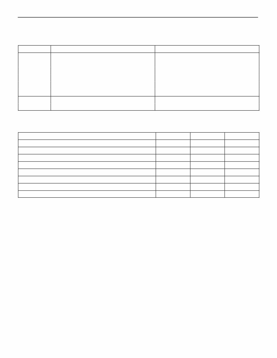
SERVICE SPECIFICATIONS CH01B–0A SERVICE DATA Battery Specific gravity (When full charge at 20°C (68°F)) 1.27–1.29 Generator Rated output 12 V–100 A Rotor coil resistance 2.8–3.0 W Slip ring diameter (STD) 14.2 mm–14.4 mm (0.559–0.567 in.) Slip ring diameter (Minimum) 12.8 mm (0.504 in.) Brush exposed length (STD) 10.5 mm (0.413 in.) Brush exposed length (Minimum) 1.5 mm (0.059 in.) Voltage Regulating voltage at 25°C (77°F) 13.7–14.7 V regulator Regulating voltage at 115°C (239°F) 13.2–14.0 V CH01D–09 TORQUE SPECIFICATIONS Part tightened N⋅m kgf⋅cm ft⋅lbf Rectifier end frame X Drive end frame 4.5 46 40 in.⋅lbf Generator pulley X Rotor 110 1,125 81 Rectifier X Rectifier end frame 2.9 30 26in.⋅lbf Bolt for plate terminal 3.8 39 34 in.⋅lbf Nut for terminal B 6.5 66 58 in.⋅lbf Generator cover X Generator 4.5 46 40 in.⋅lbf Generator X Generator bracket 37 380 27 Generator X Cylinder block 37 380 27 CH–24 – CHARGING SYSTEM SERVICE SPECIFICATIONS
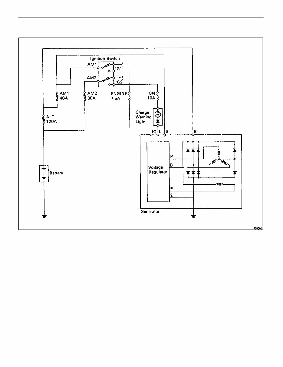
SYSTEM CIRCUIT CH00M–02 OPERATION CH00P–08 When the ignition switch is turned ON, current from the battery flows from terminal L of the generator through the voltage regulator to terminal E, causing the discharge warning light to light up. Then when the engine is started, the voltage output increases as the generator rpm increases. When the voltage output becomes greater than the battery voltage, current for recharging flows from terminal B. Simultaneously, voltage at terminal L increase and the potential difference between battery and terminal L disappears, causing the discharge warning light to go off. When the voltage output exceeds the regulator adjustment voltage, the transistor inside the voltage regulator regulates the voltage so that the voltage from the generator remains constant. – CHARGING SYSTEM OPERATION CH–3
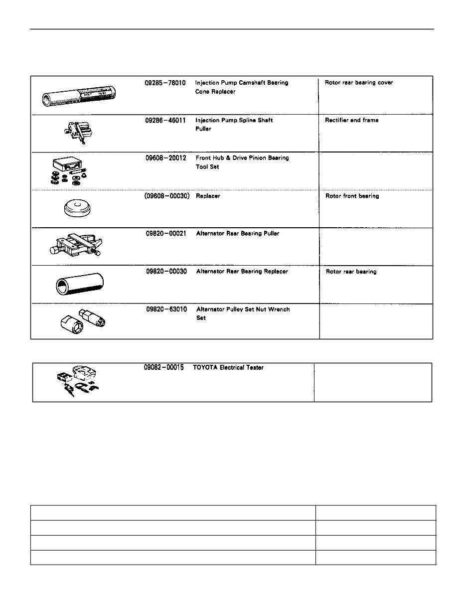
PREPARATION CH00R–01 SST (SPECIAL SERVICE TOOLS) CH00T–02 RECOMMENDED TOOLS CH00V–02 EQUIPMENT Ammeter(A) Battery specific gravity gauge Battery Torque wrench Vernier calipers Rotor (Slip ring) CH–4 – CHARGING SYSTEM PREPARATION
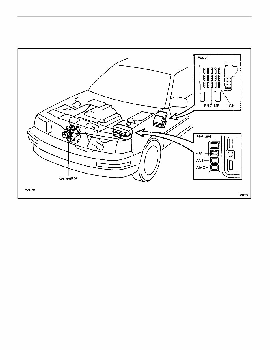
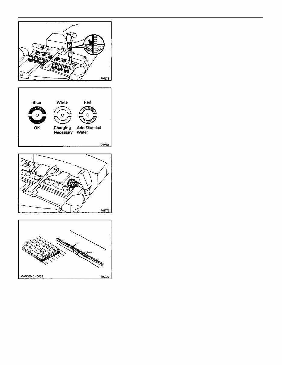
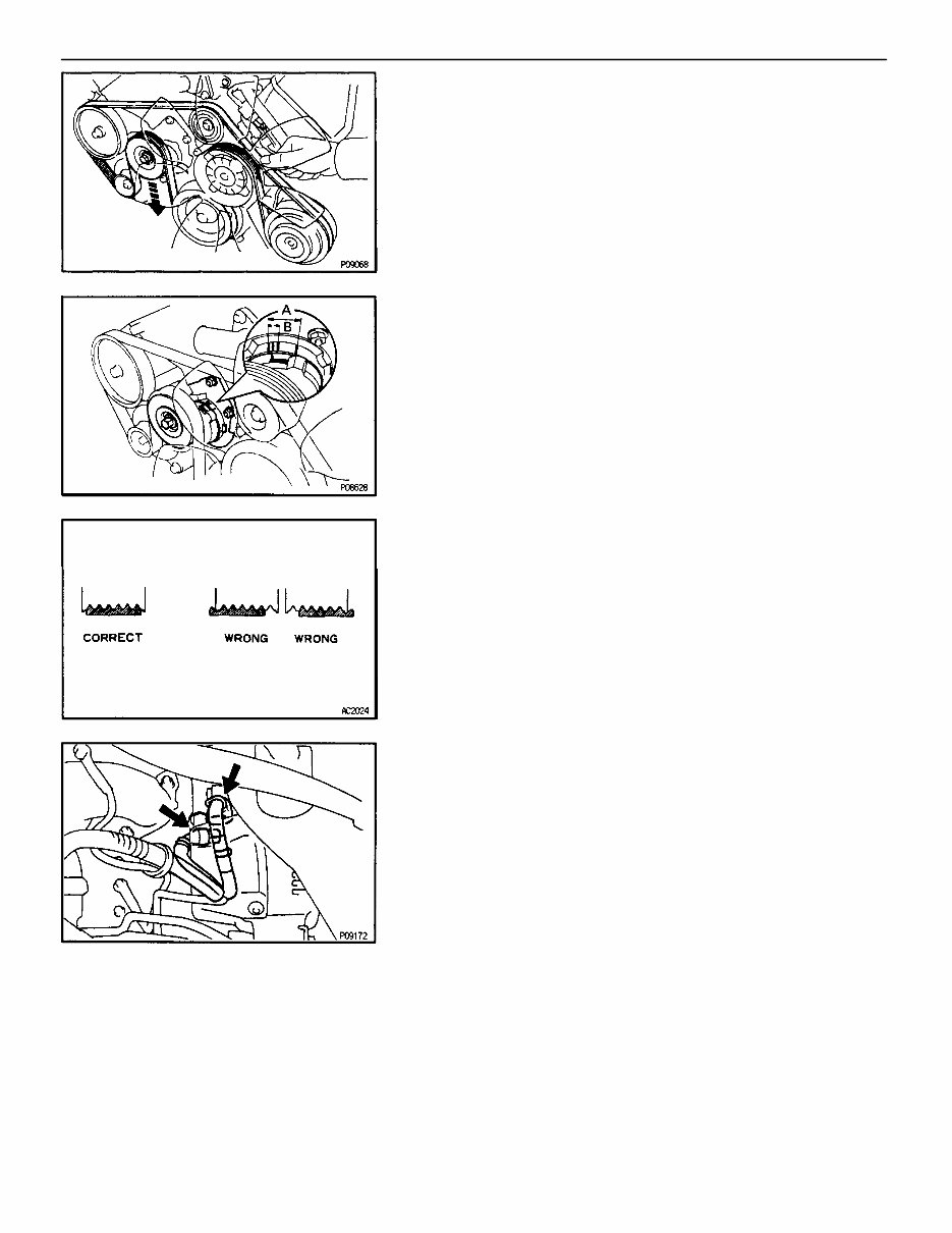
ON–VEHICLE INSPECTION CH03P–02 1. CHECK BATTERY SPECIFIC GRAVITY AND ELECTROYTE LEVEL (a) Check the electrolyte quantity of each cell. If insufficient, refill with distilled (or purified) water. (b) Check the specific gravity of each cell. Standard specific gravity: 1.27–1.29 at 20°C (68°F) If not within specifications, charge the battery. HINT: Check the indicator as shown. 2. CHECK BATTERY TERMINALS AND FUSES (a) Check that the battery terminals are not loose or corroded. (b) Check the fuses for continuity. H–Fuse: ALT 120A AM1 40A AM2 30A Fuse: ENG 7.5A IGN 10A 3. INSPECT DRIVE BELT HINT: A belt tensioner is used, so checking the belt tension is not necessary. (a) Visually check the drive belt for excessive wear, frayed cords etc. If necessary, replace the drive belt. HINT: • Cracks on the rib side of a drive belt are considered acceptable. If the drive belt has chunks missing from the ribs, it should be replaced. • The drive belt tension can be released by turning the belt tensioner counterclockwise. The pulley bolt for the belt tensioner has a left–hand thread. – CHARGING SYSTEM ON–VEHICLE INSPECTION CH–5
(b) Check the belt tensioner operation. • Check that the belt tensioner moves downward when the drive belt is pressed down at the points indicated in the illustration with approx. 98 N (10 kgf, 22.0 lbf) of force. • Check the alignment of the belt tensioner pulley to make sure the drive belt has not slipped off the pulley. If necessary, replace the belt tensioner. • Check that the arrow mark on the belt tensioner falls within area A of the scale. If it is outside area A, replace the drive belt. HINT: • When a new belt is installed, it should lie within area B. If not, the drive belt is not correct. • After installing a belt, check that it fits properly in the ribbed grooves. • Check by hand to confirm that the belt has not slipped out of the groove on the bottom of the pulley. 4. REMOVE ENGINE UNDER COVER 5. VISUALLY CHECK GENERATOR WIRING AND LISTEN FOR ABNORMAL NOISES (a) Check that the wiring is in good condition. (b) Check that there is no abnormal noise from the generator while the engine is running. 6. CHECK CHARGE WARNING LIGHT CIRCUIT (a) Warm up the engine and then turn it off. (b) Turn off all accessories. (c) Turn the ignition switch “ON”. Check that the charge warning light is lit. (d) Start the engine. Check that the light goes off. If the light does not go off as specified, troubleshoot the charge light circuit. CH–6 – CHARGING SYSTEM ON–VEHICLE INSPECTION
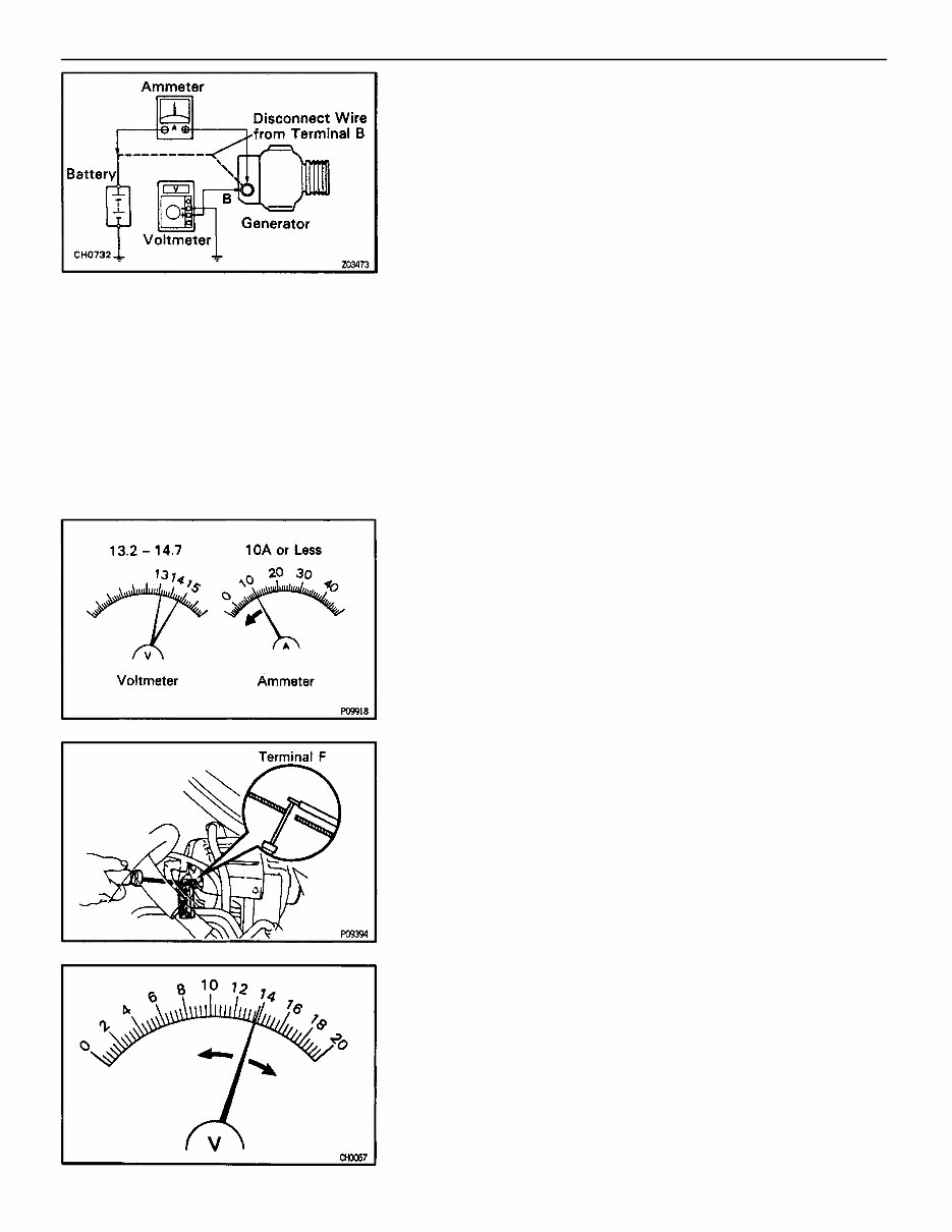
7. INSPECT CHARGING CIRCUIT WITHOUT LOAD HINT: If a battery/generator tester is available, connect the tester to the charging circuit as per manufacturer’s instruc- tions. (a) If a tester is not available, connect a voltmeter and ammeter to the charging circuit as follows: • Disconnect the wire from terminal B of the generator and connect it to the negative (–) probe of the ammeter. • Connect the positive (+) probe of the ammeter to terminal B of the generator. • Connect the positive (+) probe of the voltmeter to terminal B of the generator. • Ground the negative (–) probe of the voltmeter. (b) Check the charging circuit as follows: With the engine running from idling to 2,000 rpm, check the reading on the ammeter and voltmeter. Standard amperage: 10 A or less Standard voltage: 13.7–14.7 V at 25°C (77°F) 13.2–14.0 V at 115°C (239°F) If the voltmeter reading is more than standard voltage, re- place the voltage regulator. If the voltmeter reading is less than standard voltage, check the voltage regulator and generator as follows: • With terminal F grounded, start the engine and check the voltmeter reading of terminal B. • If the voltmeter reading is more than standard voltage, replace the voltage regulator. • If the voltmeter reading is less than standard voltage, check the generator. – CHARGING SYSTEM ON–VEHICLE INSPECTION CH–7
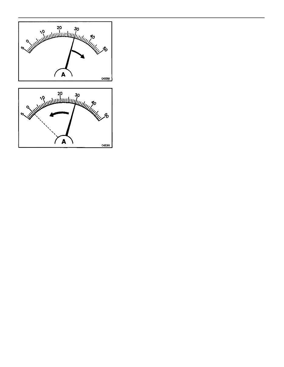
8. INSPECT CHARGING CIRCUIT WITH LOAD (a) With the engine running at 2,000 rpm, turn on the high beam headlights and place the heater blower switch at “HI”. (b) Check the reading on the ammeter. Standard amperage: 30 A or more If the ammeter reading is less than the standard amperage, repair the alternator. HINT: If the battery is fully charged, the indication will some- times be less than standard amperage. 9. REINSTALL ENGINE UNDER COVER CH–8 – CHARGING SYSTEM ON–VEHICLE INSPECTION
Discover the comprehensive workshop service repair manual tailored for the 3.0L 2JZ-GE, 2JZ-GTE, and 4.0L 1UZ-FE engines. This manual is a valuable resource for professional mechanics and DIY enthusiasts alike, offering easily accessible information.
It covers a range of engines, including the 3.0L 6-cylinder in-line, DOHC, 2JZ-GE engine, the 3.0L 6-cylinder in-line, turbocharged, DOHC, 2JZ-GTE engine, and the 4.0L 8-cylinder V-type, DOHC 1UZ-FE engine, providing comprehensive support.
Inside, you'll find detailed sections on:
Engine mechanical
Charging system
Cooling system
Emission control
Engine control system
Exhaust system
Fuel system
Ignition system
Intake system
Lubrication system
Starting system
Turbocharging
Troubleshooting
No aspect of engine maintenance and repair is left untouched in this manual.
It features detailed exploded views, step-by-step written procedures with accompanying pictures and diagrams, and the option to print selected pages or the entire manual, making it an essential tool for technicians and engine enthusiasts.
Whether you need to perform repairs, maintenance, or servicing on your engine, this manual will guide you through the process with precision and clarity, catering to both professional mechanics and DIY enthusiasts. Rest assured, you won't be disappointed with the wealth of information provided.
Elevate your engine repair capabilities with this exceptional workshop service repair manual for the 3.0L 2JZ-GTE and 4.0L 1UZ-FE engines. Acquire this invaluable resource today and experience the difference it makes.
Recently Viewed
5,521,897Happy Clients
2,594,462eManuals
1,120,453Trusted Sellers
15Years in Business
Price:
Actual Price:
Toyota 3.0L (2JZ-GE/2JZ-GTE) & 4.0L (1UZ-FE) Engines Service & Repair Manual