3.5L 2GR-FE and 2GR-FSE Engine Workshop Service Manual
What's Included?
Lifetime Access
Fast Download Speeds
Offline Viewing
Access Contents & Bookmarks
Full Search Facility
Print one or all pages of your manual
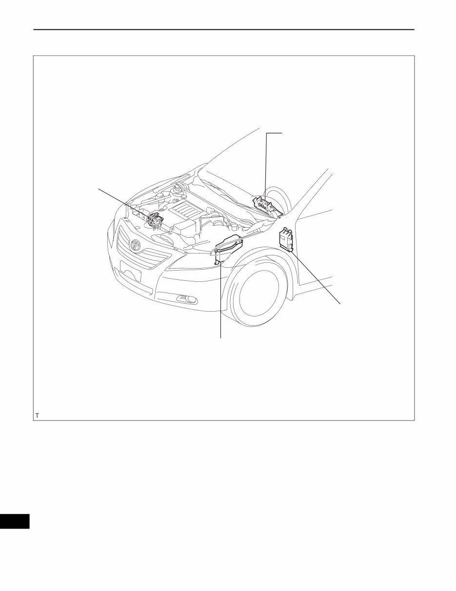
2GR-FE CHARGING – CHARGING SYSTEM CH–1 CH CHARGING SYSTEM PRECAUTION 1. Check that the battery cables are connected to the correct terminals. 2. Disconnect the battery cables when the battery is given a quick charge. 3. Do not perform tests with a high voltage insulation resistance tester. 4. Never disconnect the battery while the engine is running. 5. Check that the charging cable nut is tightened on terminal B of the generator and the engine room R/B.
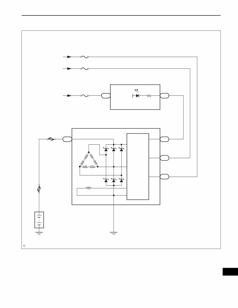
2GR-FE CHARGING – CHARGING SYSTEM CH–3 CH SYSTEM DIAGRAM From Battery From IG1 Relay From IG2 Relay ALT-S GAUGE No. 1 GAUGE No. 2 F1 13 IG+ IG+ Charge CHG- F1 23 Combination Meter IC Regulator C18 C18 C18 4 2 1 S IG L Generator C19 1 B ALT FL MAIN Battery A138773E01
CH–4 2GR-FE CHARGING – CHARGING SYSTEM CH PROBLEM SYMPTOMS TABLE Result Symptom Suspected area See page Charge Warning Light Comes ON while Driving 1. Clutch pulley CH-7 2. Generator assembly Noise Occurs from Generator while Engine is Running 1. V-ribbed belt CH-8 2. Clutch pulley 3. Generator assembly
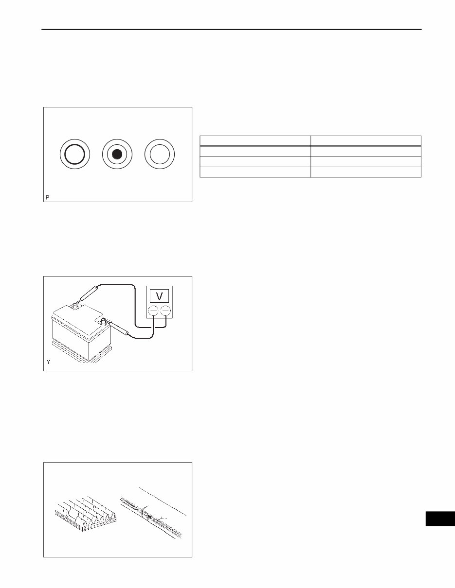
2GR-FE CHARGING – CHARGING SYSTEM CH–5 CH ON-VEHICLE INSPECTION 1. CHECK BATTERY ELECTROLYTE LEVEL (a) Check the electrolyte level. (1) If the electrolyte level is low, replace the battery (or add distilled water) and check the charging system. 2. CHECK BATTERY SPECIFIC GRAVITY (a) Check the color of the indicator. Result 3. CHECK BATTERY VOLTAGE (a) If it has not been 20 minutes since you drove the vehicle or since the engine was stopped, turn the ignition switch on (IG) and turn on the electrical systems (headlight, blower motor, rear defogger, etc.) for 60 seconds. This will remove the surface charge from the battery. (b) Turn off the ignition switch and the electrical systems. (c) Measure the battery voltage between the negative (- ) and positive (+) terminals of the battery. Standard voltage: 12.5 to 12.9 V at 20°C (68°F) HINT: If the voltage is below the specification, charge the battery. 4. CHECK BATTERY TERMINAL (a) Check that the battery terminals are not loose or corroded. If the terminals are corroded, clean them. 5. CHECK FUSES (a) Measure the resistance of the ALT fuse, ALT-S fuse, GAUGE No. 1 fuse and GAUGE No. 2 fuse. Standard resistance: Below 1 Ω If the result is not as specified, replace the fuses as necessary. 6. CHECK V-RIBBED BELT (a) Check the belt for wear, cracks or other signs of damage. If any of the following defects is found, replace the V-ribbed belt. • The belt is worn out, cracked, or the cords are exposed. • The cracks reach the cords in more than one place. • The belt has chunks missing from the ribs. Green Dark Clear or Light Yellow A115815E01 Indicator color Condition Green Good Dark Charging necessary Clear or light yellow Replacement necessary A081052E01 B000543
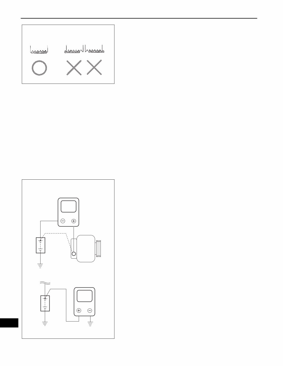
CH–6 2GR-FE CHARGING – CHARGING SYSTEM CH (b) Check that the belt fits properly in the ribbed grooves. HINT: Check with your hand to confirm that the belt has not slipped out of the groove on the bottom of the pulley. If it has slipped out, replace the V-ribbed belt. Install a new V-ribbed belt correctly. 7. VISUALLY CHECK GENERATOR WIRING (a) Check that the generator wiring is in good condition. If the condition is not good, repair or replace the generator wire. 8. LISTEN FOR ABNORMAL NOISES FROM GENERATOR (a) Check that there is no abnormal noise from the generator while the engine is running. If there is abnormal noise, replace the pulley or generator. 9. CHECK CHARGE WARNING LIGHT CIRCUIT (a) Turn the ignition switch on (IG). Check that the charge warning light comes on. (b) Start the engine and check that the light goes off. If the light does not operate as specified, troubleshoot the charge warning light circuit. 10. CHECK CHARGING CIRCUIT WITHOUT LOAD (a) According to the following procedure, connect an ammeter and voltmeter as shown in the illustration. (1) Disconnect the wire from terminal B of the generator and connect it to the negative (-) lead of the ammeter. (2) Connect the positive (+) lead of the ammeter to terminal B of the generator. (3) Connect the positive (+) lead of the voltmeter to positive (+) terminal of the battery. (4) Ground the negative (-) lead of the voltmeter. (b) Check the charging circuit. (1) While keeping the engine speed at 2,000 rpm, check the readings on the ammeter and voltmeter. Standard amperage: 10 A or less Standard voltage: 13.2 to 14.8 V If the results are not as specified, replace the generator assembly. HINT: • If the battery is not fully charged, the ammeter reading may be more than the standard amperage. In this case, increase electrical load by operating devices such as the wiper motor and rear window defogger. Then, recheck the reading on the ammeter. CORRECT INCORRECT B000540E03 V A Disconnect Wire from Terminal B Ammeter Battery Battery Generator Voltmeter A110265E04
2GR-FE CHARGING – CHARGING SYSTEM CH–7 CH 11. CHECK CHARGING CIRCUIT WITH LOAD (a) Keep the engine speed at 2,000 rpm, turn on the high beam headlights, and turn the heater blower switch to the "HI" position. (b) Check the reading on the ammeter. Standard amperage: 30 A or more If the ammeter reading is less than the standard amperage, replace the generator assembly. HINT: • If the battery is fully charged, the ammeter reading may be less than the standard amperage. In this case, increase electrical load by operating devices such as the wiper motor and rear window defogger. Then, recheck the reading on the ammeter.
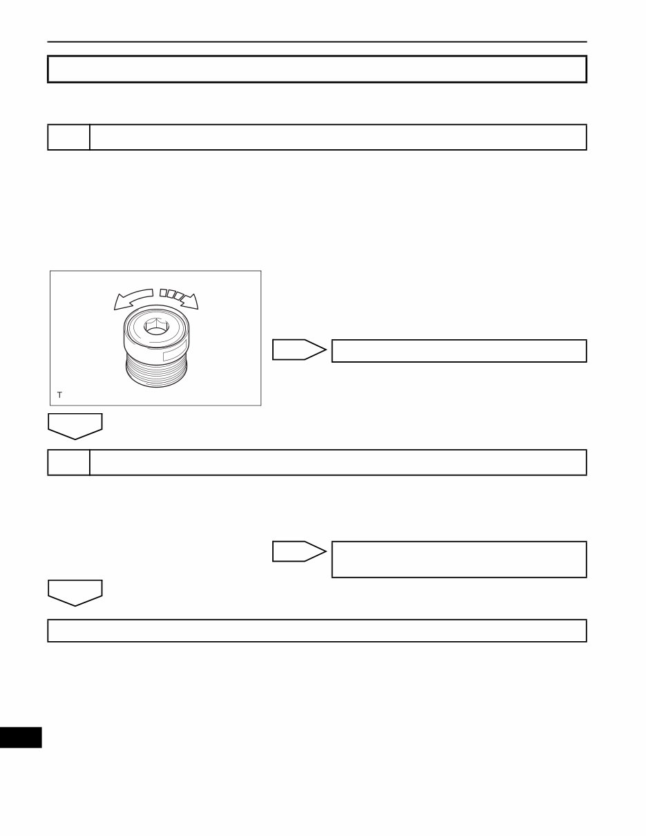
CH–8 2GR-FE CHARGING – CHARGING SYSTEM CH INSPECTION PROCEDURE (a) Check the lock function with the pulley installed in the vehicle. (1) Visually check that the rotor in the generator operates with the engine started. (b) Check the lock function with the pulley removed from the vehicle. (1) Remove the generator pulley cap. Using SST, hold the generator rotor. (2) Turn the clutch pulley clockwise and check that the outer ring locks. OK: The outer ring locks. SST 09820-63020 NG OK (a) Start the engine and visually check looseness of the clutch pulley. OK: The clutch pulley is not loose. NG OK Charge Warning Light Comes ON while Driving 1 CHECK LOCK FUNCTION OF CLUTCH PULLEY Free Lock A128078E01 REPLACE CLUTCH PULLEY 2 CHECK LOCK OF CLUTCH PULLEY TIGHTEN CLUTCH PULLEY TO THE SPECIFIED TORQUE REPLACE GENERATOR ASSEMBLY
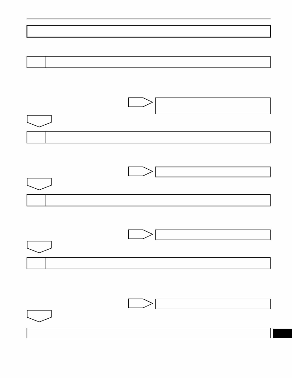
2GR-FE CHARGING – CHARGING SYSTEM CH–9 CH INSPECTION PROCEDURE (a) Check the tension of the belt by pushing it down with a finger. OK: The tension of the belt is enough. NG OK (a) Check the V-ribbed belt for wear. OK: The V-ribbed belt is not worn. NG OK (a) Check the clutch pulley groove for wear or other defects. OK: The clutch pulley groove is not damaged. NG OK (a) Perform a driving test and check if noise occurs when decelerating. OK: Noise does not occur. NG OK Noise Occurs from Generator while Engine is Running 1 CHECK LOOSENESS OF V-RIBBED BELT REPLACE V-RIBBED BELT TENSIONER ASSEMBLY 2 CHECK V-RIBBED BELT FOR WEAR REPLACE V-RIBBED BELT 3 CHECK CLUTCH PULLEY FOR WEAR REPLACE CLUTCH PULLEY 4 CHECK FOR NOISE WHILE CLUTCH PULLEY IS OPERATING REPLACE CLUTCH PULLEY REPLACE GENERATOR ASSEMBLY
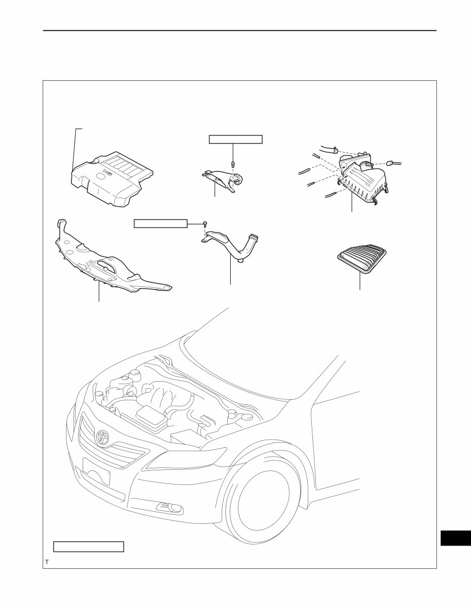
2GR-FE CHARGING – GENERATOR CH–9 CH ENGINE 2GR-FE CHARGING GENERATOR COMPONENTS NO. 1 AIR CLEANER INLET COOL AIR INTAKE DUCT SEAL V-BANK COVER SUB-ASSEMBLY 5.0 (51, 44 in.*lbf) 5.0 (51, 44 in.*lbf) N*m (kgf*cm, ft.*lbf) : Specified torque x2 AIR CLEANER FILTER ELEMENT AIR CLEANER CAP SUB-ASSEMBLY AIR CLEANER INLET ASSEMBLY A134975E01
Discover the 3.5L 2GR-FE and 2GR-FSE Engine Workshop Service Repair Manual, tailored for the 6-cylinder V-type engines. This manual offers a wealth of information on engine maintenance and repair, featuring detailed explanations, exploded views, pictures, and diagrams for easy comprehension. Whether you're a professional technician or a hands-on enthusiast, this manual is an essential resource for engine fixes.
Explore a wide range of topics, including engine mechanical, charging system, cooling system, emission control, engine control system, exhaust system, fuel system, ignition system, intake system, lubrication system, and starting system. Each section provides step-by-step procedures, empowering you to confidently perform repairs, maintenance, and servicing.
This manual is not only informative but also highly practical. You can print selected pages or the entire manual for convenient reference during your engine work. With detailed illustrations and comprehensive instructions, this manual is designed to meet your expectations.
Don't miss out on this invaluable resource for your 3.5L 2GR-FE and 2GR-FSE engines. Acquire the manual that professionals rely on to ensure the optimal performance of your engines.
Recently Viewed
5,521,897Happy Clients
2,594,462eManuals
1,120,453Trusted Sellers
15Years in Business
Price:
Actual Price:
3.5L 2GR-FE and 2GR-FSE Engine Workshop Service Manual