
 Engine Workshop Service Repair Manual")
Toyota 1.8L1ZZ-FED (ZZW30) Engine Service & Repair Manual
What's Included?
Fast Download Speeds
Offline Viewing
Access Contents & Bookmarks
Full Search Facility
Print one or all pages of your manual

CH021–01
– CHARGING CHARGING SYSTEM
CH–1
778 AuthorĂ: DateĂ:
2000 MR2 (RM760U)
CHARGING SYSTEM
PRECAUTION
S Check that the battery cables are connected to the correct terminals.
S Disconnect the battery cables when the battery is given a quick charge.
S Do not perform tests with a high voltage insulation resistance tester.
S Never disconnect the battery while the engine is running.
CH0DG–01
Z11577
Except Maintenance–Free Battery
Z11556
Voltmeter
Maintenance–Free Battery
Z11580
White Red
OK
Blue
Insufficient
Water
Charging
Necessary
CH–2
– CHARGING CHARGING SYSTEM
779 AuthorĂ: DateĂ:
2000 MR2 (RM760U)
ON–VEHICLE INSPECTION
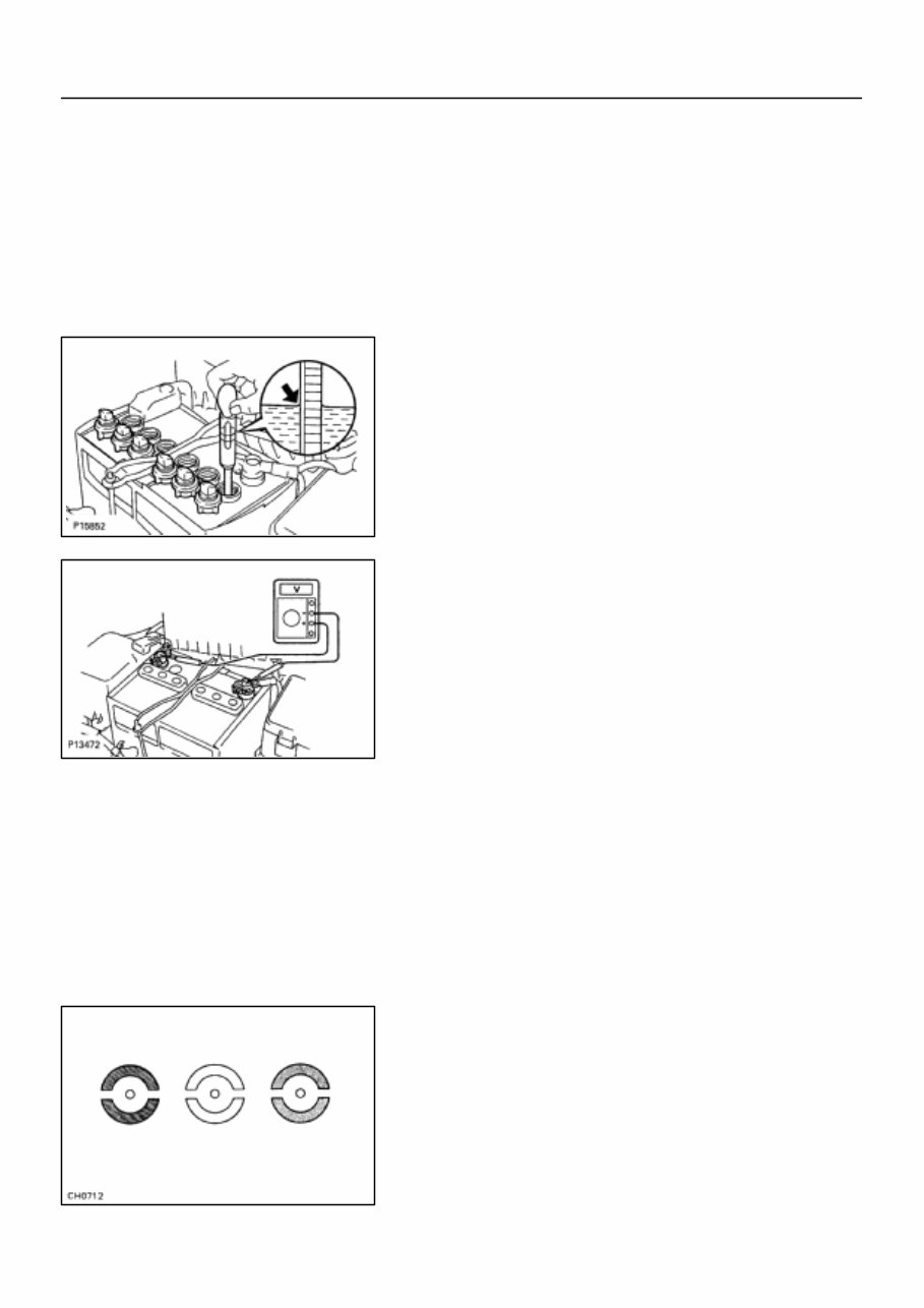
1. CHECK BATTERY ELECTROLYTE LEVEL
Check the electrolyte quantity of each cell.
Maintenance–Free Battery:
If under the lower level, replace the battery (or add distilled wa-
ter if possible) and check the charging system.
Except Maintenance–Free Battery:
If under the lower level, add distilled water.
2. Except Maintenance–Free Battery:
CHECK BATTERY SPECIFIC GRAVITY
Check the specific gravity of each cell.
Standard specific gravity: 1.25 – 1.29 at 20°C (68 °F)
If the specific gravity is less than specification, charge the bat-
tery.
3. Maintenance–Free Battery:
CHECK BATTERY VOLTAGE
(a) After having driven the vehicle and in the case that 20
minutes have not passed after having stopped the en-
gine, turn the ignition switch ON and turn on the electrical
system (headlight, blower motor, rear defogger etc.) for
60 seconds to remove the surface charge.
(b) Turn the ignition switch OFF and turn off the electrical sys-
tems.
(c) Measure the battery voltage between the negative (–)
and positive (+) terminals of the battery.
Standard voltage: 12.5 – 12.9 V at 20°C (68°F)
If the voltage is less than specification, charge the battery.
HINT:
Check the indicator as shown in illustration.
4. CHECK BATTERY TERMINALS, FUSIBLE LINK AND
FUSES
(a) Check that the battery terminals are not loose or cor-
roded.
(b) Check the fusible link, H–fuses and fuses for continuity.
B00543
B00145
B00146
B00540
CORRECT WRONG WRONG
– CHARGING CHARGING SYSTEM
CH–3
780 AuthorĂ: DateĂ:
2000 MR2 (RM760U)
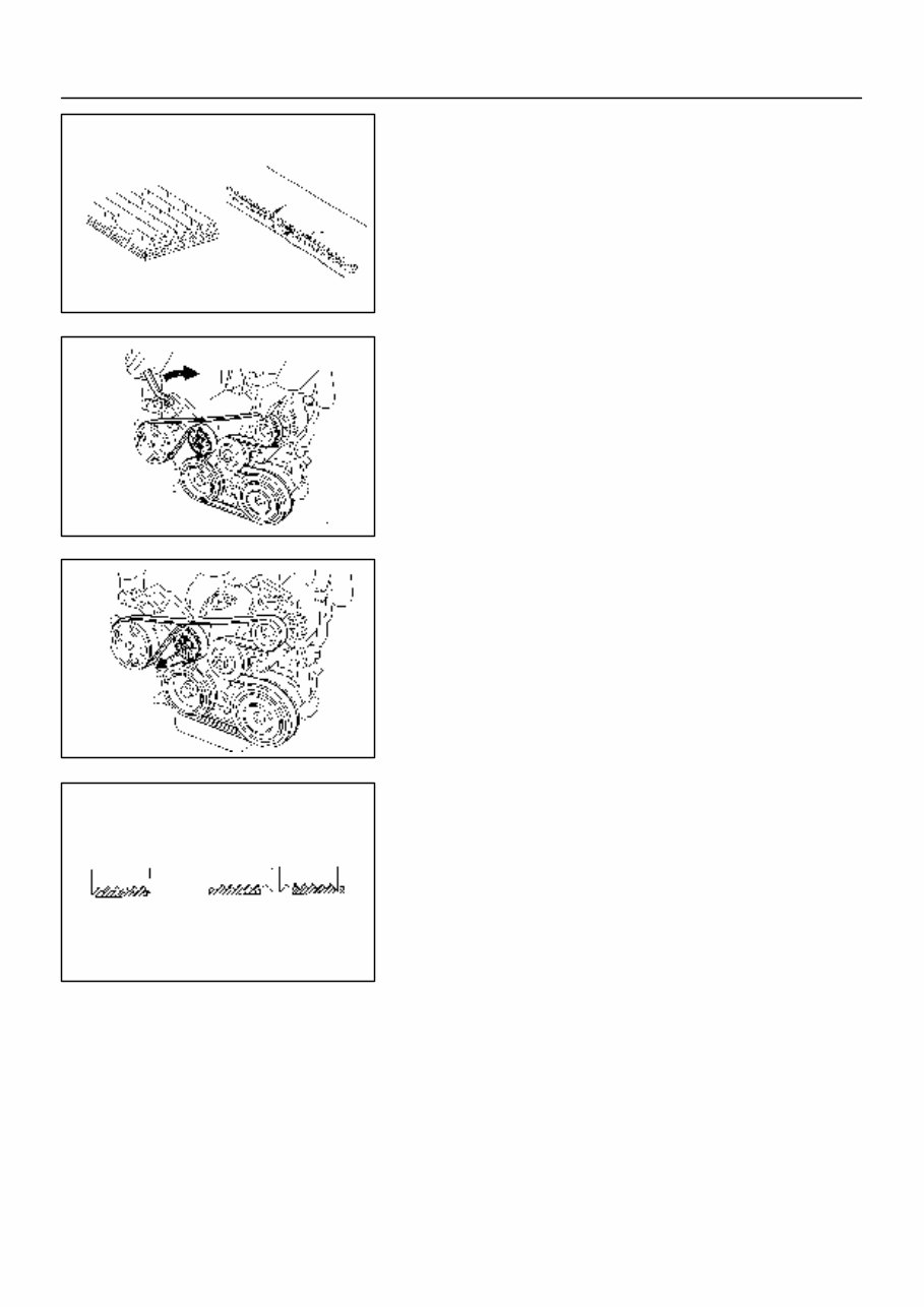
5. INSPECT DRIVE BELT
(a) Visually check the belt for excessive wear, frayed cords
etc.
If any defect has been found, replace the drive belt.
HINT:
Cracks on the rib side of a belt are considered acceptable.
If the belt has chunks missing from the ribs, it should be re-
placed.
HINT:
The drive belt tension can be released by turning the belt ten-
sioner clockwise.
(b) Check the belt tensioner operation.
S Check that belt tensioner moves downward when
the drive belt is pressed down at the points indi-
cated in the illustration with approx. 98 N (10 kgf,
22.0 lbf) of force.
S Check the alighment of the belt tensioner pulley to
make sure the drive belt will not slip off the pulley.
If necessary, replace the belt tensioner.
HINT:
S After installing a belt, check that it fits properly in the
ribbed grooves.
S Check with your hand to confirm that the belt has not
slipped out of the groove on the bottom of the pulley.
S After installing a new belts, run the engine for about 5 min-
utes and check the belt tension existing.
6. VISUALLY CHECK GENERATOR WIRING AND LIS-
TEN FOR ABNORMAL NOISES
(a) Check that the wiring is in good condition.
(b) Check that there is no abnormal noise from the generator
while the engine is running.
7. INSPECT DISCHARGE WARNING LIGHT CIRCUIT
(a) Turn the ignition switch ”ON”. Check that the discharge
warning light comes on.
(b) Start the engine. Check that the light goes off.
If the light does not operate as specified, troubleshoot the dis-
charge warning light circuit.
CH0732
Disconnect Wire
from Terminal B
Generator
Voltmeter
Battery
Ammeter
B09163
Terminal F
CH–4
– CHARGING CHARGING SYSTEM
781 AuthorĂ: DateĂ:
2000 MR2 (RM760U)
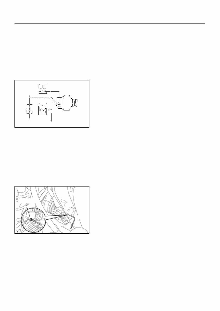
8. INSPECT CHARGING CIRCUIT WITHOUT LOAD
HINT:
If a battery/generator tester is available, connect the tester to
the charging circuit as permanufacturer’s instructions.
(a) If a tester is not available, connect a voltmeter to the
charging circuit as follows:
S Disconnect to the wire from terminal B of the gener-
ator and connect it to the negative (–) lead of the
ammeter.
S Connect the positive (+) lead of the ammeter to ter-
minal B of the generator.
S Connect the positive (+) lead of the voltmeter to ter-
minal B of the generator.
S Ground the negative (–) lead of the voltmeter.
(b) Check the charging circuit as follows:
With the engine running from idle to 2,000 rpm, check the
reading on the ammeter and voltmeter.
Standard amperage: 10A or less
Standard voltage: 13.2 – 14.0 V
If the voltmeter reading is more than standard voltage, replace
the voltage regulator.
If the voltmeter reading is less than the standard voltage, check
the voltage regulator and generator as follows:
S With terminal F grounded, start the engine and
check the voltmeter reading of terminal B.
S If the voltmeter reading is more than standard volt-
age, replace the voltage regulator.
S If the voltmeter reading is less than standard volt-
age, check the generator.
9. INSPECT CHARGING CIRCUIT WITH LOAD
(a) With the engine running at 2,000 rpm, turn on the high
beam headlights and place the heater blower switch at
”H”.
(b) Check the reading on the ammeter.
Standard amperage: 30 A or more
If the ammeter reading is less than standard amperage, repair
the generator.
HINT:
If the battery is fully charged, the indication will sometimes be
less than standard amperage.
CH023–04
B10240
Generator
Generator Connector
Generator Wire
Wire
Clamp
25 (255, 18)
54 (550, 40)
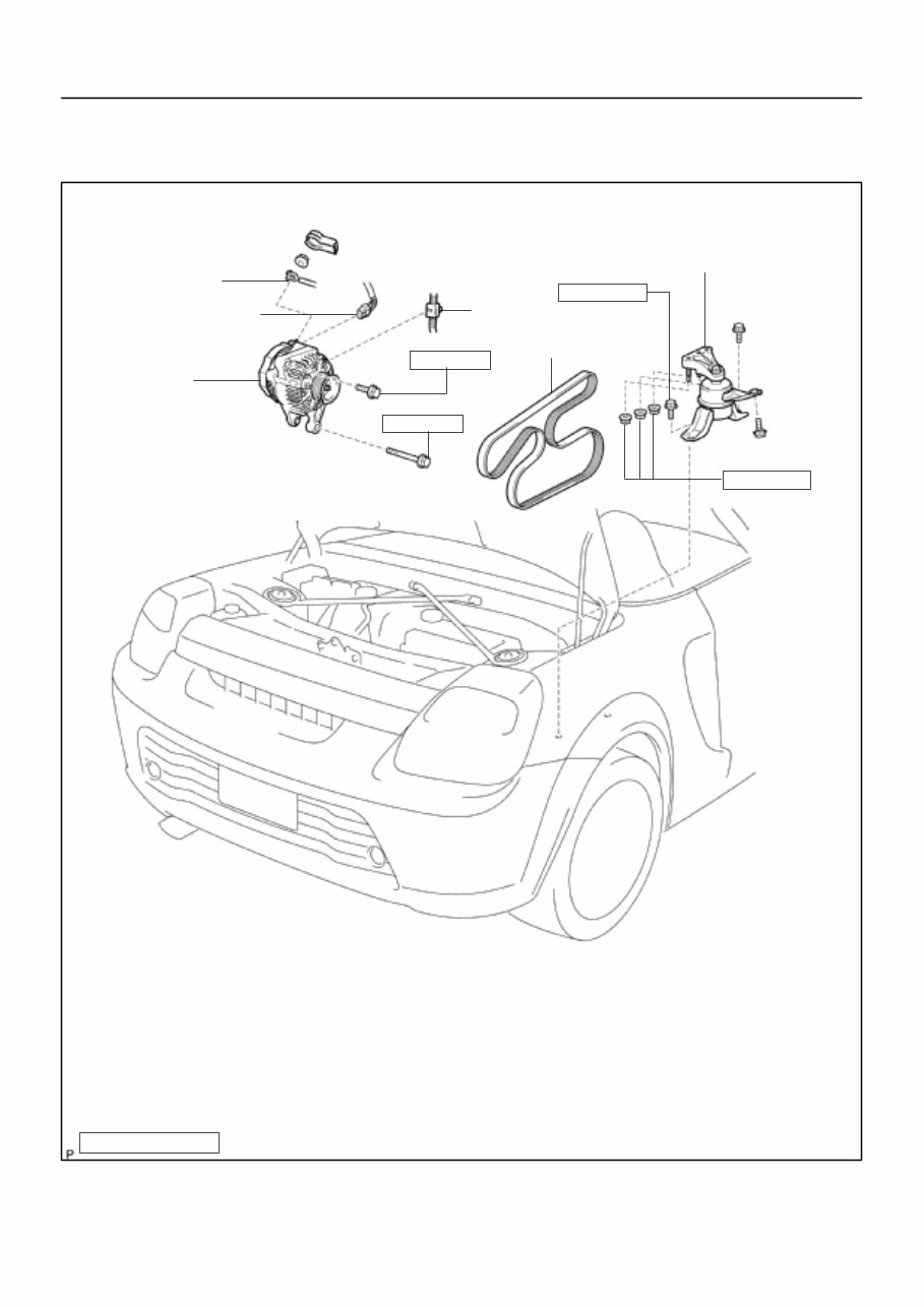
Drive Belt
52 (530, 38)
52 (530, 38)
RH Engine
Mounting Insulator
N·m (kgf·cm, ft·lbf)
: Specified torque
– CHARGING GENERATOR
CH–5
782 AuthorĂ: DateĂ:
2000 MR2 (RM760U)
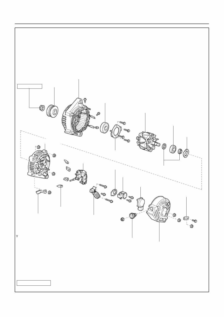
GENERATOR
COMPONENTS
B07729
111 (1,125, 81)
Drive End Flame
z Front Bearing
Retainer
Pulley
Rotor
Bearing Cover
z Rear Bearing
Generator
Washer
Rectifire End Frame
Rubber Insulator
Rectifire Holder
Voltage Regulator
Seal Plate
Brush Holder
Brush Holder Cover
Terminal Insulator
Rear End Cover
Plate Terminal
N·m (kgf·cm, ft·lbf) : Specified torque
z Non–reusable part
Wire Clip
CH–6
– CHARGING GENERATOR
783 AuthorĂ: DateĂ:
2000 MR2 (RM760U)
B00145
CH024–03
B07730
(a)
(b)
(c)
B07731
– CHARGING GENERATOR
CH–7
784 AuthorĂ: DateĂ:
2000 MR2 (RM760U)
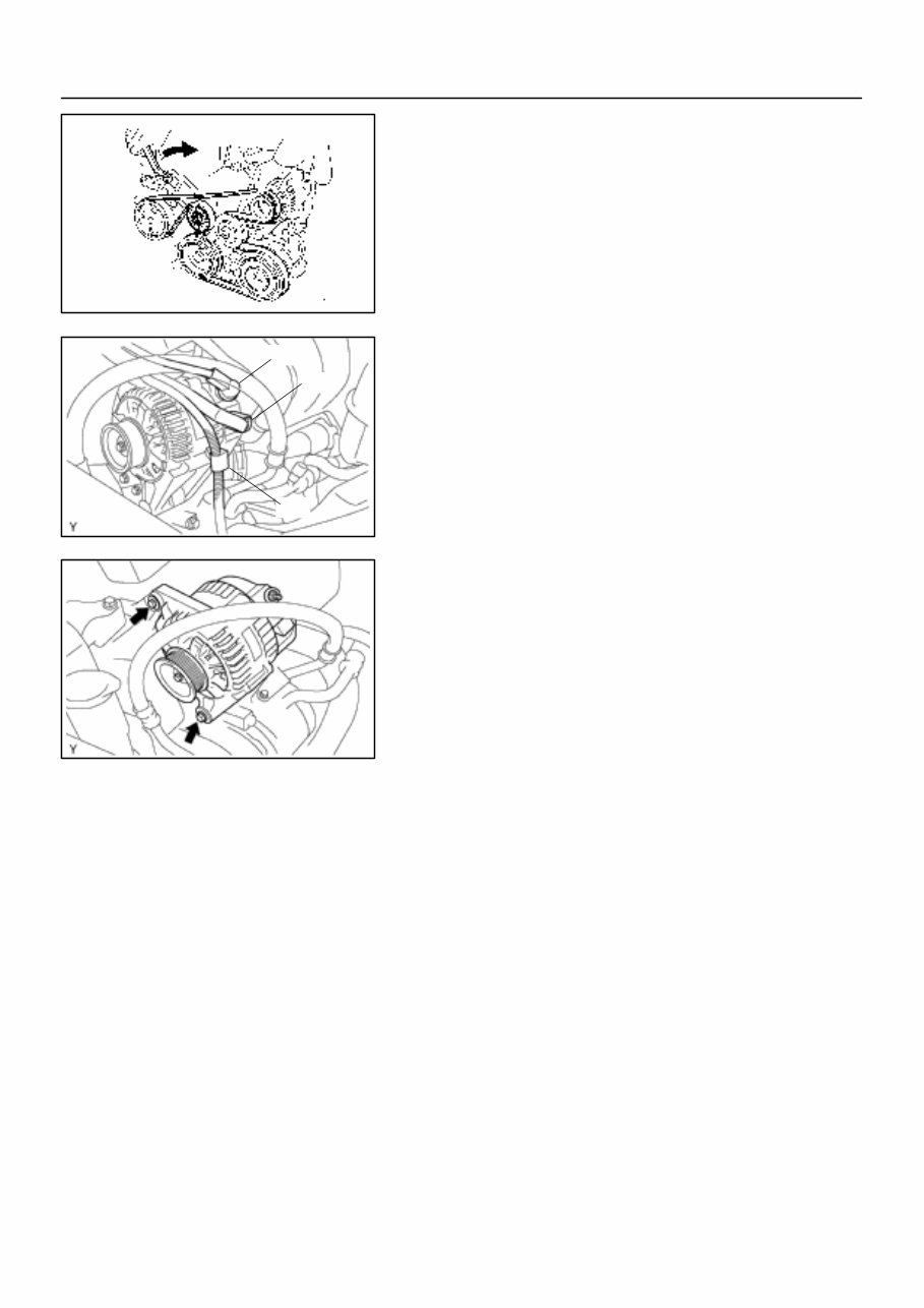
REMOVAL
1. REMOVE DRIVE BELT
Turn the drive belt tensioner slowly clockwise and loosen it.
Then, remove the drive belt and replace the drive belt tensioner
little by little and fix it quietly.
2. REMOVE RH ENGINE MOUNTING INSULATOR (See
page EM–54)
3. REMOVE GENERATOR
(a) Disconnect the wire clamp from the wire clip on the rectifi-
er end frame.
(b) Remove the cap and nut, and disconnect the generator
wire.
(c) Disconnect the generator connector.
(d) Remove the 2 bolts and generator.
B07732
Plate Terminal
CH025–03
B07733
B07734
B00210
Turn
SST (B)
SST (A)
B00224
SST (B)
Insert
SST (C)
CH–8
– CHARGING GENERATOR
785 AuthorĂ: DateĂ:
2000 MR2 (RM760U)
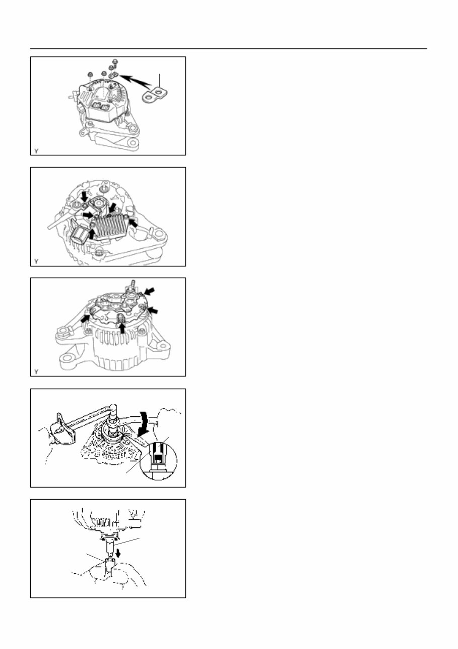
DISASSEMBLY
1. REMOVE REAR END COVER
(a) Remove the nut and terminal insulator.
(b) Remove the bolt, 3 nuts, plate terminal and end cover.
2. REMOVE BRUSH HOLDER AND VOLTAGE REGULA-
TOR
(a) Remove the brush holder cover from the brush holder.
(b) Remove the 5 screws, brush holder and voltage regulator.
(c) Remove the seal plate from the rectifier end frame.
3. REMOVE RECTIFIER HOLDER
(a) Remove the 4 screws and rectifier holder.
(b) Remove the 4 rubber insulators.
4. REMOVE PULLEY
(a) Hold SST (A) with a torque wrench, and tighten SST (B)
clockwise to the specified torque.
SST 09820–63010
Torque: 39 N·m (400 kgf·cm, 29 ft·lbf)
(b) Check that SST (A) is secured to the rotor shaft.
(c) Mount SST (C) in a vise.
(d) Insert SST (B) into SST (C), and attach the pulley nut to
SST (C).
B00237
SST (A)
SST (C)
Turn
B00322
Turn
SST (A)
SST (B)
B07735
Wire Clip
B09160
SST
– CHARGING GENERATOR
CH–9
786 AuthorĂ: DateĂ:
2000 MR2 (RM760U)
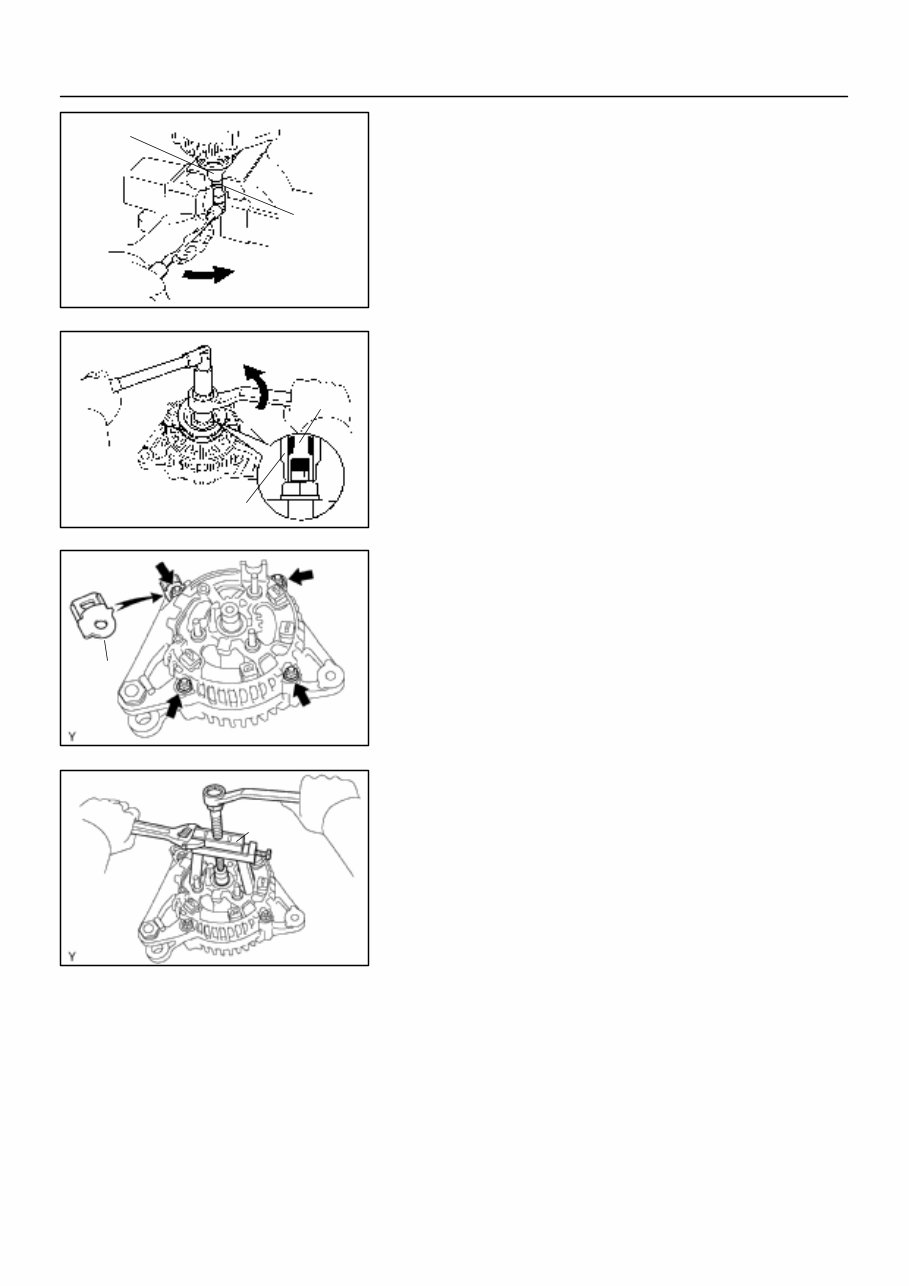
(e) To loosen the pulley nut, turn SST (A) in the direction
shown in the illustration.
NOTICE:
To prevent damage to the rotor shaft, do not loosen the
pulley nut more than one–half of a turn.
(f) Remove the generator from SST (C).
(g) Turn SST (B), and remove SST (A and B).
(h) Remove the pulley nut and pulley.
5. REMOVE RECTIFIER END FRAME
(a) Remove the 4 nuts and wire clip.
(b) Using SST, remove the rectifier end frame.
SST 09286–46011
(c) Remove the generator washer from the rotor
6. REMOVE ROTOR FROM DRIVE END FRAME
CH0784
Ohmmeter
Continuity
CH0DH–01
B02105
No Continuity
Ohmmeter
CH1023
B00240
Ohmmeter
Continuity
B00102
No Continuity
Ohmmeter
CH–10
– CHARGING GENERATOR
787 AuthorĂ: DateĂ:
2000 MR2 (RM760U)
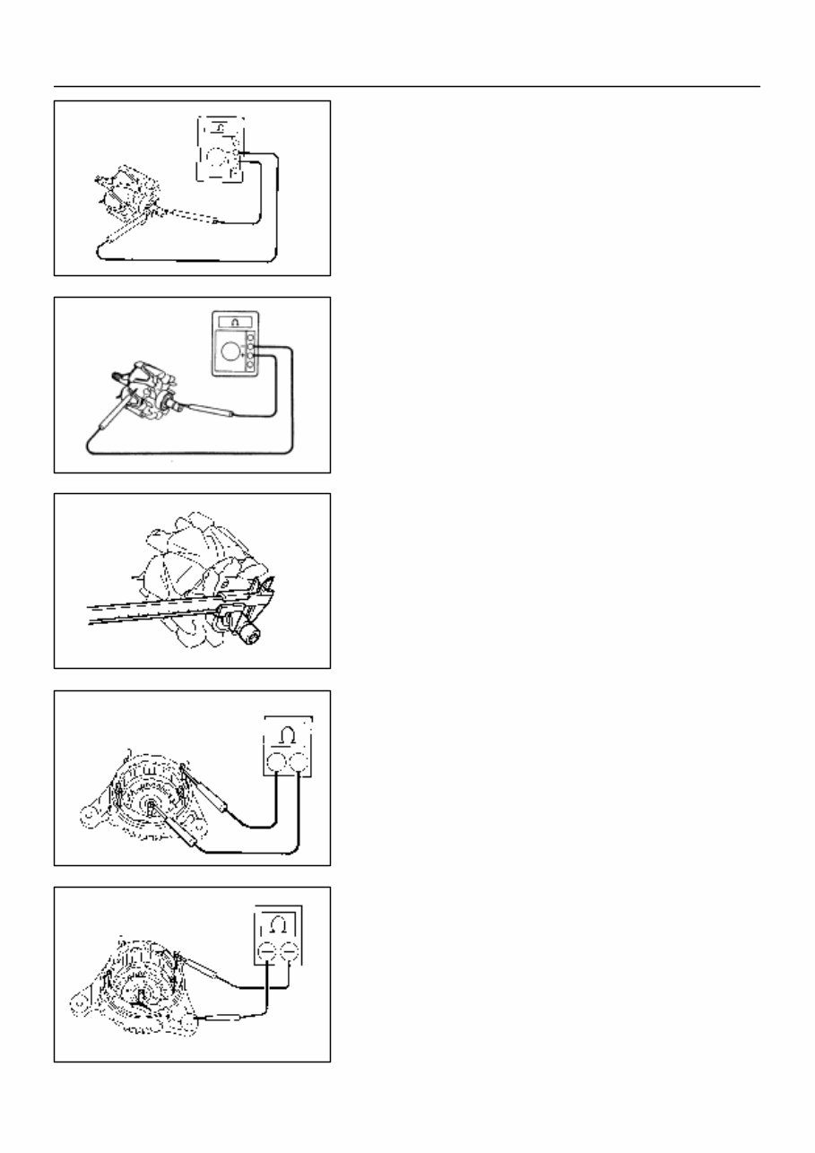
INSPECTION
1. INSPECT ROTOR
(a) Check the rotor for open circuit.
Using an ohmmeter, check that there is continuity be-
tween the slip rings.
Standard resistance: 2.1 – 2.5 Ω at 20°C (68°F)
If there is no continuity, replace the rotor.
(b) Check the rotor for ground.
Using an ohmmeter, check that there is no continuity be-
tween the slip ring and rotor.
If there is continuity, replace the rotor.
(c) Check that the slip rings are not rough or scored.
If rough or scored, replace the rotor.
(d) Using a vernier caliper, measure the slip ring diameter.
Standard diameter: 14.2 – 14.4 mm (0.559 – 0.567 in.)
Minimum diameter: 12.8 mm (0.504 in.)
If the diameter is less than minimum, replace the rotor.
2. INSPECT STATOR (DRIVE END FRAME)
(a) Check the stator for open circuit.
Using an ohmmeter, check that there is continuity be-
tween the coil leads.
If there is no continuity, replace the drive end frame assembly.
(b) Check the stator for ground.
Using an ohmmeter, check that there is no continuity be-
tween the coil lead and drive end frame.
If there is continuity, replace the drive end frame assembly.
You're Reading a Preview
What's Included?
Fast Download Speeds
Offline Viewing
Access Contents & Bookmarks
Full Search Facility
Print one or all pages of your manual
$39.99
Viewed 29 Times Today


Secure transaction
What's Included?
Fast Download Speeds
Offline Viewing
Access Contents & Bookmarks
Full Search Facility
Print one or all pages of your manual
$39.99
This workshop service repair manual covers the Toyota 1.8L1ZZ-FED (ZZW30) 4-cylinder in-line engine. Designed with professionals and DIY enthusiasts in mind, this manual provides comprehensive service and repair procedures while ensuring all technical specifications for the latest Toyota 1.8L1ZZ-FED (ZZW30) engine remain accurate.
- Introduction
- Tightening Torque
- Special Service Tools
- Maintenance Procedure
- Engine Mechanical
- Cylinderhead-Cylinder
- Crankcase-Crankshaft
- Piston & Connecting Rod
- Valve & Piston Pin
- Air Cleaner System
- Engine Fuel System
- Timing Gear & Camshaft
- Fuel Injection System
- Electronic Control System
- Fuel Pressure Regulator
- Cooling System
- Thermostat
- Intake System
- Engine Diagnostic
- Emission Control
- Lubrication System
- Ignition System
- Starting System
- System Circuit
- Charging System
- Alternator System
- Circuit Diagrams
- Service Specifications
This comprehensive manual features detailed exploded views and step-by-step processes with pictures and diagrams. It is fully printable for easy reference, making it a valuable resource for repairs, maintenance, and servicing of the Toyota 1.8L1ZZ-FED (ZZW30) engine.


