ENGINE > PRECAUTION 1.IGNITION SWITCH EXPRESSIONS 1. The type of ignition switch used on this model differs according to the specifications of the vehicle. The expressions listed in the table below are used in this section. Expression Ignition Switch (position) Engine Switch (condition) Ignition Switch off LOCK Off Ignition Switch on (IG) ON On (IG) Ignition Switch on (ACC) ACC On (ACC) Engine Start START Start
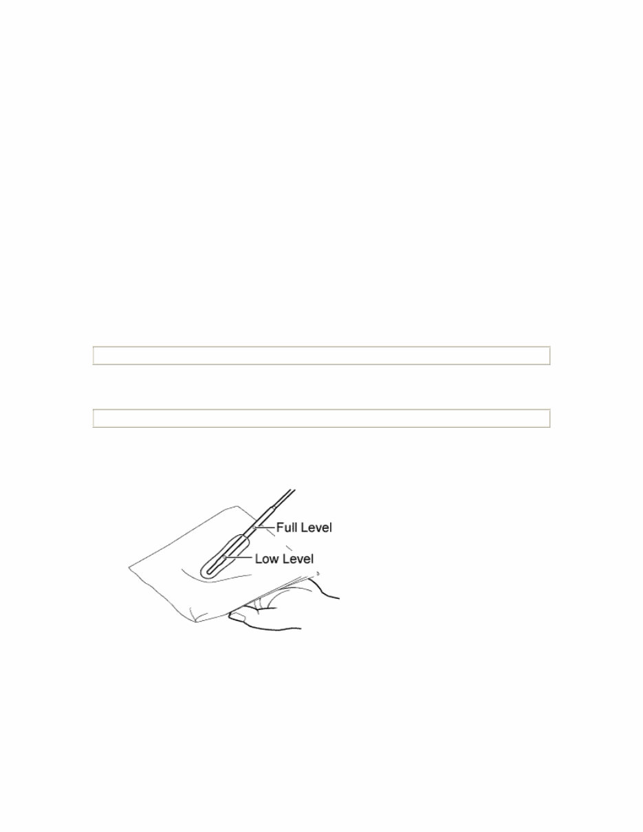
ENGINE > ON-VEHICLE INSPECTION 1. INSPECT ENGINE COOLANT 2. INSPECT ENGINE OIL 1. Check engine oil level. 1. Warm up the engine, stop the engine and wait 5 minutes. The oil level should be between the dipstick's low level mark and full level mark. If low, check for leakage and add oil up to the full level mark.
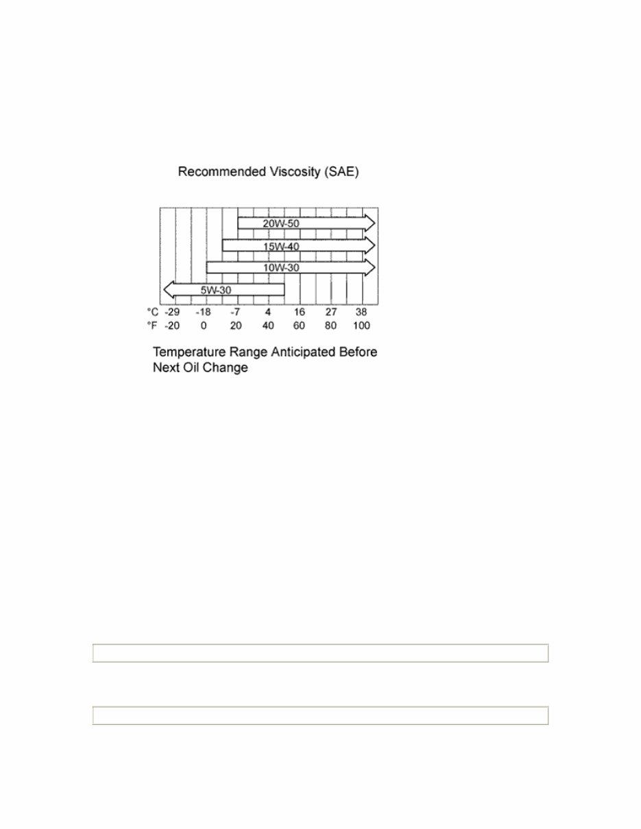
NOTICE: Do not fill with engine oil to above the full level mark. 2. Check engine oil quality. 1. Check the oil for deterioration, water contamination, discoloration and thinning. If the quality is visibly poor, replace the oil. Oil grade: 20W-50 and 15W-40: API grade SL or SM multigrade engine oil 10W-30 and 5W-30: API grade SL "Energy-Conserving" "Energy-Conserving SM or ILSAC multigrade engine oil" 3. INSPECT BATTERY 4. INSPECT AIR CLEANER FILTER ELEMENT SUB-ASSEMBLY
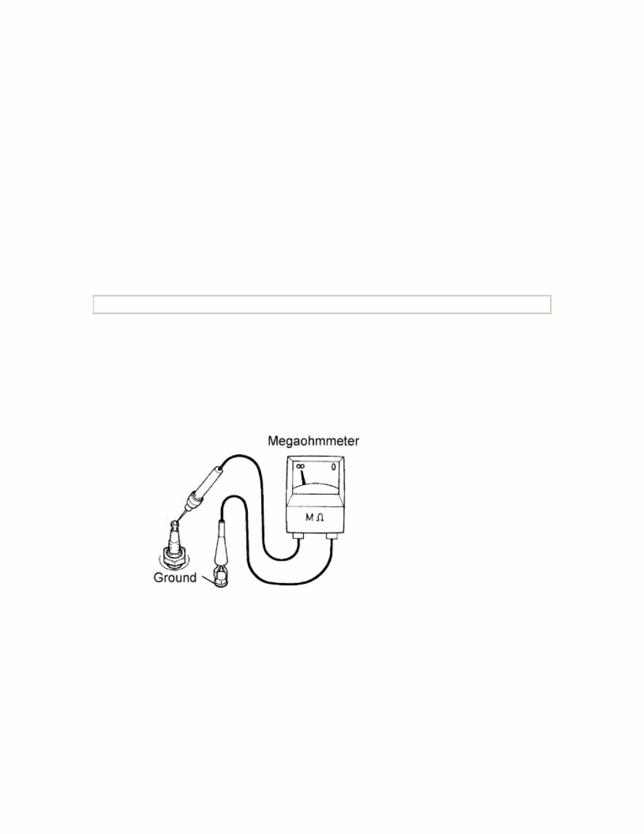
1. Remove the air cleaner filter element from the cylinder head cover sub-assembly. 2. Visually check that there is no dirt, clogging, /or damage to the air cleaner filter element. HINT: • If there is any dirt or a clog on the air cleaner filter element, clean it with compressed air. • If any dirt or a clog remains even after cleaning the air cleaner filter element with compressed air, replace it. 5. INSPECT SPARK PLUG NOTICE: • Do not use a wire brush for cleaning. • Do not attempt to adjust the electrode gap of a used spark plug. 1. Check the electron. 1. Using a megaohmmeter, measure the insulation resistance. Standard resistance: 10 MΩ or more If the resistance is less than the specified value, proceed to step (*3).
HINT: If a megaohmmeter is not available, perform the following simple inspection instead. 2. Alternative inspection method: 1. Quickly accelerate the engine to 4,000 rpm 5 times. 2. Remove the spark plug. 3. Visually check the spark plug. 4. If the electron is dry, the spark plug is functioning. Proceed to step 2. 5. If the electrode is damp, proceed to steps (*1), (*2) and (*3). 6. Install the spark plug. 3. Check the spark plug for any damage to its threads and insulator. (*1) If there is any damage, replace the spark plug. Recommended spark plug: Supplier Parts code DENSO K20HR-U11
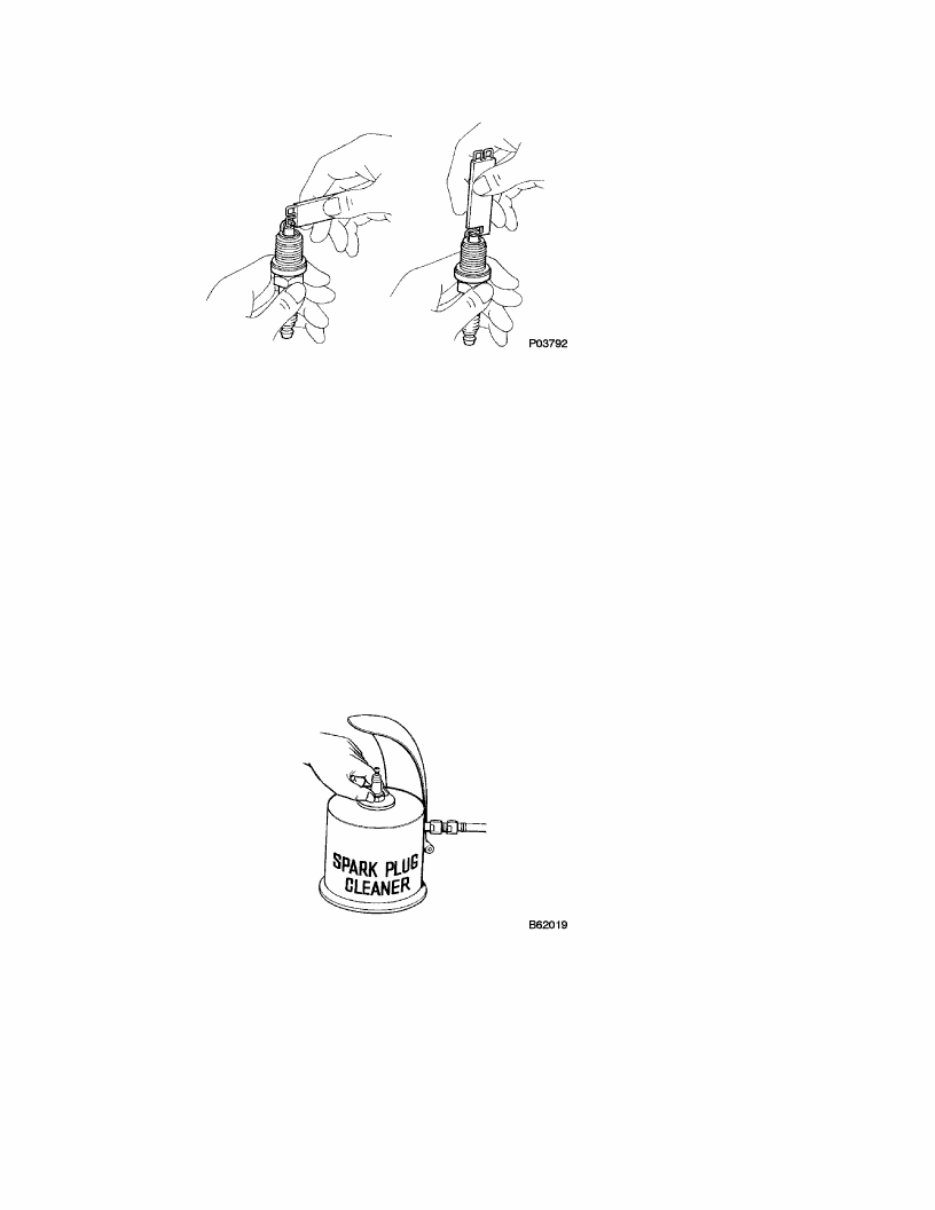
4. Check the spark plug electrode gap. (*2) Maximum electrode gap for used spark plug: 1.3 mm (0.051 in.) If the gap is greater than the maximum, replace the spark plug. Correct electrode gap for new spark plug: 1.0 to 1.1 mm (0.039 to 0.043 in.) NOTICE: Bend only the base of the ground electrode when adjusting the gap of a new spark plug. 5. Clean the spark plugs. (*3) If the electrode has traces of wet carbon, clean the electrode with a spark plug cleaner and then dry it. Air pressure: 588 kPa (6 kgf/cm 2 , 85psi)
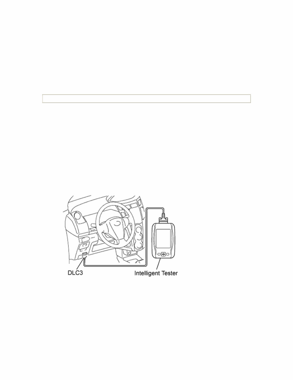
Duration: 20 seconds or less HINT: Only use the spark plug cleaner when the electrode is free of oil. If the electrode has traces of oil, use gasoline to clean off the oil before using the spark plug cleaner. 6. INSPECT IGNITION TIMING NOTICE: • Turn all the electrical systems and the A/C off. • Inspect the ignition timing with the cooling fan off. • When checking the ignition timing, shift the transmission to the neutral position. 1. Warm up and stop the engine. 2. When using the intelligent tester: 1. Connect the intelligent tester to the DLC3. 2. Turn the Ignition Switch on (IG). 3. Select the following menu items: Powertrain / Engine and ECT / Active Test / TE1 (TC) / ON.
HINT: Refer to the intelligent tester operator's manual for further information regarding the selection of Active Test. 4. Inspect the ignition timing during idling. Ignition timing: 8 to 12° BTDC 5. Select the following menu items: TE1 (TC) / OFF 6. Turn the Ignition Switch off. 7. Disconnect the intelligent tester from the DLC3. 3. When not using the intelligent tester: 1. Remove the air cleaner cap sub-assembly (). 2. Install the tester terminal of a timing light onto the position shown in the illustration. NOTICE: • Use a timing light that detects the first signal. • Wrap the wire harness with tape after checking.
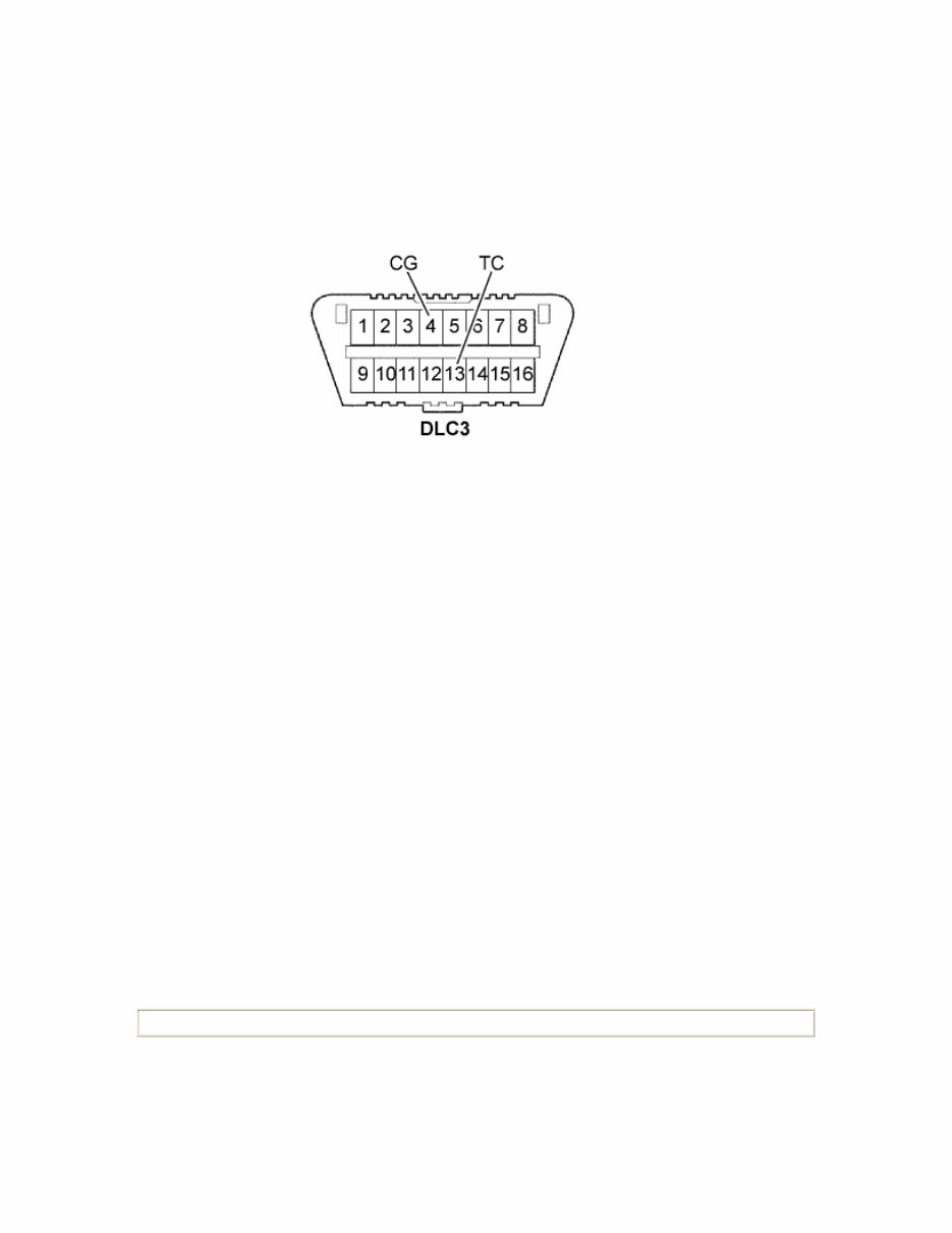
3. Using SST, connect terminals 13 (TC) and 4 (CG) of the DLC3. SST 09843-18040 NOTICE: Check the terminal numbers before connecting them. Connecting the wrong terminals could damage the engine. 4. Turn the Ignition Switch on (IG). 5. Inspect the ignition timing during idling. Ignition timing: 0 to 15° BTDC HINT: Run the engine speed at 1,000 to 1,300 rpm for 5 seconds, then check that the engine speed returns to the idling speed. 6. Disconnect terminals 13 (TC) and 4 (CG) of the DCL3. 7. Turn the Ignition Switch off. 8. Remove the timing light. 9. Install the air cleaner cap sub-assembly (). 7. INSPECT ENGINE IDLING SPEED NOTICE: • Turn all the electrical systems and the A/C off.
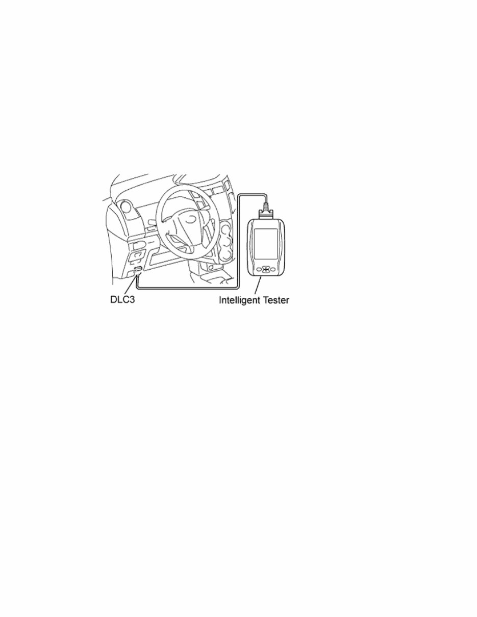
• Inspect the engine idling speed with the cooling fan off. • When checking the idling speed, shift the transmission to the neutral position. 1. Warm up and stop the engine. 2. When using the intelligent tester: 1. Connect the intelligent tester to the DLC3. 2. Turn the Ignition Switch on (IG). 3. Select the following menu items: Powertrain / Engine and ECT / Data List / Engine SPD. HINT: Refer to the intelligent tester operator's manual for further information regarding the selection of Data List. 4. Inspect the engine idling speed. Idling speed: 730 to 830 rpm 5. Turn the Ignition Switch off. 6. Disconnect the intelligent tester from the DCL3.
This workshop service repair manual covers the 1.0L 3-cylinder in-line transverse, 12-valve VVT-i, DOHC Toyota 1KR-FE engine. It is compatible with all Windows and Mac versions. The file size is 10 MB.
The manual includes detailed information on general description, torque specifications, engine mechanical, charging system, cooling system, emission control, engine control system, ignition system, starting system, drive belt components, camshaft-crankshaft, engine assembly, timing chain tension arm, cylinder head-cylinder, charging circuit, generator system, water pump-thermostat, integration relay, radiator-canister, parts location, circuit diagrams, SFI system, throttle body, accelerator pedal, engine coolant temperature sensor, knock sensor, and CVT system.
This manual is presented in electronic format, allowing you to print out the necessary pages and dispose of them after completing your task. It contains detailed illustrations, step-by-step written instructions, and necessary diagrams or pictures. Whether you are a do-it-yourself enthusiast or an experienced mechanic, this manual is your number one source for repair and service information. It provides an inexpensive way to keep your car working properly, guiding you through each service, repair, and maintenance procedure with its level of detail and illustrations.