

TECUMSEH HSSK40 HSSK50 4 CYCLE L HEAD Engine Full Service & Repair Manual
What's Included?
Fast Download Speeds
Online & Offline Access
Access PDF Contents & Bookmarks
Full Search Facility
Print one or all pages of your manual

This manual covers engine models:
ECV100 - 120, H22 - 80, HH40 - 70, HHM80, HM70 - 100,
HMSK70 - 110, HMXL70, HS40 - 50, HSK30 - 70, HSSK40 - 50,
HT30 - 35, HXL35, LAV30 - 50, LEV80 - 120, TNT100 - 120,
TVM125 - 220, TVXL170 - 220, TVS75 - 120, TVXL105 - 115,
V40 - 80, VH40 - 70, V60 - 70, VM70 - 100
Model numbers are located on the engine shroud.
3 TO 11 HP
4-CYCLE
L-HEAD
ENGINES
T E C H N I C I A N ’ S H A N D B O O K
TECUMSEH

i
C Tecumseh Products Company
1998
CONTENTS
CHAPTER 1 GENERAL INFORMATION ......................................................................................................... 1
ENGINE IDENTIFICATION ............................................................................................................................... 1
INTERPRETATION OF MODEL NUMBER ...................................................................................................... 1
SHORT BLOCKS .............................................................................................................................................. 2
FUEL ................................................................................................................................................................. 2
ENGINE OIL ..................................................................................................................................................... 3
TUNE-UP PROCEDURE .................................................................................................................................. 3
STORAGE ........................................................................................................................................................ 4
CHAPTER 2 AIR CLEANERS ........................................................................................................................ 5
GENERAL INFORMATION ............................................................................................................................... 5
OPERATION ..................................................................................................................................................... 5
COMPONENTS ................................................................................................................................................ 5
TROUBLESHOOTING OR TESTING .............................................................................................................. 5
SERVICE .......................................................................................................................................................... 6
DISASSEMBLY PROCEDURE ......................................................................................................................... 6
POLYURETHANE-TYPE FILTER ELEMENT ................................................................................................... 6
PAPER-TYPE FILTER ELEMENT .................................................................................................................... 6
CHAPTER 3 CARBURETORS AND FUEL SYSTEMS ................................................................................... 7
GENERAL INFORMATION ............................................................................................................................... 7
OPERATION ..................................................................................................................................................... 8
FUEL PRIMERS ............................................................................................................................................... 8
IMPULSE FUEL PUMPS .................................................................................................................................. 9
FLOAT STYLE CARBURETORS ..................................................................................................................... 9
DIAPHRAGM (PRESSURE DIFFERENTIAL) CARBURETORS ..................................................................... 9
COMPONENTS .............................................................................................................................................. 10
CARBURETOR IDENTIFICATION ................................................................................................................. 11
DUAL SYSTEM CARBURETORS .................................................................................................................. 11
SERIES 1 CARBURETORS ........................................................................................................................... 11
SERIES 3 & 4 CARBURETORS ..................................................................................................................... 11
DIAPHRAGM CARBURETORS ..................................................................................................................... 11
SERIES 6 CARBURETORS 4-CYCLE ........................................................................................................... 12
SERIES 8 ........................................................................................................................................................ 12
SERIES 9 ........................................................................................................................................................ 12
SERIES 10 (EMISSION) ................................................................................................................................. 12
NON-TECUMSEH CARBURETORS -- DELLORTO CARBURETOR ........................................................... 12
ENGINE TROUBLESHOOTING CHART ....................................................................................................... 13
CARBURETION TROUBLESHOOTING CHART ........................................................................................... 14
TESTING ........................................................................................................................................................ 15
SERVICE ........................................................................................................................................................ 15
CARBURETOR PRE-SETS AND ADJUSTMENTS ....................................................................................... 15
FINAL ADJUSTMENTS (NON-EMISSION ENGINES) .................................................................................. 16
NON-ADJUSTABLE CARBURETOR ............................................................................................................. 16
DISASSEMBLY PROCEDURE ....................................................................................................................... 17
FLOAT STYLE CARBURETORS ................................................................................................................... 17
DIAPHRAGM CARBURETORS ..................................................................................................................... 19
FLOAT ADJUSTING PROCEDURE ............................................................................................................... 19
INSPECTION .................................................................................................................................................. 20
ASSEMBLY ..................................................................................................................................................... 21
STANDARD SERVICE CARBURETORS ....................................................................................................... 24
CHAPTER 4 GOVERNORS AND LINKAGE ................................................................................................. 26
GENERAL INFORMATION ............................................................................................................................. 26
OPERATION ................................................................................................................................................... 26
INTERNAL COMPONENTS (VARIOUS STYLES) ......................................................................................... 26
TROUBLESHOOTING .................................................................................................................................... 26
ENGINE OVERSPEEDING ............................................................................................................................ 27
ENGINE SURGING ........................................................................................................................................ 27
SERVICE ........................................................................................................................................................ 27
GOVERNOR ADJUSTMENT .......................................................................................................................... 27
GOVERNOR ADJUSTMENT PROCEDURE FOR SHORT BLOCK INSTALLATIONS ................................. 27

ii
GOVERNOR GEAR AND SHAFT SERVICE ................................................................................................. 28
SPEED CONTROLS AND LINKAGE ............................................................................................................. 29
CHAPTER 5 REWIND STARTERS ................................................................................................................ 35
GENERAL INFORMATION ............................................................................................................................. 35
OPERATION ................................................................................................................................................... 35
COMPONENTS .............................................................................................................................................. 35
SERVICE ........................................................................................................................................................ 35
ROPE SERVICE ............................................................................................................................................. 35
RETAINER REPLACEMENT .......................................................................................................................... 36
STYLIZED REWIND STARTER (TVS, HM, TVM, TVXL), AND STAMPED STEEL STARTER
(HM, VM, TVM, TVXL) ............................................................................................................................... 36
STYLIZED REWIND STARTER WITH PLASTIC RETAINER ........................................................................ 37
STANDARD STAMPED STEEL AND CAST ALUMINUM STARTER (HM, VM) ............................................ 38
VERTICAL PULL STARTER HORIZONTAL ENGAGEMENT TYPE .............................................................. 39
VERTICAL PULL STARTER VERTICAL ENGAGEMENT TYPE ................................................................... 40
CHAPTER 6 ELECTRICAL SYSTEMS ....................................................................................................... 42
GENERAL INFORMATION ............................................................................................................................. 42
OPERATION ................................................................................................................................................... 42
STARTING CIRCUIT AND ELECTRIC STARTERS ....................................................................................... 42
CHARGING CIRCUIT ..................................................................................................................................... 42
CONVERTING ALTERNATING CURRENT TO DIRECT CURRENT ............................................................ 43
HALF WAVE RECTIFIER SINGLE DIODE .................................................................................................... 43
FULL WAVE RECTIFIER BRIDGE RECTIFIER ............................................................................................. 43
COMPONENTS .............................................................................................................................................. 43
BATTERY ........................................................................................................................................................ 43
WIRING ........................................................................................................................................................... 43
ELECTRICAL TERMS .................................................................................................................................... 44
BASIC CHECKS ............................................................................................................................................. 45
TROUBLESHOOTING ELECTRICAL STARTER CIRCUIT FLOW CHART .................................................. 46
TROUBLESHOOTING ELECTRICAL CHARGING CIRCUIT FLOW CHART ............................................... 47
TESTING PROCEDURE ................................................................................................................................ 48
STARTING CIRCUIT ...................................................................................................................................... 48
CHARGING CIRCUIT ..................................................................................................................................... 48
VOLTAGE REGULATIONS ............................................................................................................................. 56
LOW OIL SHUTDOWN SWITCHES ............................................................................................................... 56
SERVICE ........................................................................................................................................................ 57
12 VOLT OR 120 VOLT ELECTRIC STARTERS WITH EXPOSED SHAFT ................................................. 57
12 VOLT D.C. OR 120 VOLT A.C. ELECTRIC STARTERS WITH THE STARTER GEAR UNDER
THE CAP ASSEMBLY ............................................................................................................................... 57
INSPECTION .................................................................................................................................................. 58
CHAPTER 7 FLYWHEEL BRAKE SYSTEMS ............................................................................................... 59
GENERAL INFORMATION ............................................................................................................................. 59
OPERATION ................................................................................................................................................... 59
BOTTOM SURFACE SYSTEM ....................................................................................................................... 59
INSIDE EDGE SYSTEM ................................................................................................................................. 60
COMPONENTS .............................................................................................................................................. 60
SERVICE ........................................................................................................................................................ 61
FLYWHEEL REMOVAL .................................................................................................................................. 61
BRAKE LEVER AND PAD .............................................................................................................................. 61
IGNITION GOUNDOUT TERMINAL ............................................................................................................... 61
STARTER INTERLOCK SWITCH .................................................................................................................. 62
CONTROL CABLE .......................................................................................................................................... 62
BRAKE BRACKET REPLACEMENT .............................................................................................................. 62
CHAPTER 8 IGNITION .................................................................................................................................. 63
GENERAL INFORMATION ............................................................................................................................. 63
OPERATION ................................................................................................................................................... 63
SOLID STATE IGNITION SYSTEM (CDI) ...................................................................................................... 63
MAGNETO IGNITION SYSTEM (POINTS) .................................................................................................... 63
IDENTIFICATION OF TECUMSEH IGNITION SYSTEMS ............................................................................. 64
COMPONENTS .............................................................................................................................................. 64
IGNITION TROUBLESHOOTING .................................................................................................................. 66

iii
TESTING PROCEDURE ................................................................................................................................ 67
SERVICE ........................................................................................................................................................ 68
SPARK PLUG SERVICE ................................................................................................................................ 68
CONDITIONS CAUSING FREQUENT SPARK PLUG FOULING .................................................................. 68
IGNITION TIMING PROCEDURE .................................................................................................................. 68
SERVICE TIPS ............................................................................................................................................... 71
CHAPTER 9 INTERNAL ENGINE AND CYLINDER ..................................................................................... 72
GENERAL INFORMATION ............................................................................................................................. 72
OPERATION ................................................................................................................................................... 72
4-CYCLE ENGINE THEORY .......................................................................................................................... 72
LUBRICATION SYSTEMS .............................................................................................................................. 73
COUNTERBALANCE SYSTEMS ................................................................................................................... 73
COMPONENTS .............................................................................................................................................. 74
ENGINE OPERATION PROBLEMS ............................................................................................................... 75
TESTING ........................................................................................................................................................ 77
ENGINE KNOCKS .......................................................................................................................................... 77
ENGINE OVERHEATS ................................................................................................................................... 77
SURGES OR RUNS UNEVENLY ................................................................................................................... 77
ENGINE MISFIRES ........................................................................................................................................ 77
ENGINE VIBRATES EXCESSIVELY .............................................................................................................. 78
BREATHER PASSING OIL ............................................................................................................................. 78
EXCESSIVE OIL CONSUMPTION ................................................................................................................. 78
LACKS POWER ............................................................................................................................................. 78
SERVICE ........................................................................................................................................................ 79
DISASSEMBLY PROCEDURE ....................................................................................................................... 79
CYLINDERS ................................................................................................................................................... 81
CYLINDER HEADS ........................................................................................................................................ 82
PISTONS, RINGS AND CONNECTING RODS ............................................................................................. 82
CRANKSHAFTS AND CAMSHAFTS ............................................................................................................. 84
VALVES .......................................................................................................................................................... 85
CRANKCASE BREATHERS ........................................................................................................................... 86
CYLINDER COVER, OIL SEAL, AND BEARING SERVICE .......................................................................... 87
CRANKSHAFT BEARING SERVICE ............................................................................................................. 88
COUNTERBALANCE SERVICE .................................................................................................................... 89
FLYWHEEL SERVICE .................................................................................................................................... 89
CHAPTER 10 ENGINE SPECIFICATIONS ................................................................................................... 90
FOUR CYCLE TORQUE SPECIFICATIONS ................................................................................................. 91
ENGINE SPECIFICATIONS STANDARD POINT IGNITION ......................................................................... 93
SOLID STATE AND EXTERNAL IGNITION ................................................................................................... 97
CHAPTER 11 EDUCATION MATERIALS AND TOOLS ............................................................................. 102
DECIMAL / FRACTION CONVERSIONS ..................................................................................................... 105
SEARS CRAFTSMAN CROSS REFERENCE SUPPLEMENT INCLUDED IN BACK OF BOOK
1
CHAPTER 1 GENERAL INFORMATION
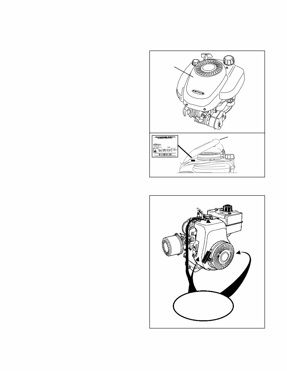
ENGINE IDENTIFICATION
Tecumseh engine model, specification, and serial
numbers or (date of manufacture, DOM) are stamped into
the blower housing or located on a decal on the engine
in locations as illustrated (diag. 1 & 2).
NOTE: On some LEV engines, a cover bezel must be
removed to provide access to the identification decal
(diag. 1).
The engine identification decal also provides the
applicable warranty code and oil recommendations (diag.
3).
Emissionized engines that meet the California Air
Resource Board (C.A.R.B.) or the Environmental
Protection Agency (E.P.A.) standards will include
additional required engine information on the engine decal
(diag. 3).
INTERPRETATION OF MODEL NUMBER
The first letter designation in a model number indicates
basic type of engine.
V - Vertical Shaft
LAV - Lightweight Aluminum Vertical
VM - Vertical Medium Frame
TVM - Tecumseh Vertical (Medium Frame)
VH - Vertical Heavy Duty (Cast Iron)
TVS - Tecumseh Vertical Styled
TNT - Toro N’ Tecumseh
ECV - Exclusive Craftsman Vertical
TVXL - Tecumseh Vertical Extra Life
LEV - Low Emissions Vertical
H - Horizontal Shaft
HS - Horizontal Small Frame
HM - Horizontal Medium Frame
HHM - Horizontal Heavy Duty (Cast Iron) Medium Frame
HH - Horizontal Heavy Duty (Cast Iron)
ECH - Exclusive Craftsman Horizontal
HSK - Horizontal Snow King
HS50 67355H SER 4091D
1
2
COVER BEZEL
MODEL AND
D.O.M. NUMBER
DECAL
LOCATED
UNDER COVER
(IF SO EQUIPPED)
PRESS IN AND LIFT
HERE TO RELEASE
COVER
˙
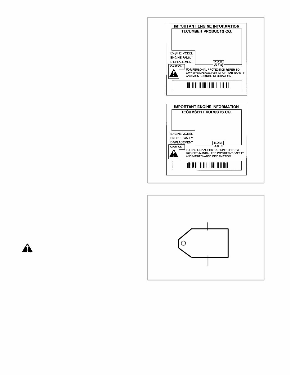
2
The number designations following the letter indicate the
horsepower or cubic inch displacement.
The number following the model number is the
specification number. The last three numbers of the
specification number indicate a variation to the basic
engine specification.
The serial number or D.O.M. indicates the production date.
Using model LEV115-57010B, serial 8105C as an
example, interpretation is as follows:
LEV115-57010B is the model and specification number
LEV Low Emissions Vertical
115 Indicates a 11.5 cubic inch displacement
57010B is the specification number used for properly
identifying the parts of the engine
8105C is the serial number
8 first digit is the year of manufacture (1998)
105 indicates calendar day of that year (105th day
or April 15, 1998)
C represents the line and shift on which the
engine was built at the factory.
Engine Family: Engine Tracking Information
SHORT BLOCKS
New short blocks are identified by a tag marked S.B.H.
(Short Block Horizontal) or S.B.V. (Short Block Vertical).
Original model identification numbers of an engine should
always be transferred to a new short block for correct
parts identification (diag. 4).
THIS SYMBOL POINTS OUT IMPORTANT
SAFETY INSTRUCTIONS WHICH IF NOT
FOLLOWED COULD ENDANGER THE
PERSONAL SAFETY OF YOURSELF AND
OTHERS. FOLLOW ALL INSTRUCTIONS.
FUEL REGULAR UNLEADED
OIL, SAE 30 (BELOW 32
o
F SAE 5W30)
LEV115 57010B (D)
STP185U1G1RA
8105C
THIS ENGINE MEETS 1995-1998
CALIF. EMISSION REGULATOR FOR
ULGE ENGINES AS APPLICBLE
FUEL: REGULAR UNLEADED OIL: USE SEA30
LEV115 57010B (D)
STP185U1G1RA
8105C
SHORT BLOCK IDENTIFICATION TAG
SBV-2316
SER 4291
SERIAL NUMBER
SBV OR SBH IDENTIFICATION NUMBER
4
3
FUEL
Tecumseh strongly recommends the use of fresh clean unleaded regular gasoline in all engines. Unleaded gasoline
burns cleaner, extends engine life and promotes better starting by reducing build-up of combustion chamber deposits.
REFORMULATED AND OXYGENATED FUELS
Reformulated fuels containing no more than 10% Ethanol, 15% MTBE, 15% ETBE or premium gasoline can be used
if unleaded regular gasoline is not available. Leaded fuel may be used in countries where unleaded fuel is not available.
NEVER USE FUEL CONTAINING METHANOL.

3
ENGINE OIL
Use a clean, high quality detergent oil. Be sure original container is marked: A.P.I. service SF thru SJ. The use of
multigrade oil may increase oil consumption under high temperature, high load applications.
NOTE: DO NOT USE SAE10W40 OIL.
For summer (above 32°F, 0
o
C) use SAE 30 oil part # 730225 (1 quart, .946 liter container) in high temperature, high
load applications.
S.A.E.10W30 is an acceptable substitute.
For winter (below 32°F, 0
o
C) use S.A.E. 5W30 oil part # 730226 (1 quart, .946 liter container)
S.A.E.10W is an acceptable substitute.
S.A.E. 0W30 should only be used when ambient temperature is below 0
o
F, -18
o
C.
CAPACITIES: EUROPA MODELS
Engine Model Oz. mL. Oz. mL.
LAV30-50, TVS75-120, LEV80-120 21 630 Vantage 21 630
ECV100-120, TNT100-120 21 630 Prisma 21 630
V & VH50, 60, 70 27 810 Synergy 21 630
TVM 125, 140 27 810 Synergy "55" 27 810
TVM & TVXL 170, 195, 220 32 960 Spectra 21 630
VM70, 80, 100 32 960 Futura 21 630
VH100 50 1500 Centura 21 630
H & HSK30, 35, HS & HSK40, 50 21 630 HTL 21 630
H, HH & HSK50, 60, 70 19 570 BVS 21 630
HM & HMSK70, 80, 100 26 720 BH Series 21 630
Geo Tech Series 35-50 21 630
Oil Change Intervals. Change the oil after the first two (2) hours of operation and every 25 hours thereafter, or more
often if operated under dusty or dirty conditions, extreme temperature, or high load conditions.
Oil Check. Check the oil each time the equipment is used or every 5 hours. Position the equipment so the engine is
level when checking the oil.
CAUTION: REMOVE THE SPARK PLUG WIRE BEFORE DOING ANY SERVICE WORK ON THE ENGINE.
Oil Change Procedure: Locate the oil drain plug. On some units this plug is located below the deck through the
bottom of the mounting flange. Other units drain at the base of the engine above the deck or frame. If access to the
drain plug is restricted by the equipment it may be necessary to drain the oil by tipping the mower in a position that
would allow the oil to drain out of the fill tube.
On units that the drain plug is accessible, remove the plug and allow the oil to drain into a proper receptacle. Always
make sure that drain oil is disposed of properly.
Once the oil is drained, reinstall the plug and fill the engine with new oil to the proper capacity.
TUNE-UP PROCEDURE.
The following is a minor tune-up procedure. When this procedure is completed, the engine should operate properly.
Further repairs may be necessary if the engine's performance remains poor.
CAUTION: REMOVE THE SPARK PLUG WIRE BEFORE DOING ANY SERVICE WORK ON THE ENGINE.
1. Service or replace the air cleaner as needed.
2. Inspect the level and condition of the oil and change or add oil as required.
3. Remove the blower housing and clean all dirt, grass or debris from the intake screen, cylinder head, cylinder
cooling fins, carburetor, governor levers and linkage.
4. Make sure the fuel tank, fuel filter and fuel line are clean. Replace any worn or damaged governor springs or
linkage. Make the proper governor adjustments and carburetor presets where required.
4
5. When replacing the spark plug, consult the parts breakdown for the proper spark plug to be used in the engine being
serviced. Set the spark plug gap to .030" (.762 mm) and install the spark plug in the engine. Tighten the spark plug
to 15 foot pounds of torque (20.4 Nm). If a torque wrench isn’t available, screw the spark plug in as far as possible by
hand, and use a spark plug wrench to turn the spark plug 1/8 to 1/4 turn further if using the old spark plug, or 1/2 turn
further if using a new spark plug.
6. Make sure all ignition wires are free of abrasions or breaks and are properly routed so they will not rub on the
flywheel.
7. Properly reinstall the blower housing, gas tank, fuel line and air cleaner assembly if removed.
8. Make sure all remote cables are properly adjusted for proper operation. See chapter 4 under "Speed Controls and
Linkage".
9. Reinstall the spark plug wire, add fuel and oil as necessary, and start the engine.
STORAGE: (IF THE ENGINE IS TO BE UNUSED FOR 30 DAYS OR MORE)
CAUTION: NEVER STORE THE ENGINE WITH FUEL IN THE TANK INDOORS , IN ENCLOSED POORLY
VENTILATED AREAS WHERE FUEL FUMES MAY REACH AN OPEN FLAME, SPARK OR PILOT LIGHT
AS ON A FURNACE, WATER HEATER, CLOTHES DRYER OR OTHER GAS APPLIANCE.
Gasoline can become stale in less than 30 days and form deposits that can impede proper fuel flow and engine operation.
To prevent deposits from forming, all gasoline must be removed from the fuel tank and the carburetor. An acceptable
alternative to removing all gasoline is adding a fuel stabilizer to the gasoline. Fuel stabilizer (such as Tecumseh's Part
No. 730245) is added to the fuel tank or storage container. Always follow the mix ratio found on the stabilizer container.
Run the engine at least 10 minutes after adding the stabilizer to allow it to reach the carburetor.
CAUTION: THE USE OF SOME ANTI-ICING ADDITIVES MAY CREATE A METHANOL FUEL BLEND. DO NOT
USE ADDITIVES THAT CONTAIN METHANOL. FUEL CONDITIONERS THAT CONTAIN ISOPROPYL ALCOHOL
IS RECOMMENDED.
Draining the Fuel System:
CAUTION: DRAIN THE FUEL INTO AN APPROVED CONTAINER OUTDOORS, AND AWAY FROM ANY
OPEN FLAME OR COMBUSTION SOURCE. BE SURE THE ENGINE IS COOL.
1. Remove all gasoline from the fuel tank by running the engine until the engine stops, or by draining the fuel tank by
removing the fuel line at the carburetor or fuel tank. Be careful not to damage the fuel line, fittings, or fuel tank.
2. Drain the carburetor by pressing upward on the bowl drain (if equipped) which is located on the bottom of the
carburetor bowl. On carburetors without a bowl drain, the carburetor may be drained by loosening the bowl nut on
the bottom carburetor one full turn. Allow to completely drain and retighten the bowl nut being careful not to
damage the bowl gasket when tightening.
3. If "Gasohol" has been used, complete the above procedure and then put one half pint of unleaded gasoline into
the fuel tank and repeat the above procedure. If Gasohol is allowed to remain in the fuel system during storage,
the alcohol content will cause rubber gaskets and seals to deteriorate.
Change Oil: If the oil has not been changed recently, this is a good time to do it.
Oil Cylinder Bore:
1. Disconnect the spark plug wire and ground the wire to the engine. Remove the spark plug and put 1/2 ounce
(14 ml) of clean engine oil into the spark plug hole.
2. Cover the spark plug hole with a shop towel.
3. Crank the engine over slowly several times.
CAUTION: AVOID SPRAY FROM SPARK PLUG HOLE WHEN SLOWLY CRANKING ENGINE OVER.
4. Install the spark plug and connect the spark plug wire.
Clean Engine: Remove the blower housing and clean all dirt, grass or debris from the intake screen, cylinder head,
cylinder cooling fins, carburetor, governor levers and linkage.
5
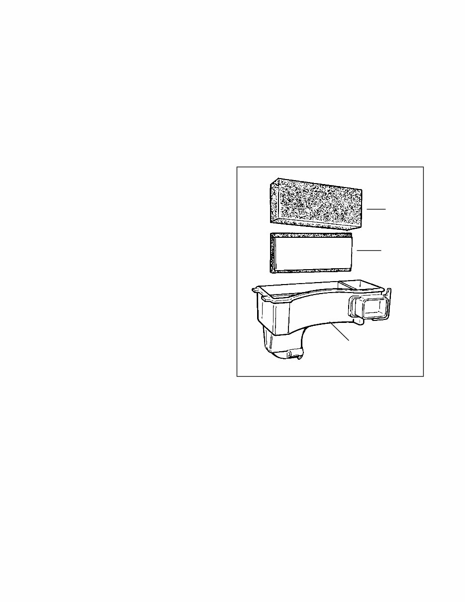
GENERAL INFORMATION
The air cleaner is the device used to eliminate dust and
dirt from the air supply. Filtered air is necessary to assure
that abrasive particles are removed before entering the
carburetor and combustion chamber. Dirt allowed into the
engine will quickly wear the internal components and
shorten the life of the engine.
Tecumseh engines use either a polyurethane or a paper-
type air filter system. A polyurethane pre-cleaner or a flocked
screen may be used in conjunction with the main filter.
Snow King
®
engines do not use an air filter.
Extremely dirty conditions may require more frequent filter
cleaning or replacement.
OPERATION
The outer cover encapsulates the air filter element(s) and
prevents large particles from entering the filter box. Air is
filtered through the pre-cleaner or flocked screen (if
equipped) and the polyurethane or paper filter element. Pre-
cleaners or flocked screens provide additional air cleaning
capacity.
In Tecumseh's Kleen Aire
®
system, air is drawn in through
a rotating screen or recoil cover to be centrifugally cleaned
by the flywheel before the air is drawn into the air filter.
COMPONENTS
The cover holds the filter element and prevents large debris
from entering the filter element.
The polyurethane wrap pre-filter is used on XL or XL/C
engine models with paper filter elements.
The paper or polyurethane filter element is the main
filter to trap dust and dirt. Dry-type paper elements have
treated paper folded for increased surface area and rubber-
like sealing edges. The polyurethane filter uses an oil film
to trap fine particles found in dust.
The flocked screen is used as an additional filter on XL
or XL/C engine models that use a polyurethane filter
element.
TROUBLESHOOTING OR TESTING
If the engine's performance is unsatisfactory (needs
excessive carburetor adjustments, starts smoking
abnormally, loses power), the first engine component to be
checked is the air cleaner. A dirt restricted or an oil soaked
element will cause noticeable performance problems. A
polyurethane element may be cleaned following the service
procedure listed under "Service" in this chapter. A paper-
type air filter should only be replaced. A paper-type element
cannot have an oil film present on the paper. Follow the
procedure listed in the "Service" section of this chapter for
replacement. Re-try the engine after filter replacement or
service. If the problem persists after filter service, see
Chapter 9 under "Engine Operation Problems" for additional
causes.
CHAPTER 2 AIR CLEANERS
1
2
COVER
FOAM
ELEMENT
FLOCKED SCREEN
AIR CLEANER
BODY
AIR CLEANER
BODY
PAPER
ELEMENT
POLYURETHANE
WRAP
COVER
(diag 1 & 2)
SEALING NUTS
6
This type of air filter can be serviced when restricted with dust or dirt. Wash the filter or pre-cleaner in a liquid detergent
and water solution until all the dirt is removed. Rinse in clear water to remove the detergent solution. Squeeze the
element (do not twist) to remove the excess water. Wrap the element in a clean cloth and squeeze it (do not twist) until
completely dry.
Re-oil the element by applying engine oil and squeezing it vigorously to distribute the oil. Roll the element in a cloth and
squeeze it (do not twist) to remove the excess oil.
Clean the air cleaner housing and cover being careful not to allow dirt to fall into the carburetor or intake pipe.
PAPER -TYPE FILTER ELEMENT
Paper type air filter elements can only be serviced by replacement. Do not attempt to clean a paper filter element.
3
AIR CLEANER
BODY
1/2" (12.7 mm)
FOAM
WITH FLOCKED
SCREEN
ATTACHED
FOAM
ELEMENT
1. Unlock the tabs or remove the screws, wingnuts or
snaps holding the air cleaner cover in place.
2. Remove the hex nuts holding the element down if
equipped. New nuts are supplied with a new filter and
MUST be used for proper sealing.
3. Clean the excess contaminants out of the air cleaner
body before removing the old element.
4. Remove the old element and the polyurethane pre-
cleaner if equipped.
5. On air cleaners that use a flocked screen under the
polyurethane element, remove the air cleaner assembly
from the carburetor before removing the flocked screen.
This prevents dirt from entering the carburetor (diag 3).
6. Clean the inside of the cover and body, remove the old
gasket between the carburetor and the air cleaner
assembly.
7. Reinstall the air cleaner assembly using a new gasket.
8. Use the reverse procedure for reassembly. When
installing the foam polyurethane pre-cleaner, make sure
the seam is installed to the outside to prevent gaps
between the paper element and the pre-cleaner.
POLYURETHANE-TYPE FILTER ELEMENT
SERVICE
Service on the polyurethane element (cleaning and oiling) is recommended every three months or every twenty five
operating hours, whichever comes first. Extremely dirty or dusty conditions may require daily cleanings.
The paper filter element should be replaced at least once a year or more frequently if operated in dusty or dirty conditions.
NOTE: NEVER RUN THE ENGINE WITHOUT THE COMPLETE AIR CLEANER ASSEMBLY INSTALLED ON THE
ENGINE. ALWAYS REPLACE THE FILTER ELEMENT WITH THE PROPER TECUMSEH ORIGINAL REPLACEMENT
PART.
DISASSEMBLY PROCEDURE
You're Reading a Preview
What's Included?
Fast Download Speeds
Online & Offline Access
Access PDF Contents & Bookmarks
Full Search Facility
Print one or all pages of your manual
$31.99
Viewed 26 Times Today


Secure transaction
What's Included?
Fast Download Speeds
Online & Offline Access
Access PDF Contents & Bookmarks
Full Search Facility
Print one or all pages of your manual
$31.99
Get instant access to the Complete Factory Service Repair Workshop Manual without any extra fees or expiry dates. This Professional Manual is suitable for your computer, tablet, or smartphone and covers all repairs, servicing, and troubleshooting procedures. It contains detailed photos, diagrams, step-by-step instructions, and highly detailed exploded diagrams and pictures, making it useful for both professional Mechanics and DIY enthusiasts.
Print out a single page or the entire manual as per your choice. This Manual can be used on multiple computers without any limitations or trial periods and can be used for life without the need for renewal or extra payment. It is fully compatible with all Windows and MAC Computers.


