

Robin EX27 parts manual
What's Included?
Fast Download Speeds
Online & Offline Access
Access PDF Contents & Bookmarks
Full Search Facility
Print one or all pages of your manual

PARTS
MANUAL
EX27
ENGINE
Models
PUB-EP1679
Rev. 09/08

© Copyright 2008 Robin America, Inc.
905 Telser Road • Lake Zurich, IL 60047 • Phone: 630-350-8200 • Fax: 630-350-8212
e-mail: sales@robinamerica.com • www.subarupower.com
EX27 - 3 - 09-08
HOW TO USE THIS MANUAL
Robin engines are identified by MODEL, SPECIFICATION, and CODE NUMBER. For each
model there may be many different versions called specifications. Each specification will be
unique in some way. The difference may only be the paint color or it may have a different type
of PTO or some other significant difference.
In order the identify the correct service part number, it is important to confirm the specifica-
tion and code numbers for your engine. The specification and code number together are
know as the PRODUCT NUMBER.
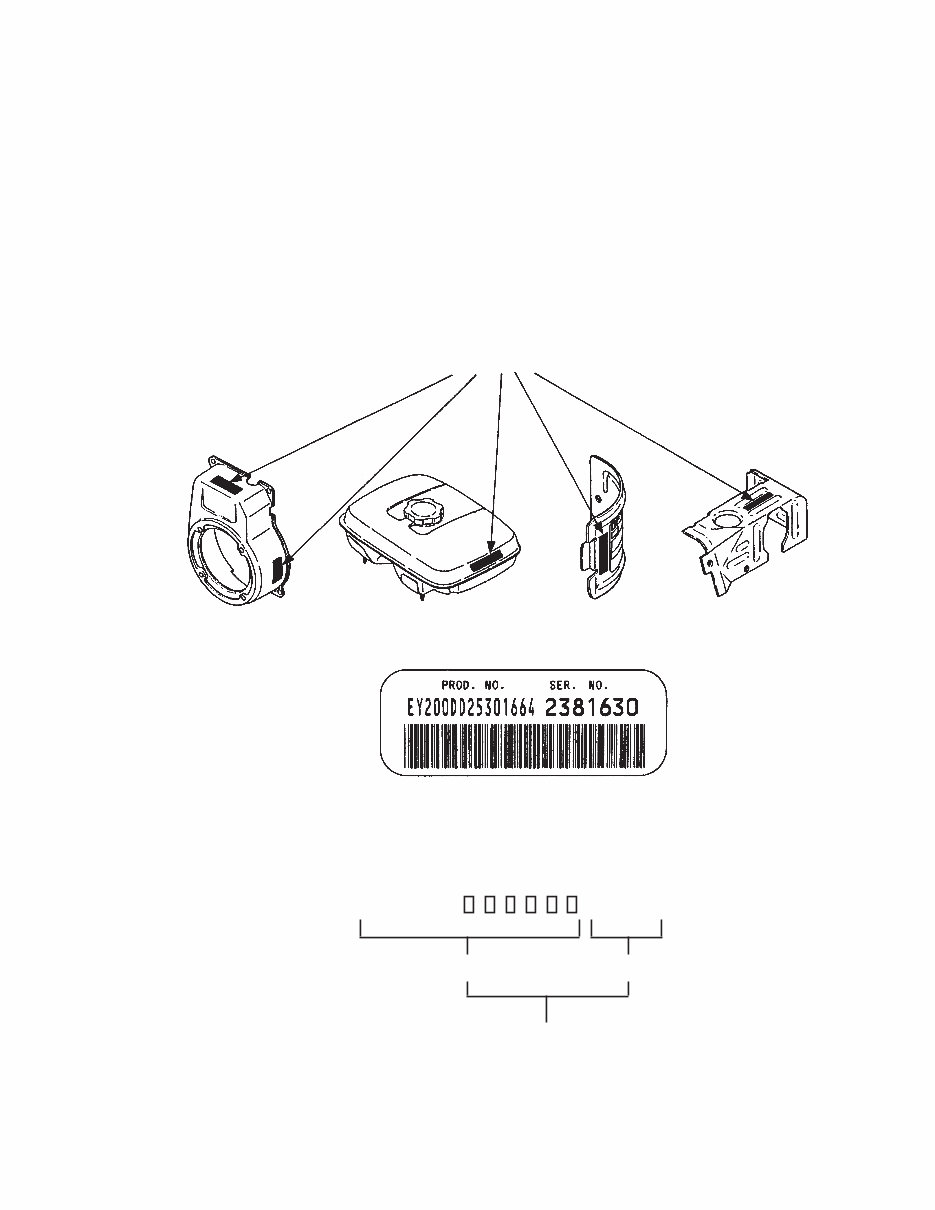
All Robin 4 cycle engines have a Product Number label similar to the label illustrated below.
The Product Number Label has a 15 digit alphanumeric string that consists of the
SPECIFICATION (SPEC) number (11 digits) and the CODE number (4 digits). Please
note the illustration below:
X X X X
SPEC NO. (11 digits) CODE NO. (4 digits)
PRODUCT NO. (15 digits)
E X 2 7 0
EX27 - 4 - 09-08
MANUAL LAYOUT
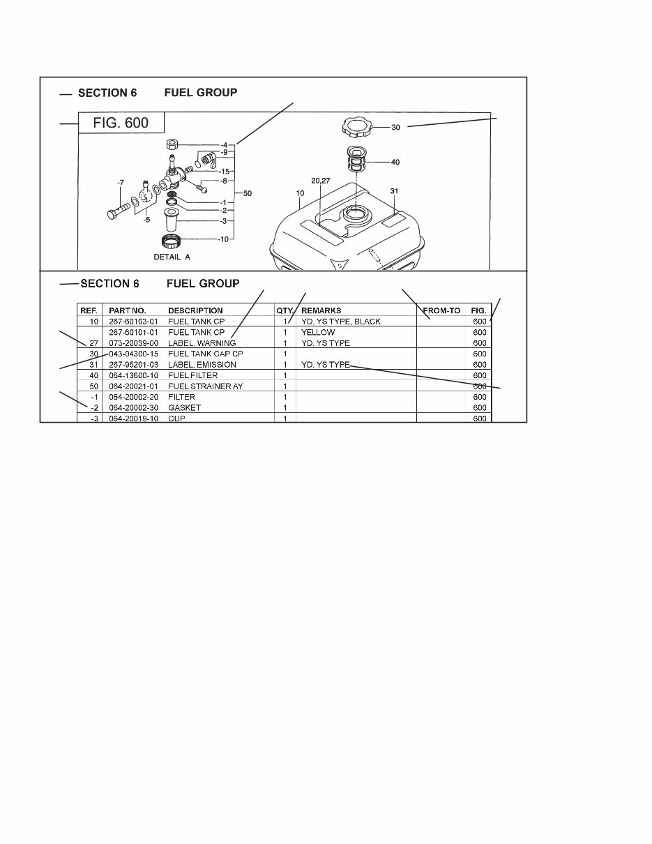
1. SECTION NAME Parts are broadly classified according to their functions.
Refer to the Group Index (table of contents) for respective section name.
2. FIG. No. The FIG. number indexes the reference and part numbers to the illustration. Figure numbers
that vary only in the tens place (i.e..: 700 and 710) are in a group of the same section
(i.e..:Electrical Device Group).
3. REF. No . The Reference number identifies the part illustration with the corresponding part number in the
part list.
4. SUBASSEMBLY SUBASSEMBLY parts of part assembly are listed below the assembly part. The subassembly
part reference number is indicated by the number led by "-" such as "-1", "-2".
5. PART NUMBER It is the number assigned for sales unit. Use the PART No. when making an order.
6. DESCRIPTION It is designation of the part.
7. QTY. Quantity of each part used for each product.
8. REMARKS This gives a distinctive feature and/or a supplementary comment for the type, the specification,
and the part concerned. It also shows part number(s) interchangeable for the part.
9. FROM-TO This section shows the CODE No. to indicate the history of progress in which improved parts
have been introduced in the product. The FROM-TO CODE No. helps to identify PART No.
being employed in the product concerned. See the examples below:
- The part is used in the product irrespective of CODE No.
2101- The part is used in the products with CODE No. of 2101 and after this number.
- 2100 The part is used in the products with CODE No. of 2100 and before this number.
1
2
3
4
1
6 7
9
2
8
3
5
4
EX27 - 5 - 09-08
GROUP INDEX
Group Name Page
CRANKCASE GROUP ............................................................................... 6
CRANKSHAFT GROUP ............................................................................. 8
INTAKE and EXHAUST GROUP.............................................................. 10
GOVERNOR GROUP .............................................................................. 14
COOLING and STARTING GROUP ......................................................... 16
FUEL, LUBRICANT GROUP .................................................................... 18
CARBURETOR GROUP .......................................................................... 26
ELECTRIC DEVICE GROUP .................................................................. 38
ACCESSORY GROUP ............................................................................. 42
SYMBOL DESCRIPTION
AY ........................... ASSEMBLY
CP........................... COMPLETE
EX ........................... EXPORT (from Japan)
FIG.......................... FIGURE
FR. .......................... FRONT
" .............................. INCH
INCL. ...................... INCLUDE
~L............................ LITER
L= ........................... LENGTH (in. mm)
L.H. (LH) ................. LEFT-HAND SIDE
MECH ..................... MECHANICAL
NO (NON) ............... NONE
OPT ......................... OPTIONAL
O.S. ........................ OVER SIZE
SYMBOL DESCRIPTION
P= ........................... PITCH (in mm)
P.T.O. (PTO) ........... POWER TAKE OFF
REF . ........................ REFERENCE
R.H. (RH) ................ RIGHT HAND SIDE
RR. ......................... REAR
STD. ....................... STANDARD
SW .......................... SWITCH
T= ........................... THICKNESS (in mm)
UN .......................... UNIT
U.S.......................... UNDER SIZE
~V ........................... VOLTAGE
~W .......................... WATT
W/ ........................... WITH
W/O ........................ WITHOUT
INDEX OF DESCRIPTION SYMBOLS
EX27 - 6 - 09-08
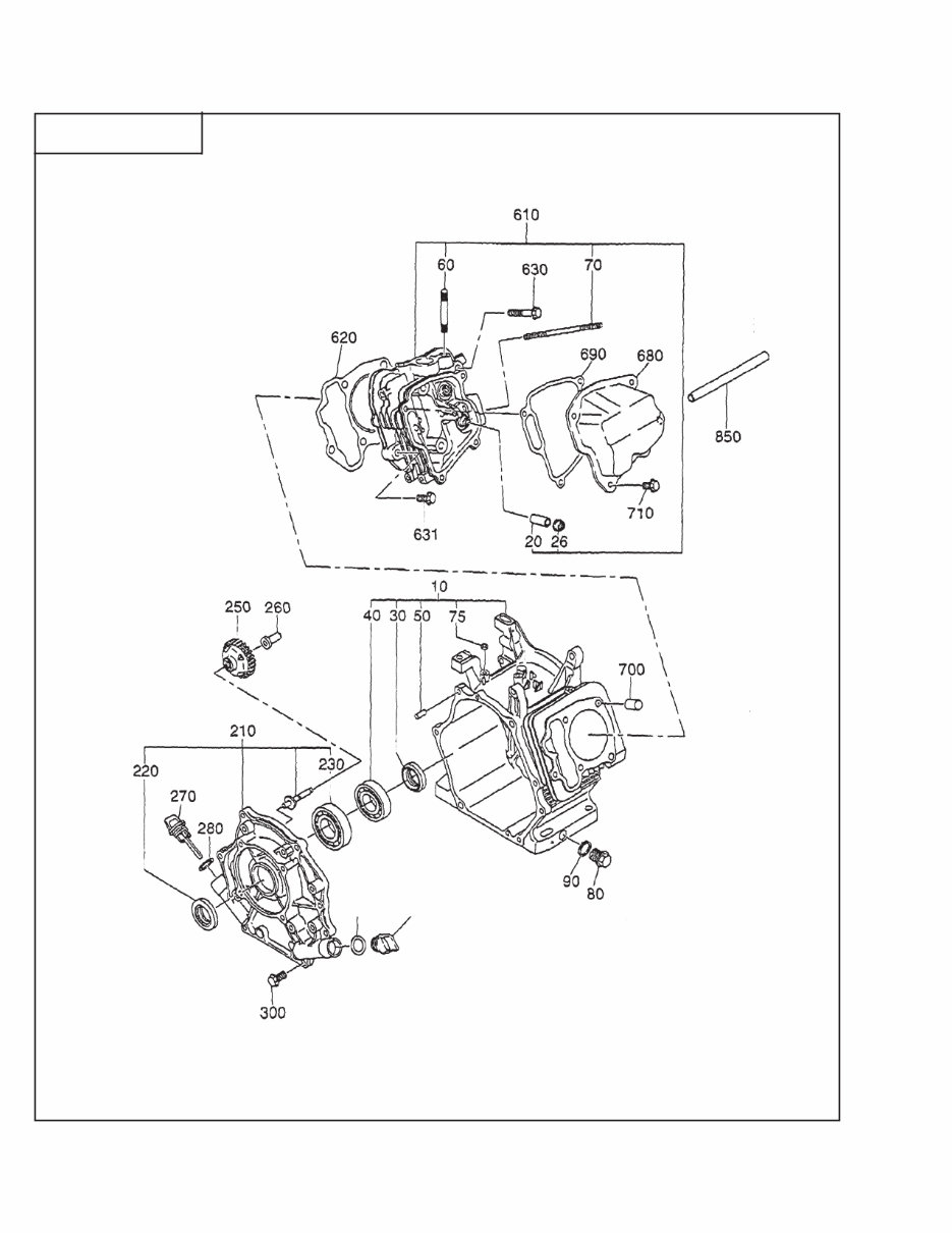
SECTION 1 CRANKCASE GROUP
FIG. 100
270
280

EX27 - 7 - 09-08
SECTION 1 CRANKCASE GROUP
10 279-10101-91 Crankcase Cp 1 Std 6951~ 100
279-10101-81 Crankcase Cp 1 ~6950 100
10 279-10102-91 Crankcase Cp 1 w/ oil sensor 6951~ 100
279-10102-81 Crankcase Cp 1 w/ oil sensor ~6950 100
10 279-10104-51 Crankcase Cp 1 Balancer Shaft 7092~ 100
279-10104-41 Crankcase Cp 1 6951~7901 100
279-10104-31 Crankcase Cp 1 ~6950 100
20 237-14202-03 Valve Guide 2 100
26 277-16010-01 Stem Seal 1 100
30 044-03001-60 Oil Seal 1 100
40 060-03003-41 Ball Bearing 1 100
46 060-01500-11 Ball Bearing 1 7092~ 100
060-01500-10 Ball Bearing 1 ~7091 100
50 277-15011-03 Pipe Knock 2 100
60 010-50802-50 Stud 2 Exhaust 100
70 010-50604-10 Stud 2 Intake 100
75 044-00600-20 Oil Seal 1 100
80 040-11400-30 Plug 1 100
90 021-11400-20 Gasket 1 100
210 279-11002-11 Main Bearing Cover Cp 1 Std 100
210 279-11004-11 Main Bearing Cover Cp 1 Balancer Shaft 100
220 044-03001-60 Oil Seal 1 100
230 060-03003-70 Ball Bearing 1 100
235 060-01500-11 Ball Bearing 1 7092~ 100
060-01500-10 Ball Bearing 1 ~7091 100
250 277-45004-J1 Governor Gear Cp 1 100
260 277-41901-03 Governor Sleeve 1 100
270 279-63601-13 Oil Gauge 2 100
280 021-32000-50 Gasket 1 100
300 001-04083-50 Flange Bolt 7 100
610 279-13001-21 Cylinder Head Cp 1 100
620 279-15001-33 Gasket, head 1 100
630 011-00802-40 Flange Bolt 4 100
631 011-00803-10 Flange Bolt 1 100
680 277-15503-01 Rocker Cover Cp 1 100
690 277-16001-13 Gasket, rocker cover 1 100
700 277-15011-03 Pipe Knock 2 100
710 011-00600-20 Flange Bolt 4 100
960 279-99001-27 Gasket Set 1 100
REF. PART NO. DESCRIPTION QTY. REMARKS FROM-TO FIG.
EX27 - 8 - 09-08
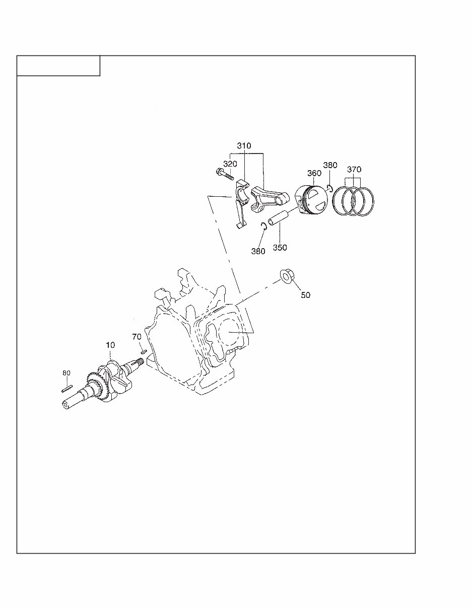
SECTION 2 CRANKSHAFT GROUP
FIG. 200

EX27 - 9 - 09-08
SECTION 2 CRANKSHAFT GROUP
10 279-20901-61 Crankshaft Cp 1 1” key, 3/8 tap - No balancer 200
279-20902-21 Crankshaft CP 1 1" key, 3/8 tap - With balancer 200
279-21001-31 Crankshaft Cp 1 1” Pump 200
279-21201-31 Crankshaft Cp 1 SAE Taper 200
279-20201-61 Crankshaft Cp 1 Metric 25mm key 200
279-20301-41 Crankshaft Cp 1 Metric Pump 25mm key 200
279-20701-41 Crankshaft Cp 1 Metric Taper 200
50 018-01800-10 Flange Nut 1 200
70 032-30300-10 Woodruff Key 1 200
80 207-26001-03 Key 1 200
210 279-24101-13 Balancer Shaft 1 200
310 279-22501-20 Connecting Rod Ay 1 200
320 279-23001-03 Connecting Rod Bolt 2 200
350 279-23301-13 Piston Pin 1 200
360 279-23401-H3 Piston 1 Std 200
279-23403-H3 Piston 1 Oversize 0.25mm 200
279-23404-H3 Piston 1 Oversize 0.50mm 200
370 279-23511-17 Piston Ring Set 1 Std 200
279-23512-17 Piston Ring Set 1 Oversize 0.25mm 200
277-23513-17 Piston Ring Set 1 Oversize 0.50mm 200
370 TBD Piston Ring Set (DE) 1 Std 200
TBD Piston Ring Set (DE) 1 Oversize 0.25mm 200
TBD Piston Ring Set (DE) 1 Oversize 0.50mm 200
380 056-51800-10 Clip 2 200
REF. PART NO. DESCRIPTION QTY. REMARKS FROM-TO FIG.
EX27 - 10 - 09-08
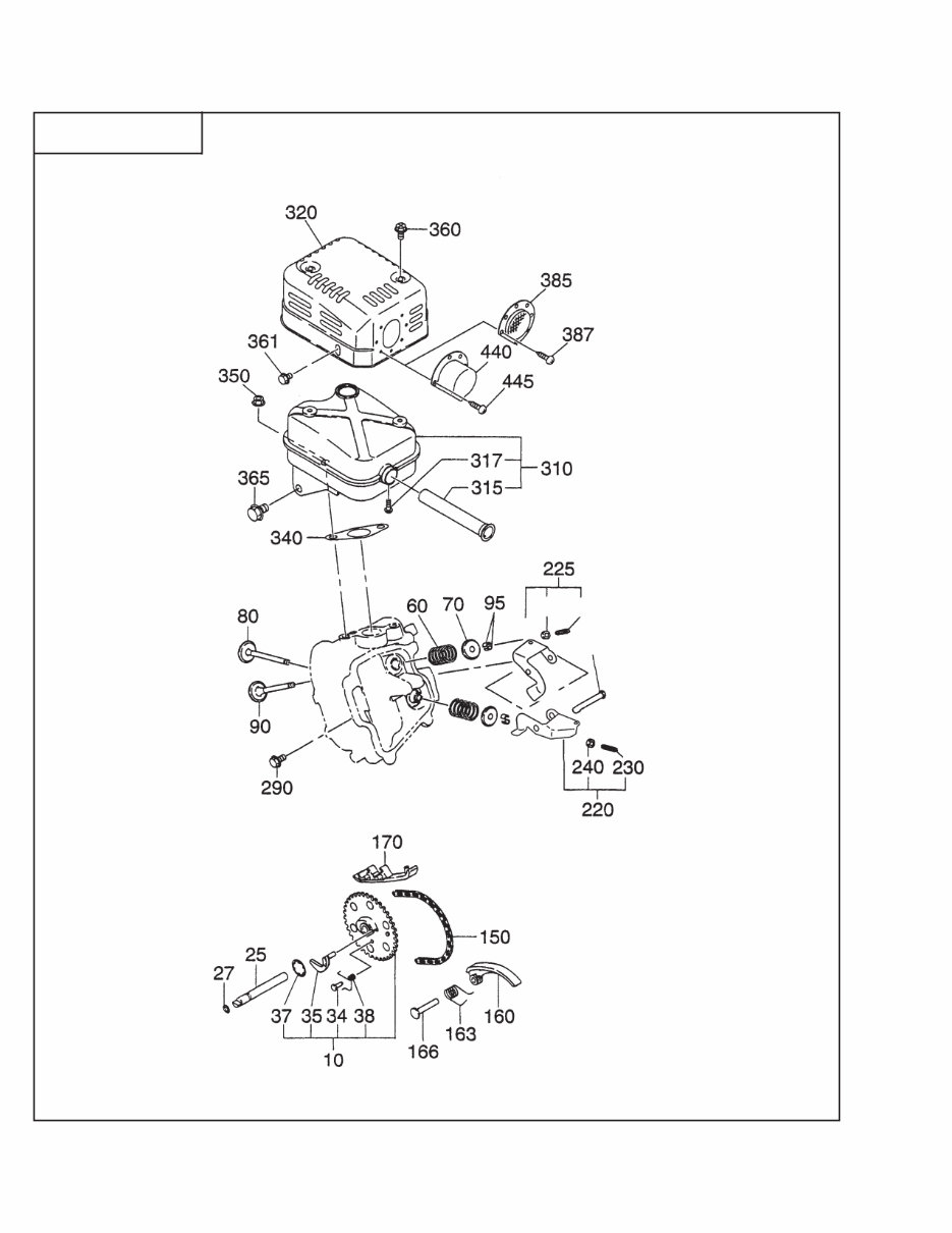
SECTION 3 INTAKE and EXHAUST GROUP - NEW STYLE
FIG. 300
You're Reading a Preview
What's Included?
Fast Download Speeds
Online & Offline Access
Access PDF Contents & Bookmarks
Full Search Facility
Print one or all pages of your manual
$26.99
Viewed 73 Times Today


Secure transaction
What's Included?
Fast Download Speeds
Online & Offline Access
Access PDF Contents & Bookmarks
Full Search Facility
Print one or all pages of your manual
$26.99
Get access to the Robin EX27 parts manual, a comprehensive and fully illustrated parts list with exploded views. This manual serves as a valuable tool for assisting in the disassembly and assembly processes. Whether you're a professional mechanic or a DIY enthusiast, this manual provides essential technical information for maintaining and repairing the Robin EX27 engine.


