Sisudiesel 320, 420, 620, 634 engines Workshop Manual 02 02 Sisu Diesel Inc. FIN–37240 Nokia, Finland Telephone: +358 3 341 7111 E–mail: info.sisudiesel@sisudiesel.com www.sisudiesel.com Diesel Engines, After Sales Telefax: +358 3 341 7333 Sisu Diesel Inc. takes no responsibility for any damages caused because of incorrect information in this manual
Contents 0 --- 0 CONTENTS TO THE USER 0 --- 1 ......................................................................... ENGINE TYPE DESIGNATIONS 0 --- 1 ........................................................... SAFETY INSTRUCTIONS 0 --- 2 ................................................................ ENGINE SPECIFICATION 0 --- 3 ................................................................ LIFTING THE ENGINE 0 --- 3 ................................................................... LOCATION OF THE ENGINE SERIAL NO. 0 --- 3 .................................................. SPECIAL TOOLS 0 --- 4 ....................................................................... TECHNICAL DATA 0 --- 6 ...................................................................... Cylinder block 0 --- 6 ................................................................... Cylinder liner 0 --- 6 ..................................................................... Cylinder head 0 --- 6 .................................................................... Valves, rocker arms and tappets 0 --- 7 .................................................... Camshaft 0 --- 7 ........................................................................ Crankshaft 0 --- 8 ....................................................................... Flywheel 0 --- 8 ........................................................................ Balancing unit 0 --- 9 .................................................................... Timing gears 0 --- 9 ..................................................................... Connecting rod 0 --- 9 .................................................................. Piston, piston rings and pin 0 --- 10 ........................................................ Lubricating system 0 --- 10 ................................................................ Oil pump (320, 420) 0 --- 10 ............................................................... Oil pump (620, 634) 0 --- 11 ............................................................... Coolant pump (320, 420) 0 --- 11 .......................................................... Coolant pump (320, 420 separate ball bearings) 0 --- 11 ....................................... Coolant pump (620, 634) 0 --- 12 .......................................................... Thermostat 0 --- 12 ...................................................................... Turbocharger 0 --- 12 .................................................................... TIGHTENING TORQUES 0 --- 13 ................................................................ CONSTRUCTION 0 --- 14 ....................................................................... General 0 --- 14 ......................................................................... Cylinder block 0 --- 14 ................................................................... Flywheel housing 0 --- 14 ................................................................. Cylinder head 0 --- 15 .................................................................... Valve mechanism 0 --- 15 ................................................................. Crank mechanism 0 --- 15 ................................................................ Timing gears 0 --- 16 ..................................................................... Lubricating system 0 --- 17 ................................................................ Cooling system 0 --- 18 .................................................................. Inlet and exhaust system 0 --- 19 .......................................................... Electronic Engine Management system (EEM) 0 --- 20 ........................................ WORK INSTRUCTIONS 1. CYLINDER BLOCK A. Measuring cylinder liner wear 1 --- 1 .................................................... B. Removing cylinder liner 1 --- 1 ......................................................... C. Checking cylinder block 1 --- 1 ......................................................... D. Changing camshaft bushing 1 --- 1 ..................................................... E. Oversize bushings for camshaft 1 --- 2 .................................................. F. Fitting plug at camshaft rear end 1 --- 3 ................................................. G. Fitting pipe for oil dipstick 1 --- 4 ....................................................... H. Fitting cylinder liner 1 --- 4 ............................................................. 2. FLYWHEEL HOUSING A. Fitting flywheel housing 2 --- 1 ......................................................... B. Changing crankshaft rear oil seal 2 --- 1 ................................................. 3. CYLINDER HEAD A. Removing cylinder head 3 --- 1 ........................................................ B. Removing valves 3 --- 1 ............................................................... C. Checking cylinder head 3 --- 1 ......................................................... D. Changing valve guides 3 --- 2 .......................................................... E. Machining valve seat 3 --- 2 ........................................................... F. Changing valve seat ring 3 --- 3 ........................................................ G. Grinding valves 3 --- 3 ................................................................ H. Fitting valves 3 --- 3 .................................................................. I. Fitting cylinder head 3 --- 4 ............................................................
Contents 0 --- 0 4. VALVE MECHANISM A. Reconditioning valve mechanism 4 --- 1 ................................................. B. Changing camshaft/camshaft gear 4 --- 2 ................................................ C. Adjusting valves 4 --- 3 ............................................................... 5. CRANKSHAFT A. Removing crankshaft 5 --- 1 ........................................................... B. Checking crankshaft 5 --- 1 ............................................................ C. Changing crankshaft gears 5 --- 1 ...................................................... D. Changing crankshaft gear rim (420) 5 --- 2 ............................................... E. Fitting crankshaft 5 --- 2 ............................................................... F. Crankshaft hub piece 5 --- 3 ........................................................... G. Changing crankshaft pulley/vibration damper 5 --- 3 ....................................... H. Checking element of the rubber damper 5 --- 4 ........................................... I. Viscose type vibration damper 5 --- 4 ................................................... 6. CONNECTING RODS AND PISTONS A. Removing pistons together with connecting rods 6 --- 1 .................................... B. Changing connecting rod bearings 6 --- 1 ............................................... C. Checking connecting rod 6 --- 1 ........................................................ D. Changing piston rings 6 --- 3 .......................................................... E. Checking pistons 6 --- 3 .............................................................. F. Fitting piston pin 6 --- 4 ............................................................... G. Fitting piston together with connecting rod 6 --- 4 ......................................... 7. COUNTERBALANCE (420) A. Removing and disassembling counterbalance unit 7 --- 1 .................................. B. Reconditioning counterbalance unit 7 --- 1 ............................................... C. Fitting counterbalance unit 7 --- 1 ...................................................... 8. FLYWHEEL A. Changing starter ring gear on flywheel 8 --- 1 ............................................ B. Fitting flywheel 8 --- 1 ................................................................. 9. TIMING GEAR ASSEMBLY A. Removing timing gear casing 9 --- 1 .................................................... B. Reconditioning idler gear 9 --- 1 ........................................................ C. Fitting timing gear casing 9 --- 2 ........................................................ D. Idler gear with bevelled ball bearings 9 --- 4 .............................................. E. Power take---off 9 --- 5 ................................................................ 10. LUBRICATION SYSTEM A. Reconditioning of oil relief valve for lubricatin oil pressure 10 --- 1 ............................ B. Removing and dismantling lubricating oil pump 10 --- 1 ..................................... C. Assembling and fitting lubricating oil pump 10 --- 2 ......................................... D. Fitting oil sump gasket 10 --- 3 .......................................................... E. Lubricating oil cooler 10 --- 3 ........................................................... F. Piston cooling nozzles (620, 634) 10 --- 3 ................................................. G. Lubrication oil quality requirements 10 --- 4 ............................................... 11. COOLING SYSTEM A. Thermostat 11 --- 1 .................................................................... B. Reconditioning coolant pump (320, 420) 11 --- 1 ........................................... C. Reconditioning coolant pump (320, 420, 620, 634 separate ball bearings) 11 --- 2 ............... D. Coolant pumps with heavy---duty bearings (620, 634) 11 --- 4 ................................ E. Quality requirements of coolant 11 --- 4 .................................................. 12. INLET--- AND EXHAUST SYSTEM A. Checking air cleaner 12 --- 1 ............................................................ B. Checking inlet and exhaust pipes 12 --- 1 ................................................. C. Checking turbocharger 12 --- 1 ......................................................... D. Fitting turbocharger 12 --- 2 ............................................................ 13. FUEL SYSTEM IN---LINE FUEL INJECTION PUMP Technical data 13 --- 1 ................................................................... A. Bleeding fuel system 13 --- 6 ........................................................... B. Bleeding Thermostart system 13 --- 6 .................................................... C. Measuring fuel feed pressure 13 --- 7 .................................................... D. Checking overflow valve 13 --- 7 ........................................................ E. Changing fuel feed pump valves 13 --- 7 ................................................. F. Checking injection timing 13 --- 8 ........................................................ G. Adjusting fuel injection timing 13 --- 9 ....................................................
Contents 0 --- 0 H. Removing fuel injection pump 13 --- 10 .................................................... I. Fitting fuel injection pump 13 --- 10 ....................................................... J. Checking and changing pressure valve 13 --- 12 ............................................ K. Adjusting idling speed 13 --- 12 .......................................................... L. Removing injectors 13 --- 13 ............................................................. M. Inspecting injectors 13 --- 13 ............................................................. N. Reconditioning injectors 13 --- 14 ......................................................... O. Fitting injector in engine 13 --- 15 ......................................................... P. Fitting delivery pipes 13 --- 15 ............................................................ CAV DISTRIBUTOR PUMP Technical data 13 --- 16 ................................................................... A. Dismounting and mounting injection pump 13 --- 17 ........................................ B. Injection pump gear 13 --- 17 ............................................................ C. Bleeding fuel system 13 --- 17 ........................................................... D. Feed pump 13 --- 18 ................................................................... E. Injector 13 --- 18 ....................................................................... STANADYNE DISTRIBUTOR PUMP Technical data 13 --- 19 ................................................................... A. Removing pump 13 --- 24 ............................................................... B. Fitting injection pump and adjusting injection timing 13 --- 24 ................................. C. Bleeding fuel system 13 --- 25 ........................................................... D. Fuel feed pump 13 --- 25 ................................................................ E. Injectors 13 --- 25 ...................................................................... F. Adjusting low idling speed 13 --- 26 ....................................................... G. Bleeding Thermostart system 13 --- 26 .................................................... H. Wiring diagram of electrical advance (CCA) 13 --- 26 ........................................ I. Checking injection timing (dynamic) 13 --- 27 .............................................. Fuel quality requirement 13 --- 29 ........................................................... 14. EQUIPMENT AND FEEDING TABLES 15. ELECTRICAL SYSTEM A. Alternators 15 --- 1 .................................................................... B. Starters 15 --- 4 ....................................................................... C. Electric stop device 15 --- 7 ............................................................. D. Installation of magnetic pick up 15 --- 9 ................................................... E. Temperature sensor 15 --- 9 ............................................................ 16. OPTIONAL EQUIPMENT A. Compressor (Bendix) 16 --- 1 ........................................................... B. Compressor (Knorr) 16 --- 2 ............................................................ C. Industrial clutch (A.P. Borg & Beck) 16 --- 3 ...............................................
420 DSRIEL Application A = vehicle engine G= generating set engine L = combine harvester engine M= marine engine P = pump set engine Equipped with intercooler A = air to air I = air to water Rotary fuel injection pump (B, if equipped with Bosch P---type injection pump) Turbocharged engine (W, if equipped with by---pass turbo) Basic type (E, if equipped with electronic engine control) Number of cylinders (3, 4 or 6) E =emission tested engine (certified) for off---road C= emission tested engine (certified) for on---road To the User 0 --- 1 TO THE USER This Workshop Manual is intended to facilitate workshop operations and repair work. 320, 420, 620 and 634---engines are mainly the same in construction, so the same repair instructions usually apply to different engine types. The differences between the various engine types which affect repair work have been mentioned in technical data and repair instructions. All measurements are in millimetres and valid when the temperature of the parts is +20˚C, unless other- wise stated. Before starting the repair work read the safety instructions in the beginning of this book. Make sure that you have all necessary tools, parts and accessories at your disposal. The special tools mentioned in the work instructions are not all essential, but they speed up and facilitate the work and contribute to successful execution of work. An engine which has undergone repairs must be run in just like a new one. Should the engine require measures not described in this manual, please consult your local agent or the Service Department of Sisu Diesel Inc., Linnavuori, Finland. To facilitate consulting, find out the following facts about the engine before contacting us: --- enginetype --- enginenumber --- application or equipment --- hours operated or kilometres driven. In this Workshop Manual the regular service procedure is not handled as this is explained in the 20/34---series Operator’s Manual. As Sisu Diesel Inc. is continuously developing the products, all rights are reserved without separate notice to change the adjust- ments, accessories and service--- and repair procedure. ENGINE TYPE DESIGNATIONS
Safety Instructions 0 --- 2 SAFETY INSTRUCTIONS In the service--- and repair work of the engine there is al- ways the possibility of injury. Before starting the work read and understand the following safety instructions and remarks! Do not start a repair work that you do not fully handle. Make sure that the place of the repair and the surround- ing gives the possibility for safe working. Always be sure of the cleanness and the good order of the repairing place. Do not use faulty or otherwise useless tools. Remove all finger rings, chains and watch before start- ing work. Use up---todate protection equipment when you work. For example eye protection as working with compressed air for cleaning, grinding, hammering or other work. Use lifting device for lifting and transporting heavy (over 20 kg) pieces. make sure of good condition of lifting hooks and chains. The lifting ears on the engine must not be applied by side forces when lifting. Never work under an engine that is left handling under a lifting device or lifted up by a jack. Always use strong sup- ports before starting the work. Use only genuine Sisudiesel spare parts. Start the engine only by using the starting switch in the cabin. Do not start an engine if the protection covers are re- moved. NOTE! The fan is difficult to see as the engine is run- ning! Make sure that wide clothes or long hear is not caught in the rotating parts of the engine. If you start the engine indoors, be sure you have proper ventilation. Never use aerosol type of starting aid while operating the thermostart device (risk for explosion). When you are operating the engine or working near it, use hearing protectors to avoid noise injuries. Stop the engine always before service--- or repair work. Avoid touching the exhaust manifold, turbocharger and the other hot parts of the engine. Open the radiator cap with care when the engine is hot as the cooling system is pressurised. The cooling liquid and lubrication oil of a hot engine causes injuries when touching the skin. Open fire, smoking and sparks should not be allowed near the fuel system and batteries. (Specially when loading batteries, explosive.) Always disconnect the minus (---) wire of the battery when doing service or repair of the electric system. At temperatures on excess of 300˚C, e.g. if the engine is burnt by a fire, the viton seals of the engine (e.g. the under- most o---ring of the oil pressure regulating valve) produce very highly corrosive hydrofluoric acid. Do not touch with bare hands, viton seals subjected to abnormally high tempera- tures. Always use neoprene rubber or heavy duty gloves and safety glasses when decontaminating. Wash the seals and the contaminated area with a 10% calcium hydroxide or other alkali solution. Put all removed material in sealed plastic bags and deliver them to the point stated by the Authorities con- cerned. NOTE! Never destroy viton---seals by burning! When checking fuel injectors do not let the jet of high pressure fuel contact your skin. The fuel penetrates the skin causing severe injuries. Contact your doctor immediately! The fuel, lubricating oil and coolant cause irritation in skin contact for long time. Avoid unnecessary idling of the engine. Do not let oil and other liquids drop into the soil when servicing the engine. All the gaskets of the engine are of non---asbestos ma- terial. Be careful when washing the engine with a high pres- sure washing machine. Do not use high pressure to wash e.g. the electric and fuel equipment or the radiator because they can easily be damaged.
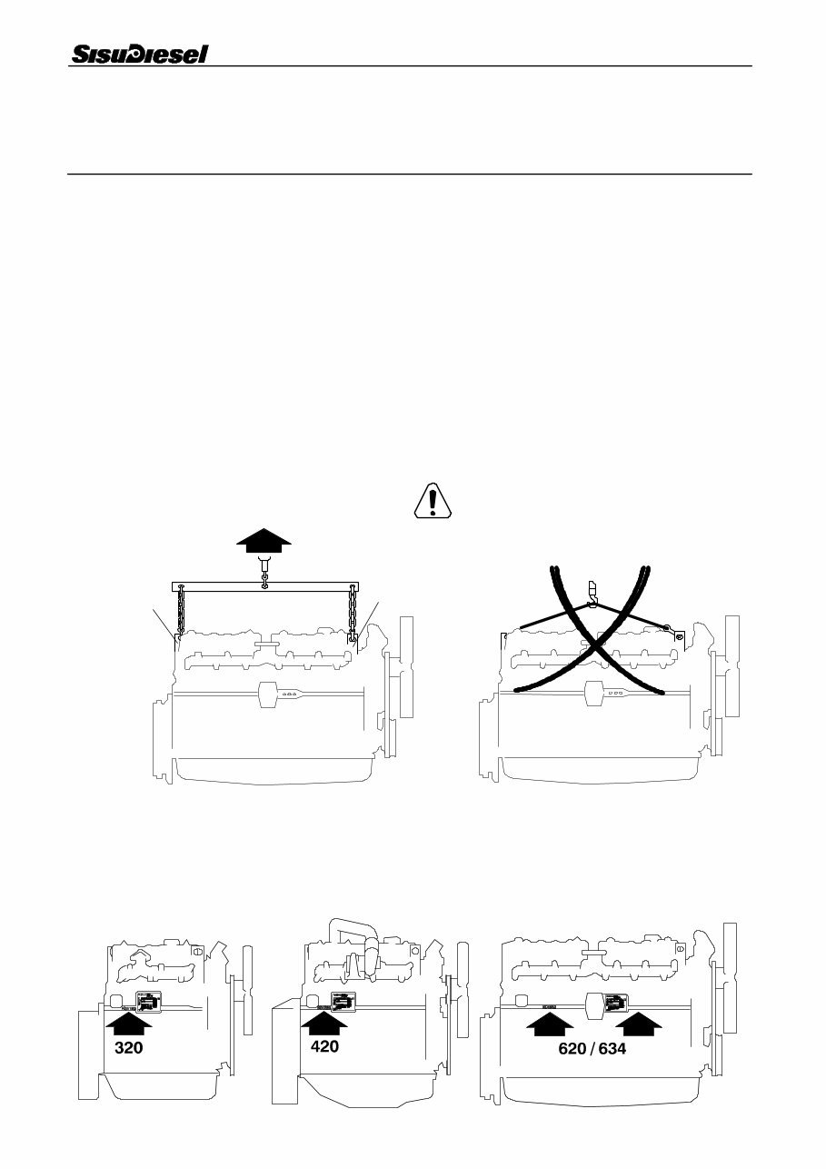
Engine Specifications 0 --- 3 ENGINE SPECIFICATIONS Engine type 320D 320DS 420D 420DS 420DW 420DWI 620D 620DS 634DS Number of cylinders 3 3 4 4 4 4 6 6 6 Displacement (dm 3 ) 3,3 3,3 4,4 4,4 4,4 4,4 6,6 6,6 7,4 Cylinder bore (mm) 108 108 108 108 108 108 108 108 108 Stroke (mm) 120 120 120 120 120 120 120 120 134 Compression ratio 16,5/18,5:1 Combustion direct injection Firing order 1 --- 2 --- 3 1 --- 2 --- 4 --- 3 1 --- 5 --- 3 --- 6 --- 2 --- 4 Compression pressure bar 1 24 Weight kg 2 275 280 335 340 340 345 500 510 515 Direction of rotation from the engine front clockwise 1 ) Minimum value at operating temperature and starting revs. Max permitted difference between cylinders 3,0 bar. 2 ) Without flywheel and electrical equipment. LIFTING THE ENGINE Safe lifting of the engine is done with a lifting device where the lifting force effects the lifting ears vertically. A = Engine lifting ears Engine weight: see Engine Specifications LOCATION OF THE ENGINE SERIAL NO. 20 --- 1 20 --- 4 A A 20 --- 5
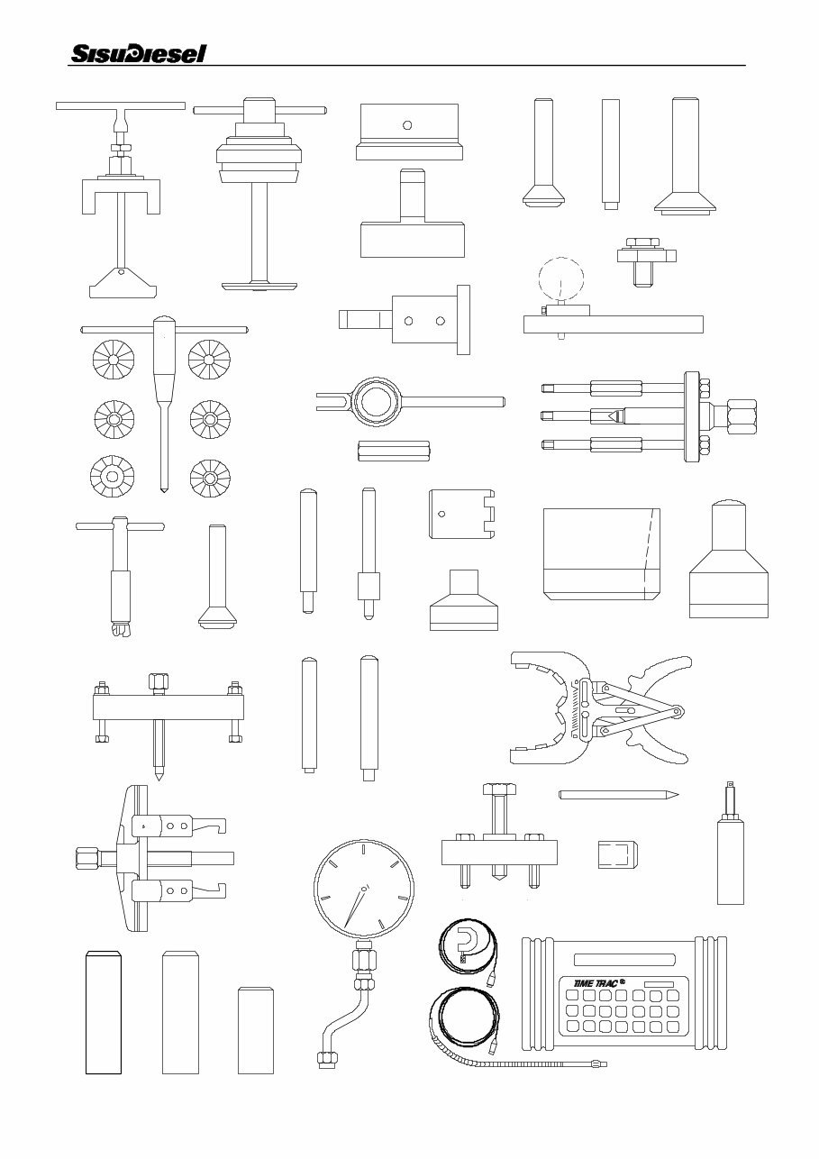
Special Tools 0 --- 4 SPECIAL TOOLS Order no Description 1 9051 73100 Puller for cylinder liner 2 9101 65600 Milling cutter for cylinder liner seat 9045 87600 Spare cutting blade for milling cutter 3 9052 46400 Centring tool for flywheel housing 4 9052 46300 Drift for fitting rear crankshaft seal 5 9030 15200 Drift for fitting front crankshaft seal 6 9052 46620 Drift for 40 mm cup plug 7 9052 46650 Drift for 16 mm cup plug 8 9025 87400 Drift for fitting camshaft cup plug 9 9101 66300 Press tool for cylinder liner 10 9025 79200 Holder for dial gauge 11 9101 66100 T---handle for valve seat milling cutter 12 9101 71100 Milling cutter for facing exhaust valve seat 13 9101 65502 Milling cutter for exhaust valve seat 14 9101 65503 Inner milling cutter for exhaust valve seat 15 9101 75800 Milling cutter for facing inlet valve seat 16 9101 65505 Milling cutter for inlet valve seat 17 9101 65506 Inner milling cutter for inlet valve seat 18 9101 66200 Lever for compressing valve spring 19 9052 47200 Counter nut for lever above 20 9101 66000 Milling tool for injector seat 21 9052 46660 Drift for 36 mm cup plug 22 9101 65800 Drift for removing valve guide 23 9101 65900 Drift for fitting valve guide 24 9024 55800 Spanner for crankshaft nut, 634---engines (620/MF/Steyr---tractors) 25 9101 65700 Spanner for crankshaft nut 26 9052 48800 Puller for crankshaft gears 27 9020 01100 Conical sleeve for fitting pistons 28 9052 46900 Piston ring pliers 29 9025 98900 Drift for fitting dust cover, crankshaft front seal 30 9025 98800 Drift for fitting tension pin in timing gear casing 31 9025 98700 Drift for fitting tension pins in timing gear casing and flywheel housing 32 9101 93200 Coolant pump impeller extractor 620, 634 33 9104 27700 Coolant pump impeller extractor 320, 420 34 9050 40200 Fitting tool for coolant pump axial seal (seal 8353 31202) 35 9051 79300 Fitting tool for coolant pump axial seal (seal 8353 39425) 36 9051 64900 Fitting tool for coolant pump shaft 320, 420 37 9052 47800 Pressure valve testing gauge 38 9052 48900 Extractor for injection pump gear 39 9025 99100 Injection timing check pin (320, 420, 620, 634/Valtra Valmet---tractors) 40 8366 62022 Electronic timing kit 41 9025 99000 Control rod locking bush 42 9051 71300 Extractor for injector
The Sisu 320/420/620/634 Series Diesel Engine Service Shop Repair Manual provides detailed servicing instructions for professional mechanics and DIY enthusiasts. This comprehensive manual offers step-by-step information on repair, servicing, preventative maintenance, and troubleshooting procedures for Sisu diesel engines. It features photos, illustrations, and detailed instructions to guide you through the entire repair process, making it an indispensable source of maintenance and repair information. The manual covers general information, care and safety, routine maintenance, systems description, fault finding, test procedures, fuel system, cooling system, lubrication system, electrical system, induction and exhaust system, and base engine.
Key Features:
Instant access with no waiting time
Easy navigation for quick identification of service repair procedures
Detailed illustrations, exploded diagrams, drawings, and photos
Printable format with 114 pages in English
File Format: PDF
Covers the following Sisu Models:
320
420
620
634
After purchasing the service manual, you can instantly view and print it whenever needed. This manual is designed to help you better understand, care for, and service your Sisu 320/420/620/634 Series Diesel Engine, ultimately lowering the repair and maintenance costs.
Recently Viewed
5,521,897Happy Clients
2,594,462eManuals
1,120,453Trusted Sellers
15Years in Business
Price:
Actual Price:
Sisu Service 320/420/620/634 Series Diesel Engine Manual Workshop Service Repair Manual