

http://BestManuals.net
Best.Manuals@yahoo.com
Introduction
This manuai is written specifically for skilled service
personnel and it is therefore assumed that the
warkshop safety and repair procedures generally
accepted by the motor trade are appreciated,
understood, and carried wt
Information relating to any subsequent
modification will be circulated by the issue of amended
or addition+ pages.
Each chapter incorporates an issue record shoet
Reference must be made to these sheets when
determining either the current issue date for a
particular page, or the number of pages contained
within a chapter/section.
Throughout the rnanuat reference is made to the
right-hand and left-hand side of the car, this is
determined when sitting in the driver's scat.
In order to identify the two banks of engine
cylinders, it should be noted that 'K bank of cylinders
is on the right-hand side and '8' bank on the left-hand
side when viewed from the driveis seat
Se~ce personnel at Rolls-Rgree Motor Cars
Limited are always prepared to aanswr queries or give
advice on individual servicing problems. When making
an enquiry it is essential that the full vehicle
identification number (VINJ is quoted.
important
When obtaining information for a particular model
always refer to the appropriate Chapter and/or Section
contents page.
9/89 TSD 4737
Contents
Uupter A
General information
Chapter B
Fuel injection -ern
Chapter C
Fuel system
Chapter D
Turbocharging system
Chapter E
Ignition.system
(For details of the ignition system fitted to l989
rndl year turbcharged cars. refer to Chapter B.
Seaion 54, K-Moronic)
Chapter F
Exhaust emission control system
Chaptw G
Fuel evaporative emission control system
Chapter U
Crankcase emission con! rol system
Chapter J
Air intake system
Chapter K
Throttle linkage
Chapter L
Special toque tightening figures
Chapter M
Workshop took
Chapter N
-Running changes
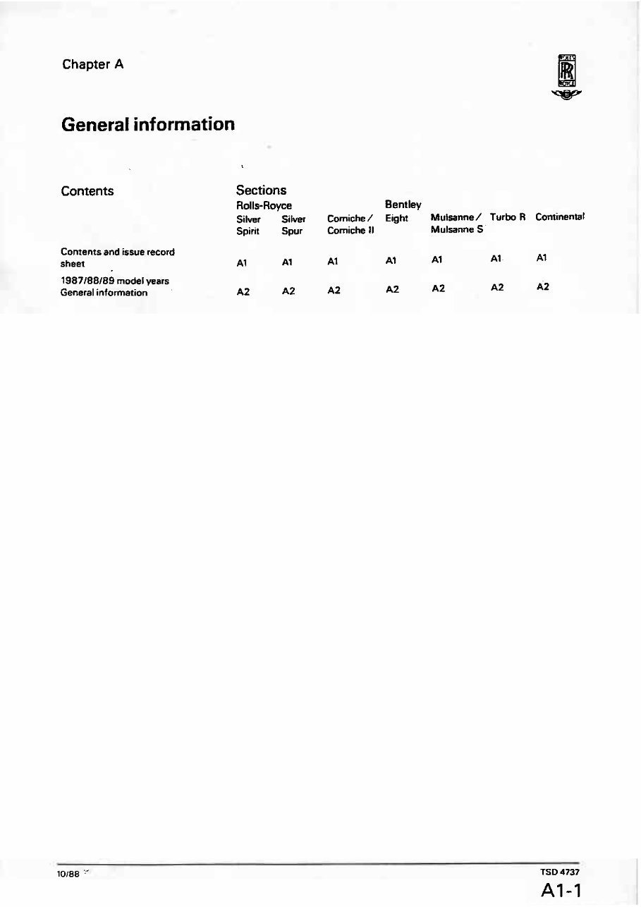
Chapter A
General information
Contents
Contents and issue record
sheet
1987188109 model years
General information
Sections
Rolls-Royce Bentley
Silver Sihrer Comiche / Eight Muisanne/ Turbo R Continental
Spirit Spur Comiche II Mulranne S
AI A1 Al A9 A1 Al. At
10188 " TSD 4737
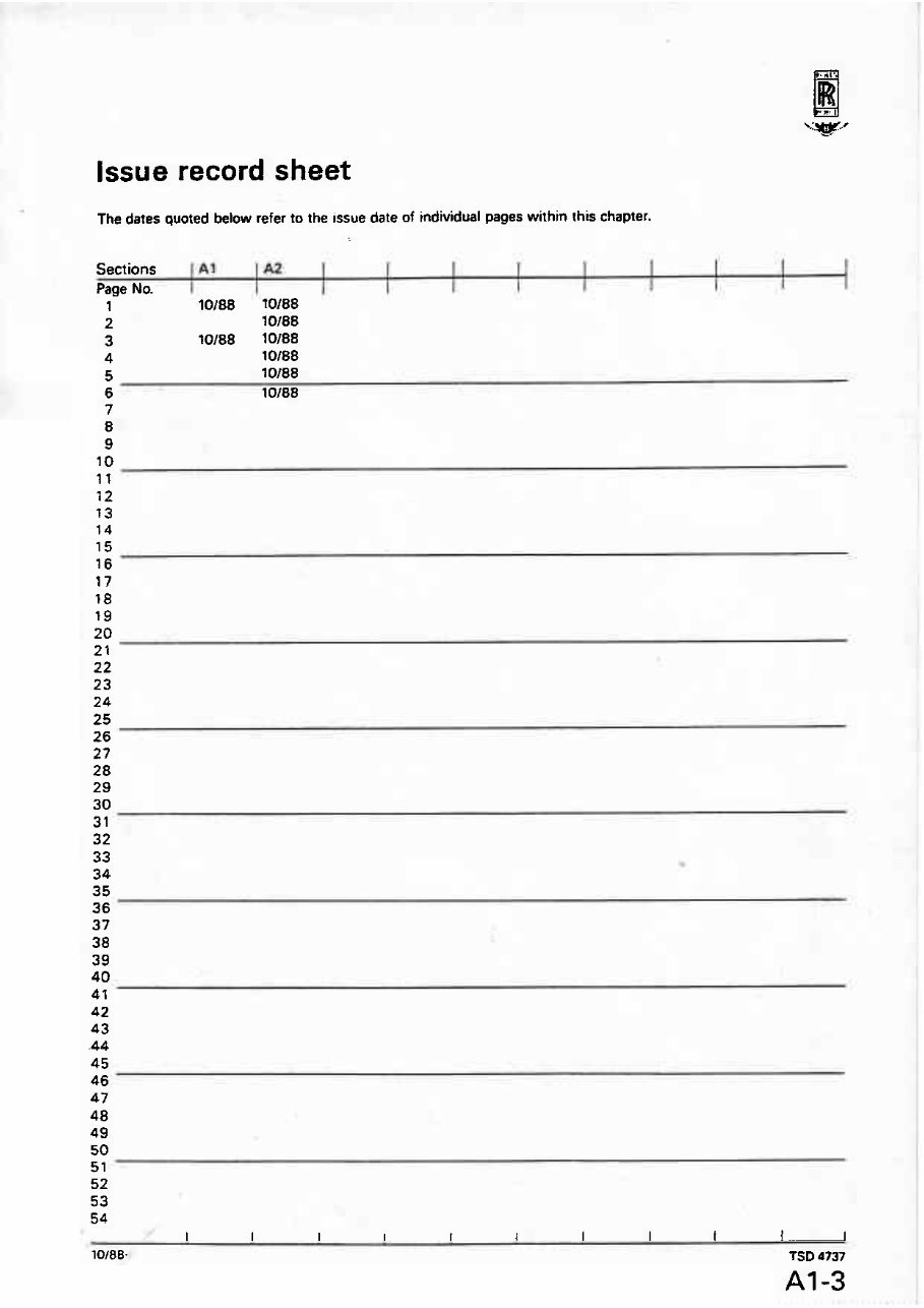
Issue record sheet
The dates quoted below refer to the issue date of individual pages within this chapter.
Sections 1 &l 1 ~2 1 I I T 1 1 I 1
Page No. I I I I I
1 10188 10188
2 l0188
3 10188 10188
4 10188
5
lOl88
6 10188

Section A2
General information
Heahh risk
Engine oils
Prolongedand repeated contact with mineral oil will
result in the removal of natural fatsfrom the skin.
leading t o dryness. irritation, and dermatitis. In addition.
used engine oil contains potentially harmful
contaminants which may cause skin cancer. Adequate
means of skin protection and washing facilities should
be provided.
Health protection precautions
1. Avoid prolonged and repeated contsct with oils,
particularly used engine oils.
2. Wear protective clothing, including impervious
gloves where practicabte.
3. Do not put oily rags in pockets.
4. Avoid contaminating clothes, particularly
underpants. with oil.
5. Overalls must be cleaned regularly. Discard
unwashable clothing and oil impregnated footwear.
6. First aid treatment should be obtained immediately
far open cuts and wounds.
7. Use barrier creams. applying before each work
period. to help the removal of oil from the skin.
8. Wash with soap and water to ensure all oil is
rernwed (skin cleansers and nail brushes will help).
Preparations containing lanolin replace the natural skin
oils which have been remwed.
9. Do not use fuel, kerosine, diesel fuel, gas oil,
thinners, or solvents for washing skin.
10. If skin disorders develop. obtain medical advice
11. Where practicable, dsgrease components prior to
handling.
12. Where them is a risk of eye comaet. eye protection
should be worn, for example, chemical goggles or face
shields; in addition an eye-wash facility should be
provided.
See atso UK Health and Safety Executive
Cautionary Notice SHW 397 'Effects ofMineral Oil on
the Skin'.
Environmental protection precautions
tt is illegal to pour used oil onto the ground, down
sewers or drains. or into water courses.
The burning of used engine oil in small space
heaters or boilers is not recommended unless emission
control equipment is fitted. In cases of doubt check
with the Local Authority.
Dispose of used oil through authorized waste
disposal contractors t o licensed waste disposal sites, or
to the waste oil reclamation trade ff in doubt, contact
the Local Authority for adviceor disposal facilities.
Exhaust gases
The exhaust gases contain carbon monoxide (CO),
which is odourless and invisible but very poisonous.
Operating the air conditioning system in 8 confined
space incmases the danger of these Bases entering the
car.
ideally. engines should be tun in the open where the
exhaust gases can discharge into the atmosphere
However. when running engines within an enclosed
working area. the exhaust gases must always be
removed safely.
Refer to further text withirrthis manual regarding
the use of exhaust gas extraction hoses and equipment.
Fuel
Fuel may contain up to 5% of benzene as an anti-knock
additive Benzene is extremely injurious t o health {being
carcinogenic) therefom all cantact should be kspt tb an
absolute minimum, particularly inhalation.
Fuel has a sufficiently high vapour pressurn to allow
a hazardous build-up of vapour in poorly ventilated
areas. Therefore. any work should be carried out in a
well ventilated area.
Fuel vapour is an irritant t o the eyes and lungs, and
if high concentrations are inhaled it may cause nausea,
headache, and depression.
Fuel liquid is an irritant t o the eyes and skin and may
cause dermatitis following prolonged or repeated
contact.
When it becomes necessary to carry out work
involving the risk of contact with fuel, particularly for
prolonged periods, it is advisable t o wear protective
clothing including safety goggles, gloves, and aprons.
If there is contact with fuel the following
emergency treatment is advised.
Ingestion Iswallowing)
Do not induce vomiting. Give thepntient milk to drink (if
none is availabte water can be given). The main hazard
after swallowing fuel is that some of the liquid may get
into the lungs. Send the patient to hospital immediately.
Eyes
Wash with a good supply of clean water for at least 10
minutes.
Skin contact
Immediately drench the affected parts of the skin with
water. Removecontaminated clothing and then wash all
contaminated skin with soap and water.
Inhalation {breathing in vapour)
Move the patient into the fresh air. Keep the patient
warm and at rest. If there is loss of consciousness give
artificial respiration. Send the patient to hospital.
High vohage Isvets
Dangerously high vohsge levels are present in an
electronic ignition system. These levels are not only
TSD 4737
A2-1
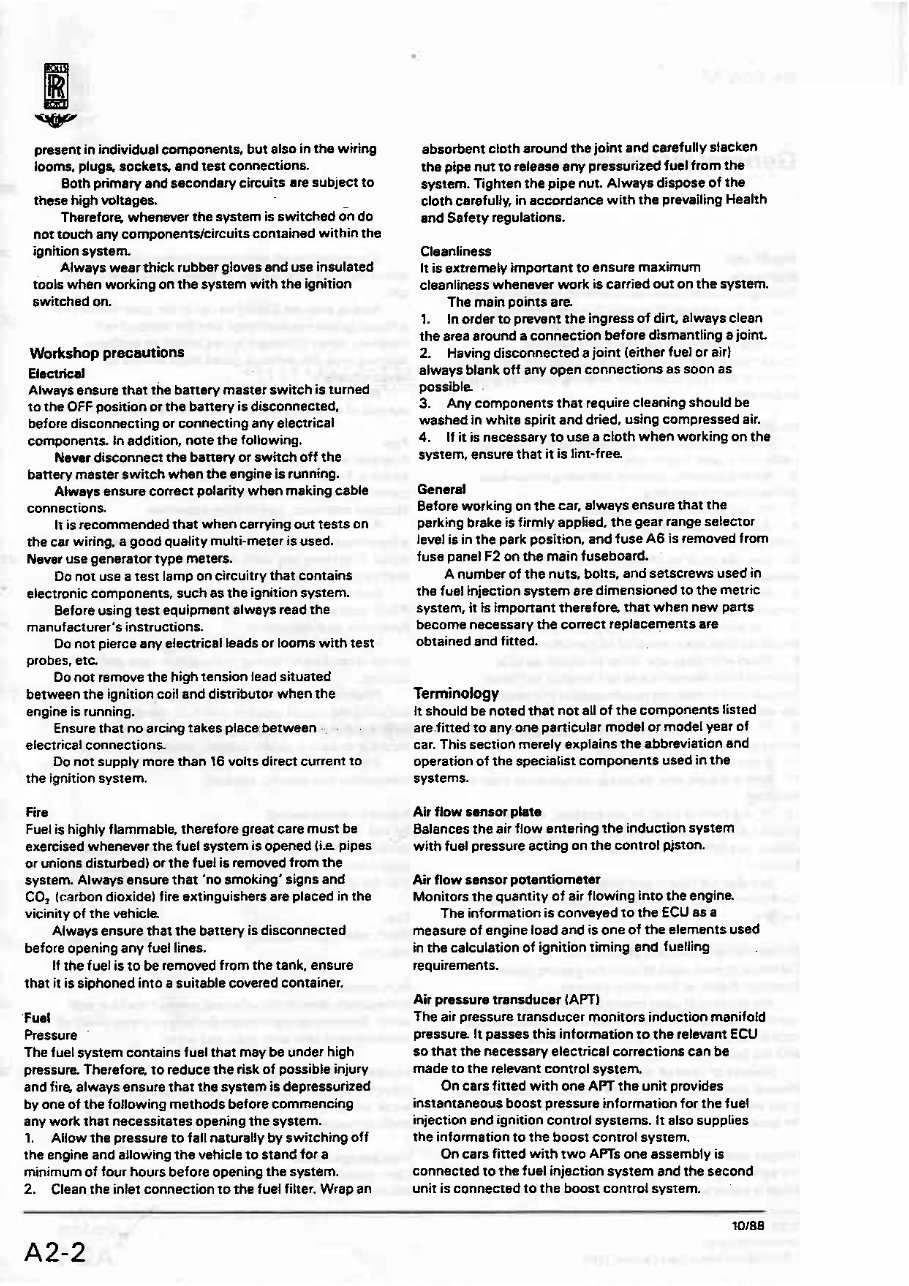
present i n individual components, but also in the wiring
looms, plug& sacketr and test connections.
Both primaty and secondary circuits are subject to
these high wltages.
Therefore. whenever the system is switched &? do
not touch any cornponents/circuits contained within the
ignition system
Always wear thick rubber glows and use insulated
tools when working on the system with the ignition
switched on.
Workshop precsutions
Electrical
Always ensure that the battery master switch is turned
to the OFF position or the battery is disconnected,
before disconnecting or connecting any eteetrical
components. In addition, note the following.
Never disconnect the battery or switch off the
battery master switch when the engine is running.
Always ensure correct polarity when making cable
connections.
Ir is recommendedthat when carrying out tests on
the car wiring. a good quality mufti-meter is used.
Never use generator type meters.
Do not use a test lamp on circuitry that contains
electronic components, such as the ignition system.
Before using test equipment always read the
manufacturer's instructions.
Do not pierce any electricai leads or tooms with test
probes. etc.
Do not remove the high tension lead situated
between the ignition coil and distributor when the
engine is running.
Ensure that no arcing takes place: herween -.. - .
electrical connections
Do not supply more than 16 volts direct current to
the ignition system.
Fire
Fuel is highly flammable, therefore great care must be
exercised whenever 1 he fuel system is opened IiAL pipes
or unions disturbed) or the fuel is removed from the
system. Always ensure that 'no smoking' signs and
CO, (carbon dioxide) fire extinguishers are placed in the
vicinity of the vehicle.
Always ensure that the battery is disconnected
before opening any fuel lines.
If the fuel is to be removed from the tank, ensure
that it is siphoned into a suitable covered container.
'Fuel
Pressure
The fuel system contains fuel that may be under high
pressure. Therefore, to reduce the risk of possible injury
and fire, always ensure rhat the system is depressurized
by one of the foIlowing methods before commencing
any work that necessitates opening the system.
1. Allow the pressureto fall naturally by switching off
the engine and allowing the vehicle to stand for a
minimum of four hours before opening the system.
2. Clean the inlet connection to the fuel fitter. Wrap an
absorbent cloth around the joint and carefully stacken
the pipe nut to release any pressurized fuel from the
system. Tighten the pipe nut. Always dispose of the
cloth carefully, in accordance with the prevailing Health
and Safety regulations.
Cleanliness
It is extremely important to ensure maximum
cleanliness whenever work is carried out on the system.
The main points are.
1. In order t o prevent the ingress of dirt, always clean
the area around a connection before dismantling a joint.
2. Having disconnected a joint (either fuel or air1
always blank off any open connections as soon as
possible -
3. Any components that require cleaning should be
washed in white spirit and dried, using compressed air.
4. If it is necessary t o use a cloth when working on the
system, ensure that it is lint-free.
Generd
Before working on the ear. always ensure that the
parking brake is firmly applied. the gear range selector
level is in the park position, and fwe A6 is removed from
fuse panel F2 on the main fuseboard.
A number of the nuts. bolts, and setscrews used in
the fuel injection system are dimensioned to the metric
system, it is important therefore, that when new parts
become necessary the correct replacements are
obtained and fitted.
Terminology
It should be noted that not all of the components listed
are.fiaed to any.one particular model or model year of
car. This section merely explains the abbreviation and
operation of the specialist components used in the
systems.
Air flow sansor plate
Balances the air flow entering the induction system
with fuel pressure acting an the control pjston.
Air flow sensor potentiorneter
Monitors the quantity of ait flowing into the engine
The information is conveyed ro the ECU as a
measure of engine load and is one of the elements used
in the calculation of ignition timing and fuelling
requirements.
Air pressure transducer {APT)
The air pressure transducer monitors induction manifold
pressura It passes this information to the relevant ECU
so that the necessary electrical corrections can be
made t o the retevant control system.
On cars fined with one APT the unit provides
instantaneous boast pressure information for the fuel
injection end ignition control systems. It also suppties
the information to the boost control system.
On cars fitted with TWO APTs one assembly is
connected to the fuel injection system and the second
unit is connected to the boost control system.
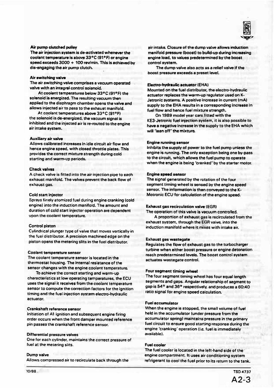
Air pump clutched pufley
The air injection system is de-activated whenever the
coolant tcrmprature is aboy 33'C (91°F 1 w engine
speed exceeds 3000 + l00 wlmin. This is achieved by
dis-engaging the air pump clutch.
Air swkching vmlw
The air switching value comprises a vacuum operated
valve with m integml control solenoid.
At coolant temperatures belaw 33OC 19t°F) the
solenoid b energized The resulting vacuum then
applied to the diaphragm chamber opens the valve and
allaws injected air to PISS to the exhaust manifold.
At coolant temperatures above 33OC {91QFl
the solenoid is de-enefgued, the vacuum signal is
inhibited and the injected air is re-routed t o the engine
air intake system.
Auxairy air valve
Allows ealibreted increases in idle circuit air flow and
hence engine speed, with closed throttle plates. 1 his
provides the correct mixture strength during cold
starting and warm-up periods.
Check valves
A check valve is fitted into the air injeetion pipe to each
exhaust manifold. The valves prevent the back flow of
exhaust gas.
Cold start injector
Sprays finely atomized fuel during engine cranking (cold
engine) into the induction manifold. The amount and
duration of cold start injector operation a* dependent
upon the coolant ternpenturn
Control piston
Cylindrical plunger type of'&= that moves vertically in
the fuel distributor. A precision machined edge on the
piston opens the metering slits in the fuel distributor.
Coolant temperature sensor
The coolant temperature sensor is located in the
thermostat housing. The internal resistance of the
sensor changes with the engine coolant temperature.
To achieve the correct starting and warm-up
characteristics at low operating temperatures, the ECU
uses the signal it receives from the coolant temperature
sensor to compute the correction factors for the ignition
timing and the fuel injection system electro-hydraulic
actuator.
.Crankshaft refarence sensor
Initiation of A1 ignition and subsequent engine firing
order occurs when The from damper mounted reference
pin passes the crankshaft reference sensor.
Differential pressure vaives
One for each cylinder. maintains the correct pressure of
fuel at the metering slits.
Dump valve
Allows compressed air to recirculate back through the
air intake Closum of the dump valve allows induction
manifold presswe l boost1 to build-up during increasing
engine load, tovalues predetermined by the boost
conmh system.
The dump valve also acts as a relief valve /f the
boost presswe exceeds a preset level.
Eleetro-hydraulic actuator (EHAI
Mounted on the fuet distributor. the electro-hydraulic.
actuator replaces the warm-up regulator used on K-
Jetronicsystema A positive increase in cunem (mA)
supply to the EHA results in a corresponding increase in
fuel flow and hence fuel mixture strength.
On 1989 model year cars-fitted with the
KE3-Settonicfuel injection system, it is also possible t o
have a negative increase in thesupply to the €HA which
will 'Iran off* the mixture
Engine ~nning sensor
Inhibits thesupply of power to the fuel pump unless the
engine is running. The only exception being one by-pass
to the circuit. which allows the fuel pump to operate
when the engine is being 'cranked' by the starter motor.
Engine sped sensor
The signal generated by the rotation of the four
segment timing wheel is sensed by the engine speed
sensor. The information is then conveyed to the K-
Motronic ECU for calculstion of the engine speed.
Exhaust gas recirculation valw EGR)
The operation of this valve is vacuum controlled.
A proponion of exhaust gas is recirculated from the
exhaust svstem, through the EGR value, into the
induction manifotd where it mixes with intake air.
Exhaust gas wastegate
Regulates the flow of exhaust gas to the turbocharger
turbine when either boost pressure or engine detonation
reach predetermined Iwels. The boost contr01 system
actuates wastegate control.
Four segmant timing wheel
The four segment timing wheel has four equal length
segments and gaps. Angular felationship of segment t o
gap is 54 and 36 respectively, ant3 produces a 60:40
ratio signal for engine speed cakulation.
Fuel aceumutatar
When the engine is stopped. the small volume of fuel
held in the accumulator (under pressure from the
accumulator spring) maintains pressure in the primary
fuel circuit to ensure good starting response during the
engine 'cranking' operation {i.e. fuel is immediately
. -
availabbl.
. ..
.. .
.. . .
, ,
Fuel cooler
The fuel cooler is located in the left-hand side of the..
engine compartment. It uses air conditioning system
refrigerant to cool the fuel prior to its return to the tank.
Fud distributor
Apportions the fuel equally ta he injectors adjacent to
each en~ine cylinder.
Fuel pressure rngulator
Maintains a eansrant primary circuit fuel pressura
When the engine is stopped. the fuel pressure regulator
allows the system pressure to drop rapidly t o a value
preset by the fuel accumularor (ia. just below the
injeftor valve operating pressure). It also seals the
return tine from the lower chambers of the differential
pressure value.
Haatad ox ygsn sensor
Measures the oxygen content (which is directly related
to the aidfuel ratio) in the exhaust gas and by means of
an electrical signal transmits the information to the
electronic control unit.
Idle speed actuator
The idle speed actuator contains a stepping motor, the
armature of which is connected to a rotating slide.
This adjusts the crosssectional area of the by-pass
passags
The dury cycle from the K-Motronic ECU produces
a torque at the rotating armature which acts against a
return spring.
The by-pass opening is continuatly adjusted to
maintainthe correct engine idle speed under all
potential engine Load conditions.
Injector
One injector is used for each engine cylinder and sprays
finely atomized fuel under all running conditions into the
induction system.
lntercooier
A charge air intercooler is fitted below the air cleaner
assembly. It is situated in the ambient air stream behind
the air dam and beneath the front bumper. The
intercooler reduces compressed air temperature, this
enables recovery of charge air density and maintains
optimum engine power output.
KEZ-Jetronic electronic control un8 (ECU)
Processes input from a chain of engine mounted
sensors and provides the necessary electronic fuel
corrections in terms of DC mA to the electro-hydraulic
actuator. This includes start, post s t a n warm-up,
acceleration enrichment, and positive induction
manifold pressure compensation.
K-Motroriic digital ECU
The K-Motronic ECU is mounted in the ECU
compartment in the rear right-hand comet of the engine
compartment.
The K-Matronic system brings together the
benefits of digital fuel injection (KE3-Jeaanicl and
ignition control (£2 58F) systems into a single electronic
control unit (ECU). Other features of the system include
cold srart and warm-up enrichment, idle speed
regulation. and automatic correction of any long term
mixture strength deviations.
On cars fitted with catalytic conveners the
K-Motronic system also provides an 'on-bard' setf
diagnostic facility.
.-
The engine is equipped with sweral sensors that
continuously monitor operating parameters such as
engine speed, coolant temperature, and load. The
sensors are connected to the digital ECU which is
programmed with eharecteristic data for the following
functions, mixture strength control, ignition timing, idle
speed control, end purging of the eveporative emission
control canister.
Knock sensors
Sense crankcase vibration and then produce an output
signal which is processed by the boost electronic
contr~ll unit. If knock is present the ECU signals the
boost conrrol valve t o divert the compressor pressure
signal more towards the wastegate than atrnosphera
'On board' self diagnostic ability
A facia mounted warning panel illuminates to alen the
driver to a number of possible engine related faulta The
lamp displays the message 'Check Engine' and is
illuminated when the engine is running and a failure is
identified.
When the 'Check Engine' lamp is illuminated a fault
message (in the form of a four digit code! is stored
within the K-Motronie ECU and can be subsequently
used to inform workshop personnel of the faulty
components or system.
Pnrssurecontrol vslw
Operating from an electrical signal received from the
electronic control unit. the valve varies the fuel pressure
in the lower chambers of the differential pressure valves.
Pressure damper
Darnpens the pressurepulses caused by the operation
of the pressure control valve.
Purge control valve
This valve is connected into the purge line of the fuel
evaporative emission control system. It regulates the
putge flow rate depending upon engine load and mode
of operation. The valve receives a dury cycle signal from
the engine management system ECU.
Thermal time switch
Situated in the thermostat housing. Dependingupon
the temperature of the coolant, it controls the operatian
of the cold stsn injector.
Throttle position switch ITPSI
Identifies the engine operating mode (i.e idle. part load,
or furl ioaul.
Pan load occurs when the switch contacts are
broken between idle and full Load.
Turbocharger
Increases the power and torque of the engine by
utilizing energy from rhe exhaust gas.

Vehicle specification
You're Reading a Preview
What's Included?
 Lifetime Access
Fast Download Speeds
Online & Offline Access
Access PDF Contents & Bookmarks
Full Search Facility
Print one or all pages of your manual
$44.99
1987-1989 Rolls-Royce & Bentley Motor Cars Engine Management Systems Workshop Manual
Viewed 52 Times Today

What's Included?
Lifetime Access
Fast Download Speeds
Online & Offline Access
Access PDF Contents & Bookmarks
Full Search Facility
Print one or all pages of your manual
$44.99

Secure transaction
What's Included?
Lifetime Access
Fast Download Speeds
Online & Offline Access
Access PDF Contents & Bookmarks
Full Search Facility
Print one or all pages of your manual
Description
1987-1989 Rolls-Royce & Bentley Motor Cars Engine Management Systems Workshop Manual
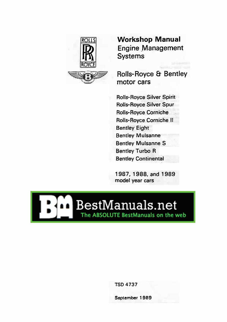
This is the Rolls-Royce & Bentley Engine Management Systems Workshop Manual (TSD-4737) for the 1987, 1988, and 1989 model year cars. It covers the following models:
- Rolls-Royce Silver Spirit
- Rolls-Royce Silver Spur
- Rolls-Royce Corniche
- Rolls-Royce Corniche II
- Bentley Eight
- Bentley Mulsanne
- Bentley Mulsanne S
- Bentley Turbo R
- Bentley Continental
Table of Contents:
- General information
- Fuel injection system
- Fuel system
- Turbocharging system
- Ignition system
- Exhaust emission control system
- Fuel evaporative emission control system
- Crankcase emission control system
- Air intake system
- Throttle linkage
- Special torque tightening figures
- Workshop tools
- Running changes
Printable: Yes
Language: English
Compatibility: Pretty much any electronic device, incl. PC & Mac computers, Android and Apple smartphones & tablet, etc.
Requirements: Adobe Reader (free)


