


WORKSHOP MANUAL 50 cm3
Motor FB-0-1-2-4
GB

Trekker - Squab
CONTENTS
ENGINE PART CYCLE PART
RECOMMENDATIONS
ELECTRIC EQUIPMENT
1
Designation Page
- Contents, ............................................................. 1
- Main characteristics, ............................................ 2
- Maintenance plan, ................................................ 3
- Putting into service, ............................................. 4
- Special tools, ........................................................ 5
- Tightening torques ............................................... 5
Dismantling
Designtation Page
- Removing the engine from the vehicle, ............... 6
- Placing the engine on the support, ...................... 6
- Removing the cooling system, ............................. 6
- Removing the flywheel, ........................................ 6
- Removing the oil pump, ....................................... 7
- Removing the starter motor, ................................. 7
- Removing the carburettor and choke, ................. 7
- Removing the intake valve and connecting part, . 7
- Removing the complete primary drive assy, ........ 7
- Removing the kick starter system, ....................... 8
- Removing the relay unit, ...................................... 8
- Removing the cylinder head, ............................... 8
- Removing the cylinder piston assy, ...................... 9
- Removing the RH housing, .................................. 9
- Removing the crankshaft from the LH housing, .. 9
- Replacing the crankshaft bearings and seals,.. .... 9
- Checking the crankshaft ...................................... 9
Refitting
Designation Page
- Refitting the crankshaft, ..................................... 10
- Closing the engine housings, ............................. 10
- Refitting the piston, ............................................ 10
- Refitting the cylinder, ......................................... 11
- Refitting the cylinder head, ................................ 11
- Refitting the relay unit, ........................................ 11
- Refitting the kick starter system, ........................ 12
- Checking the driven pulley clutch, ..................... 12
- Checking the drive pulley variator, ..................... 12
- Refitting the primary drive, ................................. 12
- Refitting the intake valve and connecting part, .. 13
- Refitting the carburettor, .................................... 13
- Refitting the starter motor, ................................. 13
- Refitting the oil pump and setting, ..................... 14
- Refitting the flywheel, ......................................... 14
- Refitting the cooling system ............................... 14
Designation Page
- Contents, .............................................................. 1
- Main characteristics, ............................................ 2
- Maintenance plan, ................................................ 3
- Putting into service, .............................................. 4
- Tightening torques, ............................................... 5
- Disc brake ........................................................... 14
Designation Page
- Spark plug ............................................................. 2
- Fuel ...................................................................... 4
- Separate lubrication .............................................. 4
- Relay unit ............................................................. 4
Designation Page
- Electronic ignition, ............................................... 15
- Circuits supplied with alternative current, ........... 15
. lighting, ............................................................. 15
. choke, .............................................................. 16
- Resistance check of stator, ................................ 16
- Circuits supplied with direct current, .................. 17
. battery charge, ................................................. 17
. fuel gauge, ........................................................ 18
. oil gauge, ......................................................... 18
. horn, .................................................................. 18
. indicators, .......................................................... 18
. starter motor circuits, ....................................... 19
- Functional diagrams for electric circuits,. 20 and 21
- Key to electric circuits ........................................ 22
Trekker - Squab
TECHNICAL DATAS
Frame
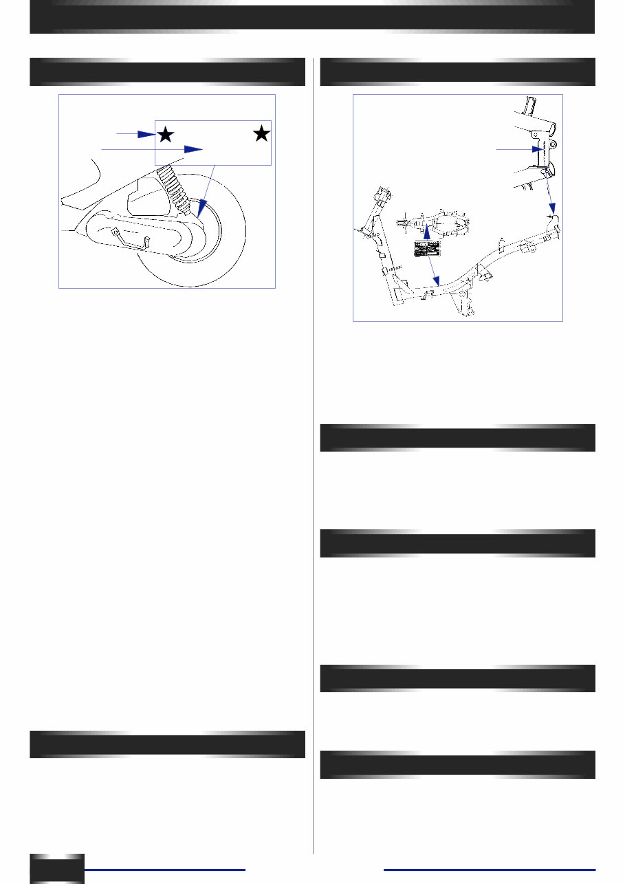
ENGINE MARKING
XXXXXXXX
FB2
Number
Type
Main spécifications
2
IDENTIFICATION MARK
Identification
plate
FB2 ENGINE
Forced-air cooled 2 stroke engine :
- Bore and stroke : ................................................ 40 x 39.1
- Cylinder capacity : ............................................. 49.13cm3
- Compression ratio : ................................................... 6.6:1
- Maximum power (ISO) : .......................................... 3.1 kw
Distribution :
- Exhaust port : ........................................................... 160c°
- Scavenging port : ....................................................... 110°
- Air intake : ..................................... by reed valve induction
- Ignition : ....................... CDI (capacitive-discharge ignition)
- Spark advance : ....................................... 13° before TDC
- Spark plug ................................................... Resistive 5KÙ
..................................................................... NGK - BR7HS
.................................................................. EYQUEM R 850
................................................................. BOSCH WR4AC
- spark plug gap : ..................................................... 0.6mm
Carburettor : .......................................... GURTNER PA350
- Idling speed : .................................... 1800 rpm ± 1 00 rpm
- Initial position of the pilot air adjusting screw :
- Anticlockwise rotation : ..................................... 1/2 to 13/4
- Needle with 3 levels : .................................. clips at the top
- Main jet : ........................................................................ 74
Flywheel magneto :
- Number of poles : ............................................................ 6
- Power : .......................................................... 2500t = 55w
........................................................................ 5000t = 85w
Starter.motor : .................................................... MITSUBA
................................................................ 2000w SM10 129
................................................................. 1500w SM10254
Oil pump : .............................................................. MIKUNI
flow 24cm3 ± 1.7cm3 / hour at 3800 rpm, wide open
throttle. 1CM3 = 0.031 cubic inch
Transmission
- Clutch : .................................... centrifugai, automatic type
- Primary réduction gear : ........................ by a ribbed V-beit
- Life of belt : ...................................................... 1 0 000 km
- Reducer equipped with 2 gearsets.
Identification : VGAS1A . . . . . . . . . . .
- Front tyre : ...................................................... 120/90 x 10
- Rear tyre : ...................................................... 130/90 x 10
Pressure :
- Front : .................................................................... 1,3 bar
- Rear : .................................................................... 1,6 bar
Capacities
- Fuel tank : .............................................................. 6 litres
- Oil tank : .............................................................. 1.3 litres
- Transmission case : ............................................ 0.12 litre
- Under-seat storage compartment : ............................. 3 kg
Dimensions
- Overall length : .................................................... 1760mm
- Overail width : ........................................................ 670mm
Excluding rear view mirror :
Overall height : ...................................................... 1110mm
Excluding rear view mirror :
Wheelbase : .......................................................... 1250mm
Weight
- Complete vehicle dry weight : .................................... 82kg
- Vehicie weight with tanks full : ................................... 88kg
Markings 49cc
- Left hand casing (under the starter motor)
- Cylinder head (front right)
- Cylinder (exhaust flange left hand side)
- Intake pipe (on the front «49»)
Trekker - Squab
MAINTENANCE
PLAN C PLAN A PLAN B
500 km or 3 mois 5000 km or 2500 km* 10000 km or 5000 km*
* reforced maintenance
3
Depending on how the scooter is used, it is recommended to apply either - The normal maintenance plan or
- The reinforced maintenance plan.
The normal maintenance plan includes:
- Visit at 500 km or 3 months Plan A
- Periodic maintenance every 5000 km Plan B
- Periodic maintenance every 10000 km Plan C
The reinforced maintenance plan includes:
- Visit at 500 km Plan A
- Periodic maintenance every 2500 km Plan B
- Periodic maintenance every 5000 km Plan C
The reinforced maintenance is intended for vehicles used in so-called “severe” conditions: door to door sales, intensive urban
use (courrier), short journeys engine cold, areas with dusty atmospheres, frequent use of vehicles at an ambient temperature
above 30°C.
CHECK :
Idle speed adjustment X X X
Throttle X X X
Oil pump control X X X
Functioning of the electric equipment X X X
Front and rear brake control X X X
Fuel pipes X X X
Oil pipes X X X
Front brake fluid pipes X X X
State and pressure of tyres X
State, pressure and wear of tyres X X
Brake fluid level X X X
Level of battery electrolyte X X X
Tightening of nuts and bolts X X X
REPLACE :
Relay unit oil X X
Spark plug X X
Filter element of the intake silencer X X
Front brake pads (if necessary) X
Rear brake linings (if necessary) X X
Drive pulley rollers (if necessary) X X
Transmission belt X
CHECK AND UNCLOG
Piston X
Cylinder head X
Exhaust port X
CHECK AND LUBRICATE
Driven pulley :
movable driven face and needle bearing X
Drive pulley :
movable drive face and rollers X
Kick : driven gear and link ring X
CLEAN AND ADJUST
Carburettor X
VEHICLE TEST
Road test X X X
MAINTENANCE PLAN

Trekker - Squab
INSTRUCTIONS FOR MAKING OPERATIONAL
4
1. Preparation of the battery
(dry charged)
- Remove the battery.
- Remove the six cell caps and the breather tube cap.
- Fill the battery with électrolyte up to the level marked
UPPER LEVEL (35% sulphuric acid 1.28 g/CM3),
Ref : ........................................................... 1 litre : 752740
................................................................ 5 litres : 752741
- Leave the battery to settle for half an hour. Top up the
level if necessary.
- Charge the battery for 1 to 2 hours with a current of
400m.A (0.4A).
- Replace the battery and connect the breather tube.
- Connect up the red positive leads to the battery positive
terminal, then the green negative lead to the battery earth
terminal.
- From then on, the battery can be topped up if necessary,
using distilled water only.
2. Fuel
Capacity : .............................................................. 6 litres
- Conventional 4-star petrol.
- Lead free petrol 98 octanes.
3. Separate lubrication:
Capacity : .......................................................... 1.3 litres.
- Fill up the oil tank with semi-synthetic engine oil for 2-
stroke engines with separate lubrication,
- Type TC (API standard), type TSC3 (ASTM standard), -
- Type FC (JASO standard) or a synthetic oil.
PEUGEOT MOTOCYCLES recommends :
....................................... ESSO : 2T Special performance
......................................................... ESSO : 2T Synthetic
4. Putting fuel and oil circuits into
opération:
- Put one litre of fuel mixture with 4% oil into the fuel tank.
- Fill up the oil tank.
- Start the engine: make sure that the oil circuit is
completely primed. Remove the oil bleed screw from the
pump to allow air in the circuit to escape. When a
continuons stream of oil issues from this hole, replace the
bleed screw with its fiber washer.
For this : disconnect the oil intake hose to the carburettor
and check that it drips, frequency depending on the
engine’s speed.
- Top up the fuel tank with pure 4 star petrol.
5. Checking the oil level in the
transmission case:
- Unscrew and remove the oil filler hole screw A and
make sure that the oil level is flush with the level of the
filling hole. The vehicle must be positioned on its stand
and on a level surface.
Esso Oil SAE 80 W 90
REF : .................................................................... 753009
capacity 0. 1 2 litre
A = 1.2m.daN.
6. Checks before delivery to the
customer:
- In particular, check the tightening of the Wheel nuts ... -
front : .................................................................... 6m daN
- rear : .............................................................. 1Om daN
- Check the tightness of the nuts and bolts.
- Check brake adjustment and eff iciency.
- Cold tyre pressure:
FRONT
- pressure : ......................................................... 1.3 bar
- size : .......................................................... 120/90 x 10
REAR
- pressure : ......................................................... 1.6 bar
- size : .......................................................... 130/90 x 10
- Make sure all lights and signals operate correctly
(taillight, turnsignals, stop light, horn), and various
warning lights.
- vehicle road test.

Trekker - Squab
TIGHTENING TORQUES AND SPECIAL TOOLS
TIGHTENING TORQUES SPECIAL TOOLS
5
Engine
Assembly screws for :
- Housings : ........................................................ 1m.daN
- Covers : ............................................................ 1m.daN
- Intake connecting part : .................................... 1m.daN
- Starter motor : .................................................. 1m.daN
- Stator : .............................................................. 1m.daN
- Sensor : ............................................................ 1m.daN
- Fan : ................................................................. 1m.daN
- Carburettor : .................................................. 0.8m.daN
- Oil pump : ...................................................... 0.8m.daN
- Cylinder head : .............................................. 1.2m.daN
- Drive pulley : ..................................................... 4m.daN
- Driven pulley : ................................................ 4.5m.daN
- Rotor : .............................................................. 4m.daN
- Oil plug : ........................................................ 1.2m.daN
- Spark plug : ...................................................... 2m.daN
Frame
- Front wheel axis nut : ........................................ 6m.daN
- Rear wheel nut : ............................................. 10m.da N
- Engine joint on rod : ........................................... 6m.daN
- Rod joint on chassis : ..................................... 2.2m.daN
- Rear shock absorber upper fixation : .............. 1.6m.daN
- Rear shock absorber lower fixation : .............. 1.6m.daN
- Exhaust nuts on cylinder : .............................. 1.6m.daN
- Handlebar nut : .................................................. 4m.daN
- Steering lock nut : .............................................. 7m.daN
Standard
- Screw and nut ø 5mm : ...................... 0.45 to 0.6m.daN
- Screw and nut ø 6mm : ........................ 0.8 to 1.2m.daN
- Screw and nut ø 8mm : ........................ 1.8 to 2.5m.daN
- Screw and nut ø 1Omm : ........................... 3 to 4m.daN
- Screw and nut ø 12mm : ............................ 5 to 6m.daN
- Service cradle mount ............................................... 64765
- Adjustable adapter for engine service cradle ......... 752026
- Flywheel holder ....................................................... 68570
- Snap ring pliers ..................................................... 752000
- Protective end, small model for flywheel magneto remover
.................................................................................. 68007
- Puiler tool ................................................................ 64706
- Crankshaft end protector ......................................... 69098
- Shouldered centring tool .......................................... 64710
- Screw on torque handle ........................................... 69104
- Compresser tool, ail types of clutch ....................... 752127
- Tubular socket wrench 39 ..................................... 752361
- Adjustable pin type face wrench ............................ 752237
- Set of half sheils 0 52 .............................................. 64709
- Puiler tool .............................................................. 750807
- Support washer ..................................................... 750808
- Surface plate 250 x 160 x 50 ................................. 750541
- Comparator (adapts to pattern plate accessory ..... 750969
- Torque wrench + extension + reducer ..................... 69802
- Flywheel puller supplied with 68007 protector ....... 750806
- Blooking tool .......................................................... 752370
- Pliers for circlips ...................................................... 69117
- Spindle .................................................................. 750069
- Steering tools ........................................................ 752948
Trekker - Squab
REMOVAL
6
64765
752026
68 007
750806
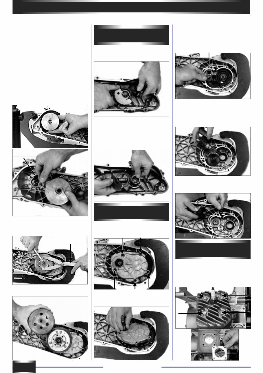
Removal of the engine
- Remove :
- All side casings
- Disconnect :
- Fuel line from the carburettor,
- Fuel tap vacuum hose,
- Oil pump control cable
- Throttle control cable,
- Oil iniet piping at the pump (large
hose)
- Radio interference suppressor cap
- Rear brake control cable
Disconnect :
- The wiring harness on the frame’s
right tube: located at the outlet of the
Flywheel magneto (under the foot
board), choke, starter motor.
Remove :
- The lower anchor bolt of the shock
absorber and the front anchor pin of
the engine.
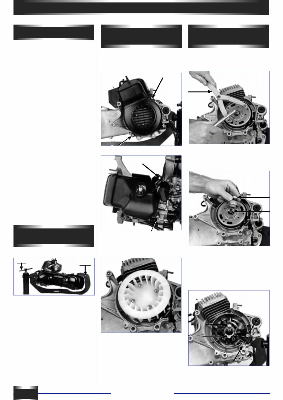
Removal of the flywheel
magneto
- Block the rotor using a notch type pin
752237.
- Remove the nut (right-hand thread).
- Fit the crankshaft end protector
68007 onto the end of the crankshaft.
- Screw the flywheel puller tool 750806
onto the rotor and tighten the centre
bolt until the rotor comes away.
- Remove the 2 fastening screws of
the sensor, as well as the 2 fastening
screws of the stator plate.
- Remove the coil assembly and the
sensor.
Removal of cooling
systern
- Remove the two parts of the fan
covers (4 screws).
- Remove the 4 fastening screws of
the fan and remove the fan.
Fitting of engine on service
cradle
- Place the engine onto the adapter
752026
- Place the assembly on the cradle
mount 64765 clamped in a vice
Trekker - Squab
752370
7
REMOVAL
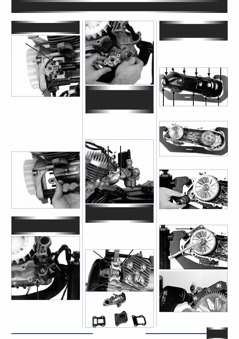
Removal of the oil pump
- Unclip the oil inlet pipe to the
carburettor.
- Unscrew the 2 hex head socket
screws.
- Remove the oil pump and the control
flange.
- Remove the 2 square fastening nuts
Q from their housings.
- Remove the flexible washer lodged
between the pump and the shaft
bearing of the oil pump.
- Adjustment: see page N° 14
Rernoval of the starter
motor
- Free the wire harness from the
support bracket.
- Remove the 2 fastening screws and
washers from the starter motor and
pull out together with «0» ring seal.
Removal of the
carburettor / choke
assembly
- Take off the 2 fastening screws from
the carburettor and remover the
carburettor / choke
assembly, as well as the isothermal
spacer.
Removal of the reed
valve and intake pipe
- Unscrew and remove the 4 fastening
screws.
- Remove the intake pipe, the gasket,
the reed valve assembly and the
second gasket.
Removal of the primary
drive system
You do not have to remove of the kick
starter arm when removing the
crankcase cover.
- Loosen and remove the 11 fastening
screws of the cover.
- Remove the cover with both locating
dowls.
- Remove the starter drive assembly
from the starter motor.
- Hold the starter ring gear with the
tool 752370.
Trekker - Squab
REMOVAL
8
752237
Rdl 12,35x19,75x1
Make careful note of where this tool
comes level with the starter ring gear
plate of the starter motor in order to
make sure, when refitting, that the
pressure plate fits correcte into the
grooves of the crankshaft.
- Loosen the fastening nut (right-hand
thread) of the gear plate of the drive
pulley.
- Remove the nut, washer and plate.
- Remove the belt.
- Remove the drive pulley assembly
(variable speed drive) and the washer
on the engine housing side (12,35 X
19,75 X 1).
- Block the clutch drum with the fly-
wheel pinch bolt no.68570 or the ad-
justable pin type face wrench 752237.
- Loosen the screw, remove the drum
and the clutch driven pulley assembly.
Removal of the kick
starter system
- Actuate the kick starter spindle with
your thumb and remove the drive
ratchet and its washer.
- Remove the kickstarter lever. Using
snipe-nosed pliers (ref. 69117), take
off the circlips, the washer, then
remove the kick starter toothed
section, the pull-back spring and the
bushing.
Removing the cylinder
head
- Unscrew in a crosswise order the 4
screws securing the cylinder head and
cylinder block assembly.
- Remove the cylinder head and
gasket.
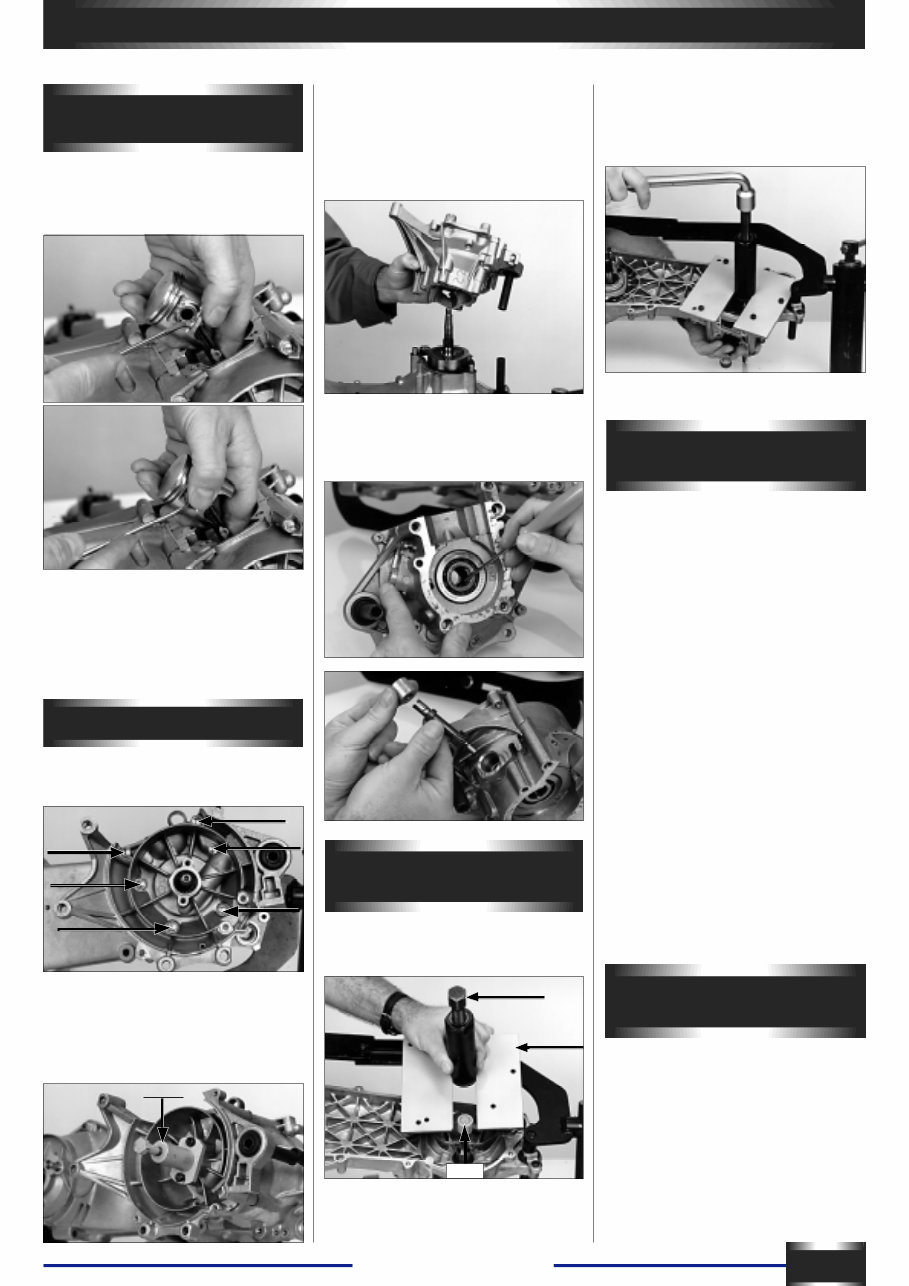
Dismantling the
transmission case
After draining the transmission case:
- Remove the 5 screws securing the
cover.
- Remove the cover with the drive
shaft (or input shaft), the gasket and
both locating dowls.
- Removal of the drive shaft (or input
shaft) from the transmission cover is
done using a mallet.
- Remove the thrust washer from the
counter shaft (14.3x26xO.5).
- Drain the transmission case
completely before removing the final
shaft (or output shaft) in order to avoid
contamining brake linings.
- Pull out the final shaft (output shaft).
- Pull out the countershaft as well as
its friction washers (1 4.3 x 26 x 0.5)
and flexible washer (1 4 x 22 x 1.5).
Trekker - Squab
REMOVAL
9
750807
64706
752168
69098
Removing the cylinder
and piston
- Remove the cylinder and cylinder-to-
crankcase gasket.
- Pack the crankcase mouth with
clean cloth or paper.
- Lean the engine to the left and take
out the wrist pin’s RH snap ring.
- Push the wrist pin from the left to the
right; this opération does not require
use of a strap.
- Take out the needie bearing race.
Opening the crankcase
- Remove the 6 screws securing the
RH crankcase half.
- Fit the crankshaft end protector
68007 onto the end of the crankshaft.
- Position the puller tool 750807 onto
the crankcase half.
- Turn the inner thrust bolt of tool
750807 until the crankcase halves
split Hold the connecting rod so that it
does not knock against the crankcase
halves.
- Remove the RH half casing.
- Remove the gasket and both
locating dowls. Remove the drive
shaft of the oil pump and its locating
bush.
Changing the bearings
and seals
- Heat the crankcase halves evenly to
90° so that they expand. The bearings
will drop out, drive out the seals.
- Fit the new bearings while the
crankcase halves are still warm.
- Fit the oil seals in place.
- The oil seal on the drive pulley side
should fit flush with the crankcase, the
lips being on the fl.ywheel housing
side. The seal on the flywheel side
should be approximately 9mm in.
Note:
If the crankshaft bearings remain on
the crankshaft; use the puller tool
64706 with the half shells 64709 (diam
= 52) to remove them. Do not forget
to fit the crankshaft end protector
69098 onto the ends of the crankshaft.
Removing the crankshaft
assembly
- Fit the crankshaft end protector
69098 onto the end of the crankshaft.
-Fit puller tool 647706 with the plate
752168 onto the crankcase.
- Secure the plate to the crankcage by
tightening the 4 screws.
- Withdraw the crankshaft by turning
the inner thrust bolt of tool 64706.
Checking the crankshaft
assembly
- The maximum side play of the
conrod big end should not exceed:
0.5mm.
- Check crankshaft alignement as
shown in the drawing (surface plate
750541, comparator 750969
The values measured at the ends
should not exceed 0.12mm.
You're Reading a Preview
What's Included?
Fast Download Speeds
Online & Offline Access
Access PDF Contents & Bookmarks
Full Search Facility
Print one or all pages of your manual
$39.99
Peugeot 50cc Horizontal Cylinder Iae Engine Full Service & Repair Manual
Viewed 28 Times Today

What's Included?
Fast Download Speeds
Online & Offline Access
Access PDF Contents & Bookmarks
Full Search Facility
Print one or all pages of your manual
$39.99

Secure transaction
What's Included?
Fast Download Speeds
Online & Offline Access
Access PDF Contents & Bookmarks
Full Search Facility
Print one or all pages of your manual
Description
- This is a complete factory service repair workshop manual for the Peugeot 50cc Horizontal Cylinder Iae Engine.
- It is available for instant access on your computer, tablet, or smartphone.
- Designed for professional mechanics and DIY enthusiasts, this professional manual covers all repairs, servicing, and troubleshooting procedures.
- The manual is highly detailed, containing hundreds of pages with detailed photos, diagrams, step-by-step instructions, and highly detailed exploded diagrams and pictures.
- Users have the option to print out a single page or the entire manual.
- It can be used on multiple computers without any limitations or trial periods.
- There is no expiry date, renewal fee, or limitations on usage.
- Compatible with all Windows and MAC computers.
Thanks for considering this comprehensive manual for your repair needs.


