Perkins 404D-22TA Diesel Engine Factory Service & Work Shop Manual
What's Included?
Lifetime Access
Fast Download Speeds
Online & Offline Access
Access PDF Contents & Bookmarks
Full Search Facility
Print one or all pages of your manual
KENR6226-01 April 2008 Disassembly and Assembly 402D-403D-404D Industrial Engine GG (Engine) GH (Engine) GJ (Engine) GK (Engine) GL (Engine) GM (Engine) GN (Engine) GP (Engine) GQ (Engine) GS (Engine) SAFETY.CAT.COM
Important Safety Information Most accidents that involve product operation, maintenance and repair are caused by failure to observe basic safety rules or precautions. An accident can often be avoided by recognizing potentially hazardous situations before an accident occurs. A person must be alert to potential hazards. This person should also have the necessary training, skills and tools to perform these functions properly. Improper operation, lubrication, maintenance or repair of this product can be dangerous and could result in injury or death. Do not operate or perform any lubrication, maintenance or repair on this product, until you have read and understood the operation, lubrication, maintenance and repair information. Safety precautions and warnings are provided in this manual and on the product. If these hazard warnings are not heeded, bodily injury or death could occur to you or to other persons. The hazards are identified by the “Safety Alert Symbol” and followed by a “Signal Word” such as “DANGER”, “WARNING” or “CAUTION”. The Safety Alert “WARNING” label is shown below. The meaning of this safety alert symbol is as follows: Attention! Become Alert! Your Safety is Involved. The message that appears under the warning explains the hazard and can be either written or pictorially presented. Operations that may cause product damage are identified by “NOTICE” labels on the product and in this publication. Perkins cannot anticipate every possible circumstance that might involve a potential hazard. The warnings in this publication and on the product are, therefore, not all inclusive. If a tool, procedure, work method or operating technique that is not specifically recommended by Perkins is used, you must satisfy yourself that it is safe for you and for others.You should also ensure that the product will not be damaged or be made unsafe by the operation, lubrication, maintenance or repair procedures that you choose. The information, specifications, and illustrations in this publication are on the basis of information that was available at the time that the publication was written. The specifications, torques, pressures, measurements, adjustments, illustrations, and other items can change at any time. These changes can affect the service that is given to the product. Obtain the complete and most current information before you start any job. Perkins dealers or Perkins distributors have the most current information available. When replacement parts are required for this product Perkins recommends using Perkins replacement parts. Failure to heed this warning can lead to prema- ture failures, product damage, personal injury or death.
KENR6226-01 3 Table of Contents Table of Contents Disassembly and Assembly Section Fuel Filter Base - Remove and Install (403D-11, 403D-15, 403D-15T, 403D-17, 404D-15, 404D-22, 404D-22T and 404D-22TA Engines) ..................... 4 Fuel Filter Base - Remove and Install (402D-05 and 403D-07 Engines) ................................................. 5 Fuel Transfer Pump - Remove and Install (Mechanical Fuel Transfer Pump) ............................................. 7 Fuel Transfer Pump - Remove and Install (Electrical Fuel Transfer Pump) ............................................. 8 Fuel Injection Lines - Remove and Install .............. 9 Fuel Shutoff Solenoid - Remove and Install ........ 12 Fuel Injection Pump - Remove and Install ........... 13 Fuel Injector - Remove and Install ....................... 15 Turbocharger - Remove and Install ..................... 16 Exhaust Manifold - Remove and Install ............... 18 Inlet and Exhaust Valve Springs - Remove and Install ................................................................... 19 Inlet and Exhaust Valves - Remove and Install .... 22 Engine Oil Line - Remove and Install ................... 24 Engine Oil Cooler - Remove and Install ............... 26 Engine Oil Relief Valve - Remove and Install ....... 27 Engine Oil Pump - Remove .................................. 28 Engine Oil Pump - Install ...................................... 30 Water Pump - Remove and Install (403D-11, 403D-15, 403D-15T, 403D-17, 404D-15, 404D-22, 404D-22T and 404D-22TA Engines) ................... 32 Water Pump - Remove and Install (402D-05 and 403D-07 Engines) ............................................... 33 Water Temperature Regulator Housing - Remove and Install .................................................................. 35 Water Temperature Regulator - Remove and Install (402D-05 and 404D-07 Engines) ........................ 36 Water Temperature Regulator - Remove and Install (403D-11, 403D-15, 403D-15T, 403D-17, 404D-15, 404D-22, 404D-22T and 404D-22TA Engines) ... 38 Flywheel - Remove ............................................... 39 Flywheel - Install ................................................... 40 Crankshaft Rear Seal - Remove and Install ......... 41 Crankshaft Wear Sleeve (Rear) - Remove and Install ................................................................... 43 Flywheel Housing - Remove and Install .............. 44 Flywheel Housing - Remove and Install (Engines with Flywheel Housing and Back Plate) ..................... 45 Crankshaft Pulley - Remove and Install ............... 47 Crankshaft Front Seal - Remove and Install ......... 48 Housing (Front) - Remove .................................... 49 Housing (Front) - Disassemble ............................. 50 Housing (Front) - Assemble .................................. 52 Housing (Front) - Install ........................................ 55 Crankcase Breather - Remove and Install (Turbocharged Engines) ..................................... 56 Crankcase Breather - Remove and Install (Naturally Aspirated Engines) .............................................. 58 Valve Mechanism Cover - Remove and Install ..... 60 Rocker Shaft and Pushrod - Remove ................... 62 Rocker Shaft - Disassemble (403D-15, 403D-15T, 403D-17, 404D-22, 404D-22T and 404D-22TA Engines) .............................................................. 62 Rocker Shaft - Disassemble (402D-05, 403D-07, 403D-11 and 404D-15 Engines) ......................... 63 Rocker Shaft - Assemble (403D-15, 403D-15T,403D-17, 404D-22, 404D-22T and 404D-22TA Engines) ........................................... 64 Rocker Shaft - Assemble (402D-05, 403D-07, 403D-11 and 404D-15 Engines) ......................... 65 Rocker Shaft and Pushrod - Install ....................... 66 Cylinder Head - Remove ...................................... 67 Cylinder Head - Install .......................................... 69 Lifter Group - Remove and Install ......................... 71 Camshaft - Remove .............................................. 72 Camshaft - Disassemble ....................................... 73 Camshaft - Assemble ........................................... 74 Camshaft - Install .................................................. 74 Engine Oil Pan - Remove and Install ................... 76 Pistons and Connecting Rods - Remove .............. 77 Pistons and Connecting Rods - Disassemble ....... 78 Pistons and Connecting Rods - Assemble ........... 80 Pistons and Connecting Rods - Install .................. 81 Connecting Rod Bearings - Remove (Connecting rods in position) ................................................... 83 Connecting Rod Bearings - Install (Connecting rods in position) ........................................................... 83 Connecting Rod Bearings - Install ........................ 84 Crankshaft Main Bearings - Remove .................... 85 Crankshaft Main Bearings - Install ........................ 86 Crankshaft - Remove ............................................ 88 Crankshaft - Install ................................................ 89 Bearing Clearance - Check ................................... 90 Coolant Temperature Switch - Remove and Install (403D-11, 403D-15, 403D-15T, 403D-17, 404D-15, 404D-22, 404D-22T and 404D-22TA Engines) ... 91 Coolant Temperature Switch - Remove and Install (402D-05 and 403D-07 Engines) ........................ 92 Engine Oil Pressure Switch - Remove and Install ............................................................................. 93 Glow Plugs - Remove and Install ......................... 95 V-Belts - Remove and Install ................................ 96 Fan - Remove and Install ..................................... 96 Alternator - Remove and Install (65 Amp and 85 Amp Alternators) ......................................................... 97 Alternator - Remove and Install (55 Amp Alternator) ........................................................... 99 Alternator - Remove and Install (40 Amp Alternator) ........................................................... 99 Alternator - Remove and Install (14 Amp and 15 Amp Alternators) ....................................................... 101 Electric Starting Motor - Remove and Install ..... 102 Index Section Index ................................................................... 103
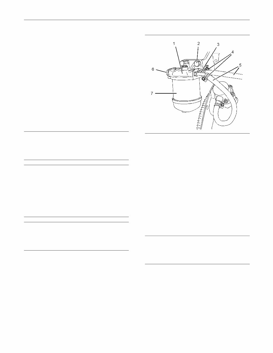
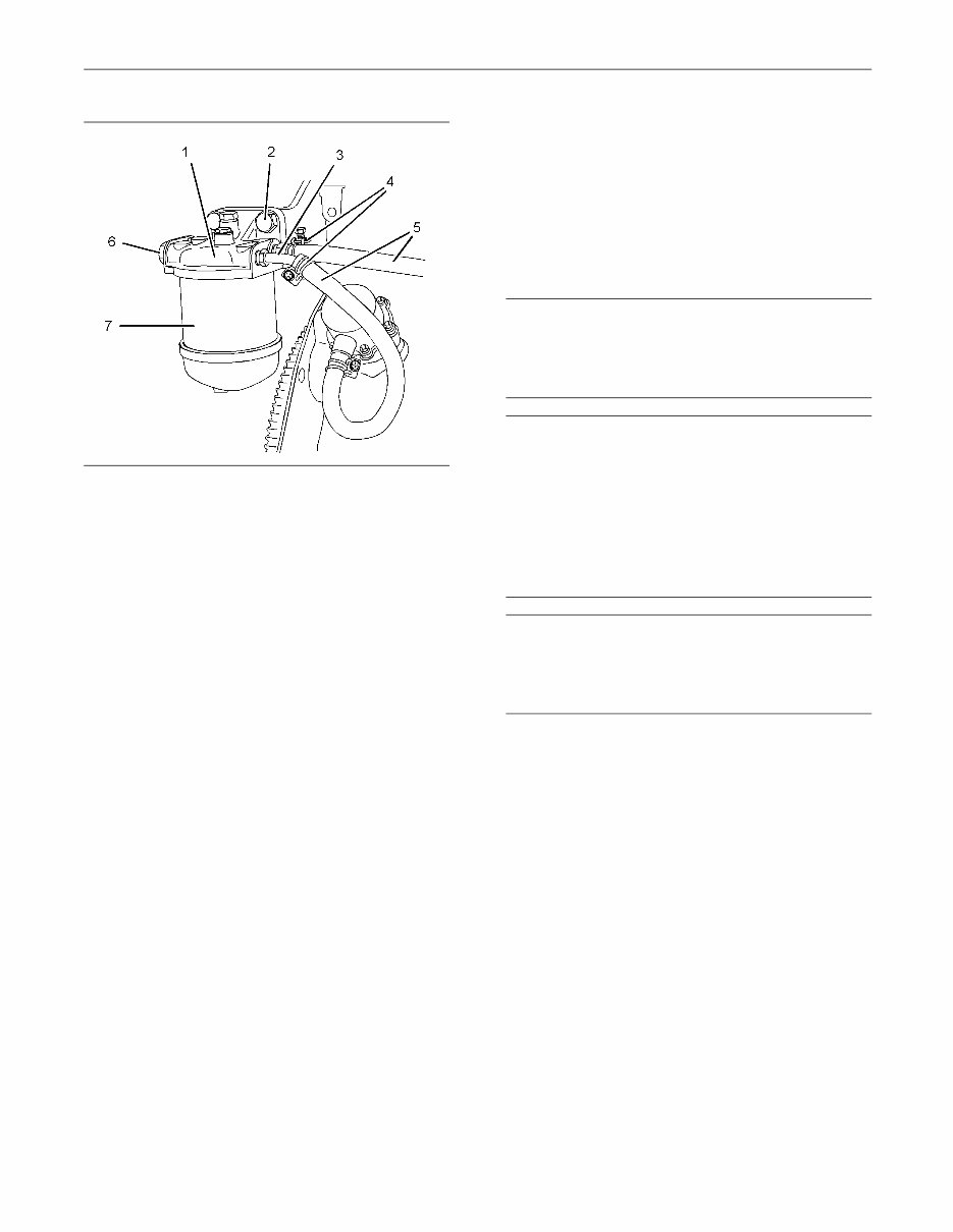
4 KENR6226-01 Disassembly and Assembly Section Disassembly and Assembly Section i02959949 Fuel Filter Base - Remove and Install (403D-11, 403D-15, 403D-15T, 403D-17, 404D-15, 404D-22, 404D-22T and 404D-22TA Engines) Removal Procedure NOTICE Do not allow dirt to enter the fuel system. Thoroughly clean the area around a fuel system component that will be disconnected. Fit a suitable cover over discon- nected fuel system component. NOTICE Care must be taken to ensure that fluids are contained during performance of inspection, maintenance, test- ing, adjusting and repair of the product. Be prepared to collect the fluid with suitable containers before open- ing any compartment or disassembling any compo- nent containing fluids. Dispose of all fluids according to local regulations and mandates. NOTICE Keep all parts clean from contaminants. Contaminants may cause rapid wear and shortened component life. Note: Place identification marks on all hoses for installation purposes. Plug all hoses and all the ports in the fuel filter base. This helps prevent fluid loss, and this helps to keep contaminants from entering the system. 1. Turn the fuel supply to the OFF position. g01302737 Illustration 1 Typical example 2. Loosen hose clamps (4) and disconnect hoses (5). 3. If necessary, remove fuel filter element (7) from fuel filter base (1). Refer to Operation and Maintenance Manual, “Fuel System Filter - Replace”. 4. Remove fasteners (2) and remove fuel filter base (1) from the mounting bracket. 5. If necessary, remove plugs (6) and washers (not shown) from fuel filter base (1). Remove tube assemblies (3) and rubber olives (not shown) from fuel filter base (1). Installation Procedure NOTICE Keep all parts clean from contaminants. Contaminants may cause rapid wear and shortened component life. Note: If the engine is equipped with a hand priming pump, the hand priming pump is mounted on the fuel filter base. The assembly of the fuel filter base and the hand priming pump is not serviceable. 1. Ensure that the fuel filter base is clean and free from damage. If necessary, replace the fuel filter base.
KENR6226-01 5 Disassembly and Assembly Section g01302737 Illustration 2 Typical example 2. If necessary, install new rubber olives (not shown) onto tube assemblies (3). Install tube assemblies (3) to fuel filter base (1). Ensure the correct orientation of the tube assemblies. Tighten the nuts to a torque of 9 N·m (80 lb in). 3. Install washers (not shown) onto plugs (6). Install plugs (6) to fuel filter base (1). Tighten the plugs to a torque of 23 N·m (17 lb ft). 4. Align fuel filter base (1) with the mounting bracket. Install fasteners (2). Tighten the fasteners to a torque of 50 N·m (37 lb ft). 5. If necessary, install a new fuel filter element (7) to fuel filter base (1). Refer to Operation and Maintenance Manual, “Fuel System Filter - Replace”. 6. Connect hoses (5) and tighten hose clamps (4). Note: Ensure that the hoses do not contact any other engine components. 7. Turn the fuel supply to the ON position. 8. Remove the air from the fuel system. Refer to Operation and Maintenance Manual, “Fuel System - Prime”. i02645711 Fuel Filter Base - Remove and Install (402D-05 and 403D-07 Engines) Removal Procedure NOTICE Do not allow dirt to enter the fuel system. Thoroughly clean the area around a fuel system component that will be disconnected. Fit a suitable cover over discon- nected fuel system component. NOTICE Care must be taken to ensure that fluids are contained during performance of inspection, maintenance, test- ing, adjusting and repair of the product. Be prepared to collect the fluid with suitable containers before open- ing any compartment or disassembling any compo- nent containing fluids. Dispose of all fluids according to local regulations and mandates. NOTICE Keep all parts clean from contaminants. Contaminants may cause rapid wear and shortened component life. Note: Place identification marks on all hoses for installation purposes. Plug all hoses and all the ports in the fuel filter base. This helps prevent fluid loss, and this helps to keep contaminants from entering the system. 1. Turn the fuel supply to the OFF position.
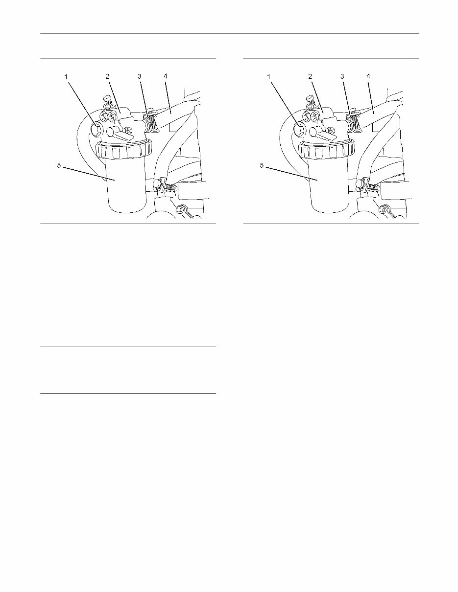
6 KENR6226-01 Disassembly and Assembly Section g01303701 Illustration 3 Typical example 2. Loosen hose clamps (3) and disconnect hoses (4). 3. If necessary, remove fuel filter element (5). Refer to Operations and Maintenance Manual, “Fuel System Filter - Replace”. 4. Remove bolt (1) and remove fuel filter base (2) from the mounting bracket. Installation Procedure NOTICE Keep all parts clean from contaminants. Contaminants may cause rapid wear and shortened component life. 1. Ensure that the fuel filter base is clean and free from damage. If necessary, replace the fuel filter base. g01303701 Illustration 4 Typical example 2. Align fuel filter base (2) with the mounting bracket. Install bolt (1). Tighten the bolt to a torque of 25 N·m (18 lb ft). 3. If necessary, install a new fuel filter element (6) to fuel filter base (2). Refer to Operation and Maintenance Manual, “Fuel System Filter - Replace”. 4. Connect hoses (4) and tighten hose clamps (3). Note: Ensure that the hoses do not contact any other engine components. 5. Turn the fuel supply to the ON position. 6. Remove the air from the fuel system. Refer to Operation and Maintenance Manual, “Fuel System - Prime”.
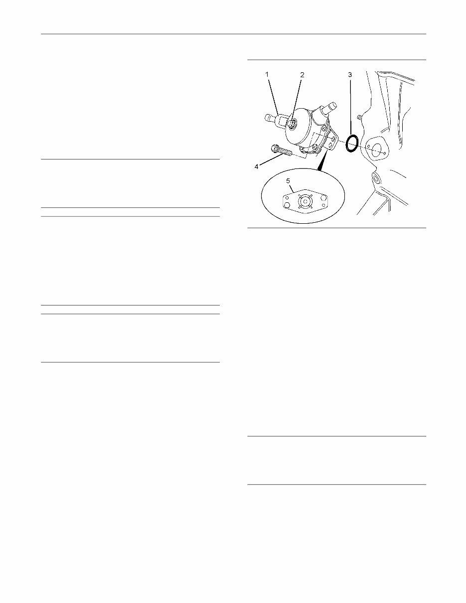
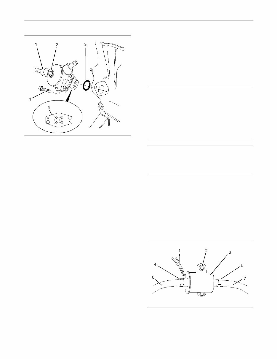
KENR6226-01 7 Disassembly and Assembly Section i02645722 Fuel Transfer Pump - Remove and Install (Mechanical Fuel Transfer Pump) Removal Procedure NOTICE Do not allow dirt to enter the fuel system. Thoroughly clean the area around a fuel system component that will be disconnected. Fit a suitable cover over discon- nected fuel system component. NOTICE Care must be taken to ensure that fluids are contained during performance of inspection, maintenance, test- ing, adjusting and repair of the product. Be prepared to collect the fluid with suitable containers before open- ing any compartment or disassembling any compo- nent containing fluids. Dispose of all fluids according to local regulations and mandates. NOTICE Keep all parts clean from contaminants. Contaminants may cause rapid wear and shortened component life. Note: Place identification marks on all hoses for installation purposes. Plug all hoses and all the ports in the fuel transfer pump. This helps prevent fluid loss, and this helps to keep contaminants from entering the system. 1. Turn the fuel supply to the OFF position. g01326306 Illustration 5 Typical example Note: The fuel transfer pump can be oriented in two positions. Before removing the fuel transfer pump from the cylinder block, note the orientation of flange (5) on fuel transfer pump (1) for assembly. 2. Loosen the hose clamps and disconnect the hoses (not shown) from fuel transfer pump (1). 3. Evenly loosen bolts (4) and remove fuel transfer pump (1) from the cylinder block. Note: In order to remove the fuel transfer pump, it may be necessary to rotate the crankshaft until the operating plunger of the fuel transfer pump is not under pressure. 4. Remove O-ring seal (3) from fuel transfer pump (1). Installation Procedure NOTICE Keep all parts clean from contaminants. Contaminants may cause rapid wear and shortened component life.
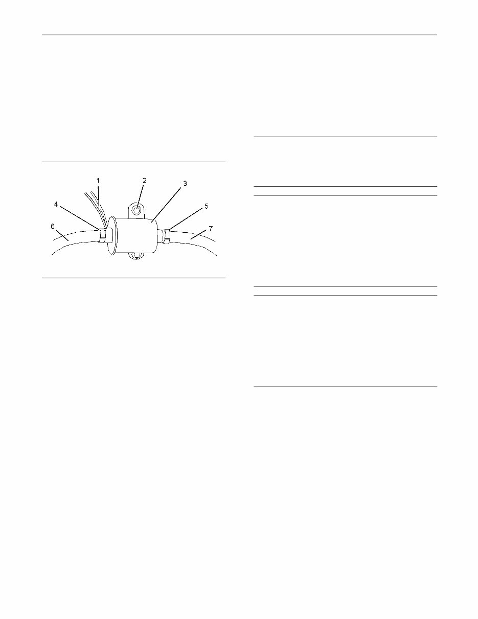
8 KENR6226-01 Disassembly and Assembly Section g01326306 Illustration 6 Typical example 1. Clean the mating surfaces of the cylinder block and flange (5) on the fuel transfer pump. Note: Ensure that the camshaft lobe for the fuel transfer pump is at minimum lift before the fuel transfer pump is installed. The fuel transfer pump can be oriented in two positions. Ensure that the fuel transfer pump is oriented in the correct position. 2. Install a new O-ring seal (3) to fuel transfer pump (1). 3. Lubricate the operating plunger of fuel transfer pump (1) with clean engine oil. 4. Position fuel transfer pump (1) on the cylinder block. Ensure that the operating plunger is positioned correctly on the camshaft lobe. Install bolts (4). Tighten the bolts to a torque of 6 N·m (53 lb in). 5. Connect the hoses (not shown) to fuel transfer pump (1). Tighten the hose clamps. Note: The inlet for the fuel transfer pump can be rotated 360 degrees by loosening bolt (2). The fuel inlet is adjustable in 15 degree increments. If adjustment is made to the position of the fuel inlet, tighten bolt (2) to a torque of 2.5 N·m (22 lb in). 6. Turn the fuel supply to the ON position. 7. Prime the fuel system. Refer to Systems Operation, Testing and Adjusting, “Fuel System - Prime” for additional information. i02645719 Fuel Transfer Pump - Remove and Install (Electrical Fuel Transfer Pump) Removal Procedure NOTICE Care must be taken to ensure that fluids are contained during performance of inspection, maintenance, test- ing, adjusting and repair of the product. Be prepared to collect the fluid with suitable containers before open- ing any compartment or disassembling any compo- nent containing fluids. Dispose of all fluids according to local regulations and mandates. NOTICE Keep all parts clean from contaminants. Contaminants may cause rapid wear and shortened component life. Note: Put identification marks on all hoses, on all hose assemblies, on wires and on all tube assemblies for installation purposes. Plug all hose assemblies and tube assemblies. This helps to prevent fluid loss and this helps to keep contaminants from entering the system. 1. Turn the fuel supply to the OFF position. 2. Turn the battery disconnect switch to the OFF position. g01304057 Illustration 7 Typical example 3. Disconnect harness assembly (1).
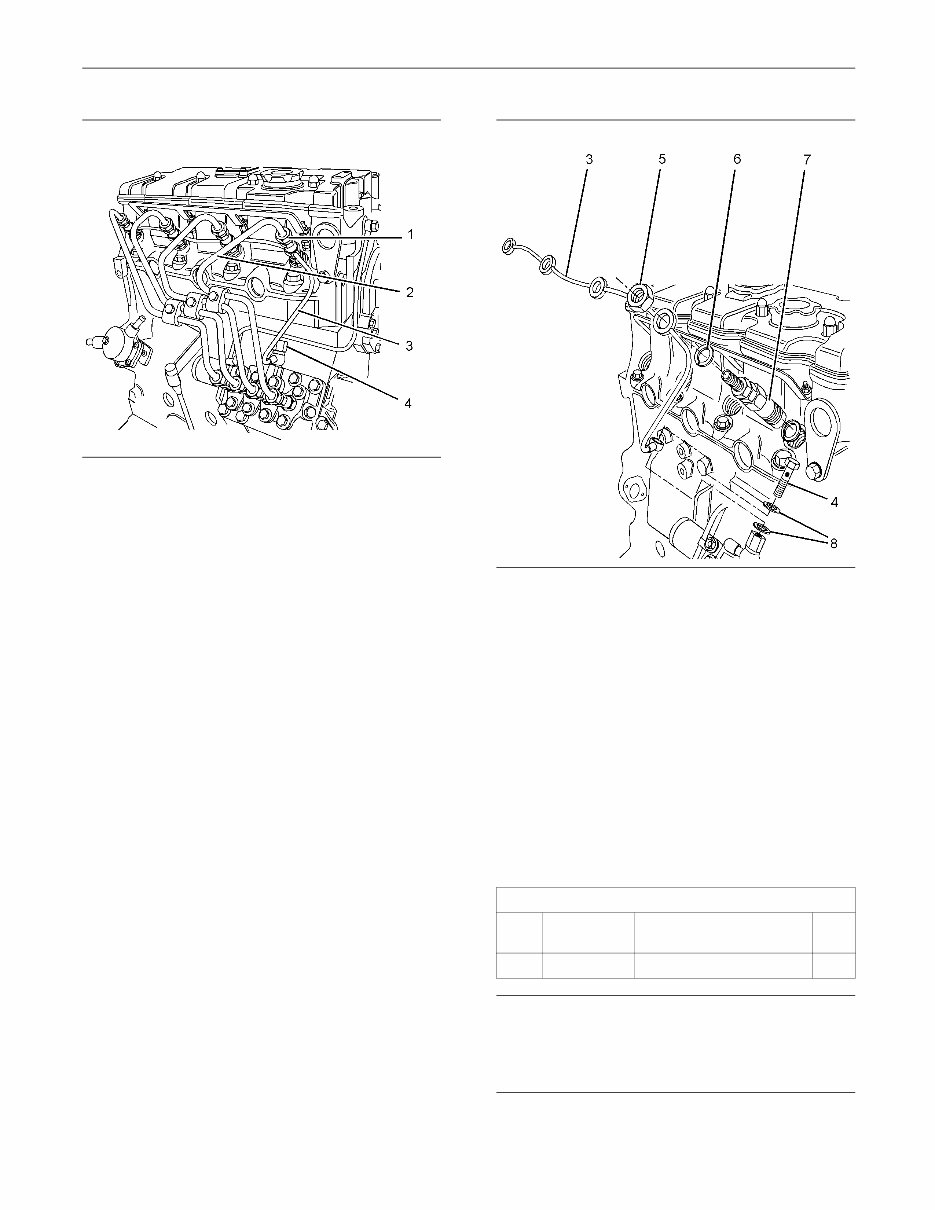
KENR6226-01 9 Disassembly and Assembly Section 4. Loosen hose clamps (4) and (5). Disconnect hoses (6) and (7). 5. Remove bolts (2) and remove electric transfer pump (3). Installation Procedure 1. Ensure that the electric transfer pump is clean and free from damage. If necessary, replace the electric transfer pump. g01304057 Illustration 8 Typical example 2. Position electric transfer pump (3) on the mounting and install bolts (2). 3. Tighten bolts (2) to a torque of 9 N·m (79 lb in). 4. Connect hoses (6) and (7). Tighten hose clamps (4) and (5). 5. Connect harness assembly (1). 6. Turn the fuel supply to the ON position. 7. Turn the battery disconnect switch to the ON position. 8. Remove the air from the fuel system. Refer to Operation and Maintenance Manual, “Fuel System - Prime”. i02959953 Fuel Injection Lines - Remove and Install Removal Procedure NOTICE Keep all parts clean from contaminants. Contaminants may cause rapid wear and shortened component life. NOTICE Care must be taken to ensure that fluids are contained during performance of inspection, maintenance, test- ing, adjusting and repair of the product. Be prepared to collect the fluid with suitable containers before open- ing any compartment or disassembling any compo- nent containing fluids. Dispose of all fluids according to local regulations and mandates. NOTICE Do not let the tops of fuel injectors turn when the fuel line nuts are loosened or tightened. The fuel injectors will be damaged if the top of the injector turns in the body. The engine will be damaged if a defective fuel injector is used because the shape of fuel (spray pattern) that comes out of the nozzle will not be correct. Note: Place identification marks on all tube assemblies for installation. Plug all lines and tube assemblies in order to prevent contamination. 1. Turn the fuel supply to the OFF position.
10 KENR6226-01 Disassembly and Assembly Section g01326550 Illustration 9 Typical example 2. Disconnect nuts (1) for fuel injection lines (2) from the fuel injectors. 3. Disconnect nuts (1) for fuel injection lines (2) from the fuel injection pump. 4. Remove fuel injection lines (2) from the engine as a unit. 5. Use suitable caps in order to plug the open ports of the fuel injection pump immediately. 6. The 403D-15, 403D-15T, 403D-17, 404D-22, 404D-22T and 404D-22TA engines have a rigid fuel return line. For engines with a rigid fuel return line, remove banjo bolt (4) from fuel return line (3). Remove washers (8). The 402D-05, 403D-07, 403D-11 and 404D-15 engines have a flexible fuel return hose. For engines with a flexible fuel return hose, disconnect the hose from the fuel injection pump. g01326555 Illustration 10 Typical example 7. Remove nuts (5) from fuel injectors (7). Note: For engines with a rigid fuel return line, ensure that the fuel return line is not distorted when the nuts are loosened. 8. Remove fuel return line (3) and washers (6) from fuel injectors (7). 9. Use suitable caps in order to plug the fuel injectors immediately. Installation Procedure Table 1 Required Tools Tool Part Number Part Name Qty A 27610294 Injector Pipe Nut Tool 1 NOTICE Keep all parts clean from contaminants. Contaminants may cause rapid wear and shortened component life.
Upon purchasing this manual, you will receive a .PDF file containing an email contact. After contacting us, you will receive a reply with a link to access the manual for your Perkins 404D-22TA Diesel Engine.
This comprehensive manual covers every aspect of your machine, providing detailed guidance on every nut and bolt. With hundreds of pages, it equips you to address various issues, from routine maintenance like oil changes to more complex tasks such as transmission swaps. The manual includes numerous illustrations to assist you and features easy-to-understand text throughout.
Utilize the search function to navigate the manual efficiently and print the necessary pages as needed. This Factory Service Repair Manual offers a step-by-step approach to maintaining and repairing your machine, imparting the same expertise as that of factory-trained technicians.
By leveraging the knowledge within this service repair manual, any owner can confidently make informed decisions regarding the maintenance and repair of their machine.
Our commitment extends beyond providing a high-quality service manual; we also ensure excellent customer service, guaranteeing your satisfaction.
Recently Viewed
5,521,897Happy Clients
2,594,462eManuals
1,120,453Trusted Sellers
15Years in Business
Price:
Actual Price:
Perkins 404D-22TA Diesel Engine Factory Service & Work Shop Manual