

Perkins 1103 and 1104,2490/1500 manual collection
What's Included?
Fast Download Speeds
Offline Viewing
Access Contents & Bookmarks
Full Search Facility
Print one or all pages of your manual

Perkins 1103 &1104 Series
WORKSHOP MANUAL
Disassembly and Assembly
3 and 4 cylinder, naturally aspirated, and turbocharged
diesel engines for agricultural and industrial use
Publication SENR9779-00
© Proprietary information of Perkins Engines Company Limited 2004, all rights reserved.
The information is correct at the time of print.
Published by Technical Publications.
Perkins Engines Company Limited, Peterborough, PE1 5NA, England
Important Safety Information
Most accidents that involve product operation, maintenance and repair are caused by failure to
observe basic safety rules or precautions. An accident can often be avoided by recognizing potentially
hazardous situations before an accident occurs. A person must be alert to potential hazards. This
person should also have the necessary training, skills and tools to perform these functions properly.
Improper operation, lubrication, maintenance or repair of this product can be dangerous and
could result in injury or death.
Do not operate or perform any lubrication, maintenance or repair on this product, until you have
read and understood the operation, lubrication, maintenance and repair information.
Safety precautions and warnings are provided in this manual and on the product. If these hazard
warnings are not heeded, bodily injury or death could occur to you or to other persons.
The hazards are identified by the “Safety Alert Symbol” and followed by a “Signal Word” such as
“DANGER”, “WARNING” or “CAUTION”. The Safety Alert “WARNING” label is shown below.
The meaning of this safety alert symbol is as follows:
Attention! Become Alert! Your Safety is Involved.
The message that appears under the warning explains the hazard and can be either written or
pictorially presented.
Operations that may cause product damage are identified by “NOTICE” labels on the product and in
this publication.
Perkins cannot anticipate every possible circumstance that might involve a potential hazard. The
warnings in this publication and on the product are, therefore, not all inclusive. If a tool, procedure,
work method or operating technique that is not specifically recommended by Perkins is used,
you must satisfy yourself that it is safe for you and for others.You should also ensure that the
product will not be damaged or be made unsafe by the operation, lubrication, maintenance or
repair procedures that you choose.
The information, specifications, and illustrations in this publication are on the basis of information that
was available at the time that the publication was written. The specifications, torques, pressures,
measurements, adjustments, illustrations, and other items can change at any time. These changes can
affect the service that is given to the product. Obtain the complete and most current information before
you start any job. Perkins dealers or Perkins distributors have the most current information available.
When replacement parts are required for this
product Perkins recommends using Perkins
replacement parts.
Failure to heed this warning can lead to prema-
ture failures, product damage, personal injury or
death.

3
Table of Contents
Table of Contents
Disassembly and Assembly Section
Fuel Priming Pump - Remove and Install .............. 4
Fuel Filter Base - Remove and Install .................... 5
Fuel Injection Lines - Remove ............................... 6
Fuel Injection Lines - Install ................................... 7
Fuel Injector Cover - Remove and Install ................ 8
Fuel Injection Pump - Remove (Delphi DP210) ...... 8
Fuel Injection Pump - Remove (Bosch EPVE for the
1104 engines only) .............................................. 10
Fuel Injection Pump - Install (Delphi DP210) ........ 11
Fuel Injection Pump - Install (Bosch EPVE for the
1104 engines only) .............................................. 13
Fuel Injector - Remove ......................................... 14
Fuel Injector - Install ............................................ 15
Turbocharger - Remove ........................................ 16
Turbocharger - Install ............................................ 17
Exhaust Manifold - Remove and Install ............... 18
Exhaust Elbow - Remove and Install (Option for Four
Cylinder Engines Only) ....................................... 20
Inlet and Exhaust Valve Springs - Remove and
Install ................................................................... 21
Inlet and Exhaust Valves - Remove and Install ..... 23
Inlet and Exhaust Valve Guides - Remove and
Install ................................................................... 26
Inlet and Exhaust Valve Seat Inserts - Remove and
Install ................................................................... 28
Engine Oil Filter Base - Remove and Install ........ 30
Engine Oil Cooler - Remove ................................. 34
Engine Oil Cooler - Install ..................................... 36
Engine Oil Relief Valve - Remove and Install (Engine
Oil Pump) ............................................................ 37
Engine Oil Relief Valve - Remove and Install
(Balancer Unit for the 1104 engines only) ........... 39
Engine Oil Pump - Remove (Engines Without a
Balancer) ............................................................. 40
Engine Oil Pump - Install (Engines Without a
Balancer) ............................................................. 40
Water Pump - Remove ......................................... 41
Water Pump - Disassemble ................................. 42
Water Pump - Assemble ...................................... 43
Water Pump - Install ............................................. 45
Water Temperature Regulator - Remove and Install
............................................................................. 46
Flywheel - Remove ............................................... 48
Flywheel - Install ................................................... 49
Crankshaft Rear Seal - Remove ........................... 50
Crankshaft Rear Seal - Install ............................... 50
Crankshaft Wear Sleeve (Rear) - Remove ............ 52
Crankshaft Wear Sleeve (Rear) - Install ............... 53
Flywheel Housing - Remove and Install ............... 53
Crankshaft Pulley - Remove and Install ............... 55
Crankshaft Front Seal - Remove ........................... 55
Crankshaft Front Seal - Install .............................. 56
Crankshaft Wear Sleeve (Front) - Remove ........... 57
Crankshaft Wear Sleeve (Front) - Install ............... 58
Front Cover - Remove and Install ......................... 58
Gear Group (Front) - Remove ............................... 59
Gear Group (Front) - Install ................................... 61
Idler Gear - Remove and Install ............................ 63
Housing (Front) - Remove ..................................... 68
Housing (Front) - Install ........................................ 69
Accessory Drive - Remove and Install ................. 70
Crankcase Breather - Remove and Install ........... 72
Valve Mechanism Cover - Remove and Install ..... 74
Rocker Shaft and Pushrod - Remove ................... 76
Rocker Shaft - Disassemble ................................ 77
Rocker Shaft - Assemble ..................................... 77
Rocker Shaft and Pushrod - Install ....................... 78
Cylinder Head - Remove ....................................... 79
Cylinder Head - Install .......................................... 81
Lifter Group - Remove and Install ......................... 84
Camshaft - Remove and Install ............................ 85
Camshaft Gear - Remove and Install ................... 86
Camshaft Bearings - Remove and Install ............ 86
Engine Oil Pan - Remove and Install ................... 87
Balancer - Remove (Some 1104 Engines Only) ... 90
Balancer - Install (Some 1104 Engines Only) ....... 91
Piston Cooling Jets - Remove and Install ............. 92
Pistons and Connecting Rods - Remove .............. 93
Pistons and Connecting Rods - Disassemble ....... 94
Pistons and Connecting Rods - Assemble ........... 95
Pistons and Connecting Rods - Install .................. 96
Connecting Rod Bearings - Remove .................... 98
Connecting Rod Bearings - Install ........................ 98
Crankshaft Main Bearings - Remove .................... 99
Crankshaft Main Bearings - Install (Crankshaft in
Position) ............................................................ 101
Crankshaft - Remove .......................................... 103
Crankshaft - Install .............................................. 105
Crankshaft Gear - Remove and Install ............... 108
Bearing Clearance - Check ................................. 109
Glow Plugs - Remove and Install ....................... 110
V-Belts - Remove and Install .............................. 111
Fan - Remove and Install ................................... 112
Fan Drive - Remove and Install .......................... 113
Alternator - Remove ............................................ 113
Alternator - Install ................................................ 114
Electric Starting Motor - Remove and Install ..... 114
Vacuum Pump - Remove and Install (Some 1104
engines only) ..................................................... 115
Hydraulic Pump (Steering) - Remove ................. 116
Hydraulic Pump (Steering) - Install ..................... 116
Index Section
Index ................................................................... 117
4
Disassembly and Assembly Section
Disassembly and Assembly
Section
i01939024
Fuel Priming Pump - Remove
and Install
Removal Procedure
Start By:
a. Remove the assembly of the filter case and the
fuel filter element. Refer to this Disassembly and
Assembly Manual, “Fuel Filter Base - Remove
and Install”.
Note: There is an option for the three cylinder
engine. The fuel priming pump and the fuel filter
can be installed onto the application rather than
onto the engine. If this is the case, refer to the
appropriate OEM information as well as this text.
Note: Put identification marks on all fuel hose
assemblies and on all tube assemblies for
installation purposes. After being disconnected,
plug all fuel hose assemblies and plug all tube
assemblies. This helps prevent fluid loss, and
this helps to keep contaminants from entering the
system.
NOTICE
Keep all parts clean from contaminants.
Contaminants may cause rapid wear and shortened
component life.
NOTICE
Care must be taken to ensure that fluids are contained
during performance of inspection, maintenance, test-
ing, adjusting and repair of the product. Be prepared to
collect the fluid with suitable containers before open-
ing any compartment or disassembling any compo-
nent containing fluids.
Dispose of all fluids according to local regulations and
mandates.
g00952432
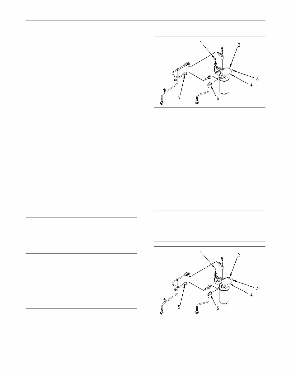
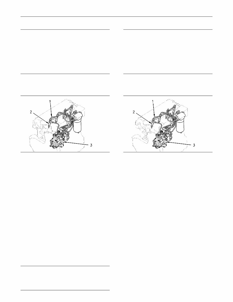
Illustration 1
Typical example
1. Disconnect the tube assembly (5). Disconnect
the tube assembly (6). Install dust covers onto
the connectors for the fuel priming pump.
2. Disconnect the fuel return line from the connector
(3). Install a dust cover to the connector (3).
3. Disconnect the harness assembly from the
connector (2).
4. Support the fuel priming pump. Remove the
three setscrews (1) and discard the rubber
washers. Remove the fuel priming pump (4).
Installation Procedure
NOTICE
Keep all parts clean from contaminants.
Contaminants may cause rapid wear and shortened
component life.
g00952432
Illustration 2
Typical example
1. Clean the external surfaces of the fuel priming
pump (4). Position the fuel priming pump (4) and
install the setscrews (1) and new rubber washers.
5
Disassembly and Assembly Section
2. Remove the dust covers from the fuel priming
pump. Remove the plugs from the tube
assemblies. Connect the tube assembly (5).
Connect the tube assembly (6).
3. Connect the fuel return line to the connector (3).
4. Connect the harness assembly to the connector
(2).
5. Remove the air from the fuel system. Refer to
the Operations and Maintenance Manual, “Fuel
System - Prime”.
i01939067
Fuel Filter Base - Remove and
Install
Removal Procedure
Note: There is an option for the three cylinder
engine. The fuel filter and the fuel priming pump
can be installed onto the application rather than
onto the engine. If this is the case, refer to the
appropriate OEM information as well to this text.
NOTICE
Keep all parts clean from contaminants.
Contaminants may cause rapid wear and shortened
component life.
NOTICE
Care must be taken to ensure that fluids are contained
during performance of inspection, maintenance, test-
ing, adjusting and repair of the product. Be prepared to
collect the fluid with suitable containers before open-
ing any compartment or disassembling any compo-
nent containing fluids.
Dispose of all fluids according to local regulations and
mandates.
Note: The removal procedure is identical for the
four cylinder and the three cylinder engines. The
illustrations show the four cylinder engine.
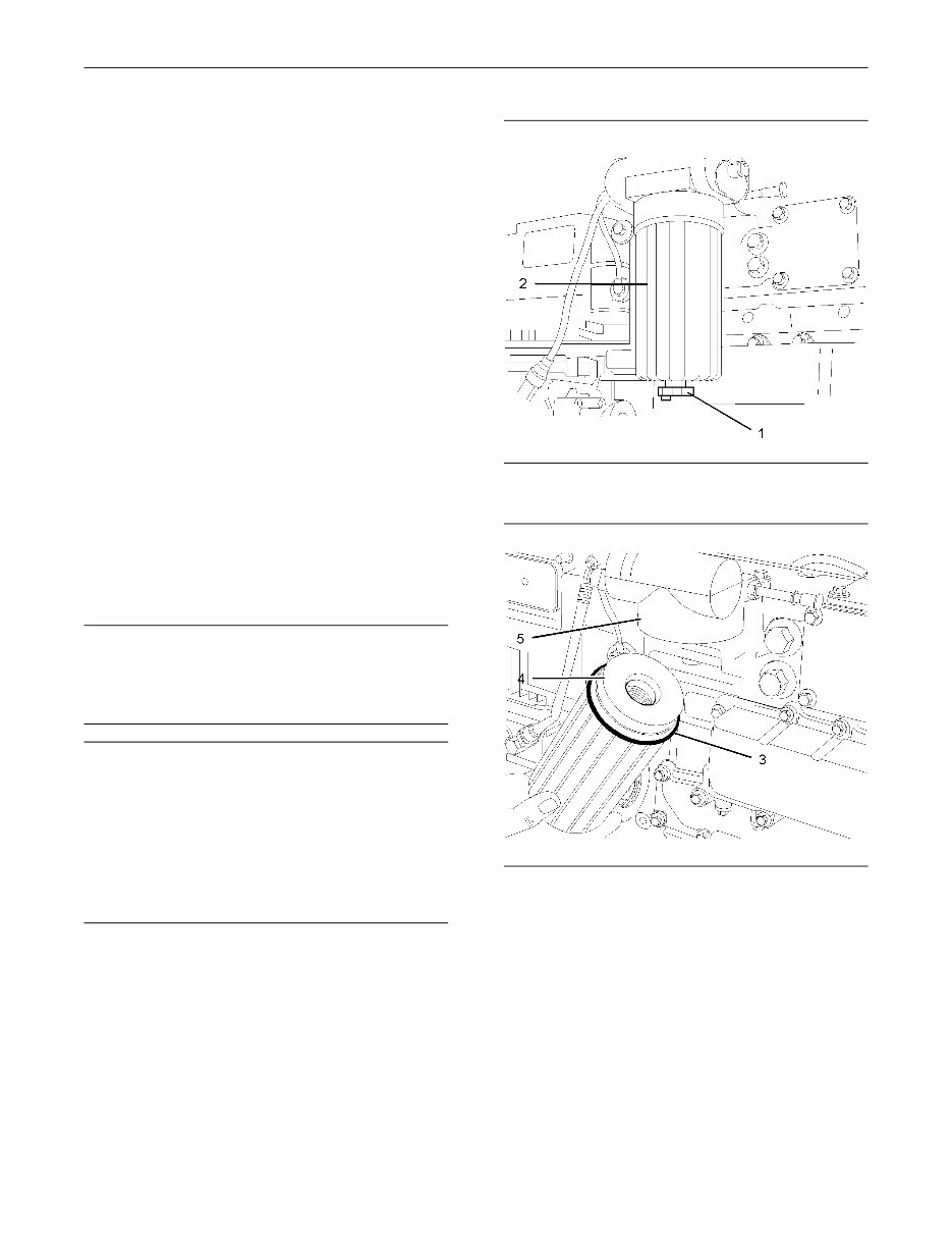
g01010637
Illustration 3
Typical example
g01010595
Illustration 4
Typical example
1. Place a suitable container below the filter in
order to collect the spilled fuel. Thoroughly clean
the outside surfaces of the fuel filter. Open the
drain (1) in order to drain the fuel from the filter.
2. Use a suitable strap wrench to loosen the filter
case (2). Remove the filter case (2) from the filter
head (5).
3. Push down against the spring pressure that is
applied to the filter element (4). Rotate the filter
element (4) counterclockwise in order to release
the filter element from the filter case (2).
4. Discard the filter element (4) and the O-ring (3).
6
Disassembly and Assembly Section
Installation Procedure
NOTICE
Keep all parts clean from contaminants.
Contaminants may cause rapid wear and shortened
component life.
Note: The installation procedure is identical for the
four cylinder and the three cylinder engines. The
illustrations show the four cylinder engine.
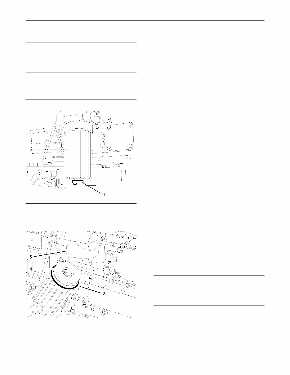
g01010637
Illustration 5
Typical example
g01010595
Illustration 6
Typical example
1. Thoroughly clean the inside of the filter case (2)
and thoroughly clean the lower face of the filter
head (5).
2. Inspect the thread of a new filter element (4) in
order to ensure that the thread is not damaged.
Inspect the thread of the adapter in the filter
head (5) in order to ensure that the thread is not
damaged.
3. Inspect the condition of the spring and ensure
that the spring is correctly located within the
filter case (2).
4. Install the new filter element (4) into the filter
case (2). Push the filter element against the
spring pressure and rotate the filter element in
a clockwise direction in order to secure the filter
element within the filter case (2).
5. Lightly lubricate a new O-ring (3) with clean fuel
oil. Install the new O-ring (3) into the recess
within the filter case (2).
6. Close the drain (1).
7. Remove the air from the fuel system. Refer to
the Operations and Maintenance Manual, “Fuel
System - Prime”. Remove the suitable container
and dispose of the fuel that has drained as
waste.
i01939856
Fuel Injection Lines - Remove
Removal Procedure
Start By:
a. Remove the cover for the fuel injectors. Refer to
this Disassembly and Assembly Manual, “Fuel
Injector Cover - Remove and Install”.
NOTICE
Keep all parts clean from contaminants.
Contaminants may cause rapid wear and shortened
component life.
7
Disassembly and Assembly Section
NOTICE
Care must be taken to ensure that fluids are contained
during performance of inspection, maintenance, test-
ing, adjusting and repair of the product. Be prepared to
collect the fluid with suitable containers before open-
ing any compartment or disassembling any compo-
nent containing fluids.
Dispose of all fluids according to local regulations and
mandates.
Note: The removal procedure is identical for four
cylinder and three cylinder engines. The illustration
shows the four cylinder engine.
g00955826
Illustration 7
Typical example
1. Disconnect the fuel injection lines (1) at the fuel
injectors (2).
2. Disconnect the fuel injection lines (1) at the fuel
injection pump (3).
3. If it is necessary remove the clamps for the fuel
injection lines or loosen the clamps for the fuel
injection lines. Remove the fuel injection lines (1).
4. Install dust caps onto the ports of the fuel
injectors and onto the ports of the fuel injection
pump. Install dust caps onto both ends of the
fuel injection lines.
i01939857
Fuel Injection Lines - Install
Installation Procedure
NOTICE
Keep all parts clean from contaminants.
Contaminants may cause rapid wear and shortened
component life.
NOTICE
Care must be taken to ensure that fluids are contained
during performance of inspection, maintenance, test-
ing, adjusting and repair of the product. Be prepared to
collect the fluid with suitable containers before open-
ing any compartment or disassembling any compo-
nent containing fluids.
Dispose of all fluids according to local regulations and
mandates.
Note: The installation procedure is identical for the
four cylinder and the three cylinder engines. The
illustration shows the four cylinder engine.
g00955826
Illustration 8
Typical example
1. Inspect the fuel injection lines (1) for wear and for
damage. Replace any fuel injection line (1) that
is worn or any fuel injection line that is damaged.
2. Loosely install the clamps for the fuel injection
lines (1).
3. Remove the dust caps from the fuel injection
pump (3) and from the fuel injectors (2). Remove
the dust caps from the fuel injection lines (1).
4. Loosely connect the nuts at both ends of the fuel
injection lines (1).
5. Ensure that each fuel injection line (1) does not
contact any other fuel injection line or any other
engine component. Tighten the fasteners for the
clamps for the fuel injection lines (1). Check that
the fuel injection lines (1) are still clear of other
components.
6. Tighten the fuel injection lines (1) at the fuel
injectors (2) to a torque of 30 N·m (22 lb ft).
7. Tighten the fuel injection lines (1) at the fuel
injection pump (3) to 30 N·m (22 lb ft).
8
Disassembly and Assembly Section
8. Remove the air from the fuel system. Refer to
the Operations and Maintenance Manual, “Fuel
System - Prime”.
End By:
a. Install the cover for the fuel injectors. Refer to
this Disassembly and Assembly Manual, “Fuel
Injector Cover - Remove and Install”.
i01940979
Fuel Injector Cover - Remove
and Install
Removal Procedure
NOTICE
Keep all parts clean from contaminants.
Contaminants may cause rapid wear and shortened
component life.
Note: The removal procedure is identical for the
four cylinder and the three cylinder engines. The
illustration shows the four cylinder engine.
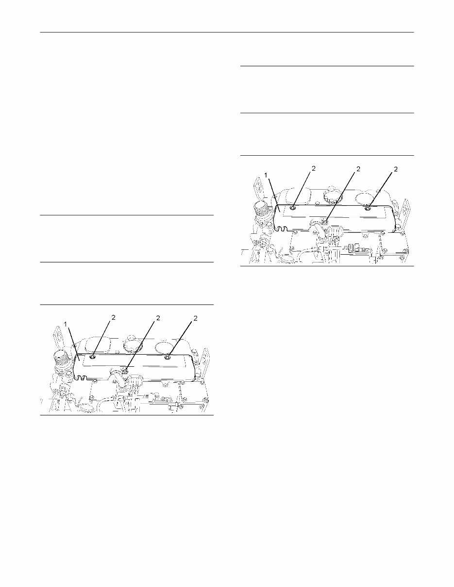
g01011111
Illustration 9
Typical example
1. Thoroughly clean all of the outer surfaces of the
cover (1) for the fuel injectors.
2. Remove the setscrews (2) from the cover (1).
3. Remove the cover (1).
Installation Procedure
NOTICE
Keep all parts clean from contaminants.
Contaminants may cause rapid wear and shortened
component life.
Note: The installation procedure is identical for the
four cylinder and the three cylinder engines. The
illustration shows the four cylinder engine.
g01011111
Illustration 10
Typical example
1. Thoroughly clean all of the inner surfaces of the
cover (1) for the fuel injectors.
2. Install the cover (1).
3. Install the setscrews (2) for the cover (1). Tighten
the setscrews (2) to a torque of 9 N·m (7 lb ft).
i01940997
Fuel Injection Pump - Remove
(Delphi DP210)
Removal Procedure
Start By:
a. Remove the fuel injection lines. Refer to this
Disassembly and Assembly Manual, “Fuel
Injection Lines - Remove”.
b. Remove the crankshaft pulley. Refer to this
Disassembly and Assembly Manual, “Crankshaft
Pulley - Remove and Install”.
9
Disassembly and Assembly Section
c. Remove the front cover. Refer to this Disassembly
and Assembly Manual, “Front Cover - Remove
and Install”.
Note: The removal procedure is identical for the
four cylinder and the three cylinder engines. The
illustrations show the four cylinder engine.
NOTICE
Keep all parts clean from contaminants.
Contaminants may cause rapid wear and shortened
component life.
1. Ensure that the No. 1 cylinder is at top dead
center on the compression stroke. Refer to the
Testing and Adjusting Manual, “Finding Top
Center Position for No. 1 Piston”.
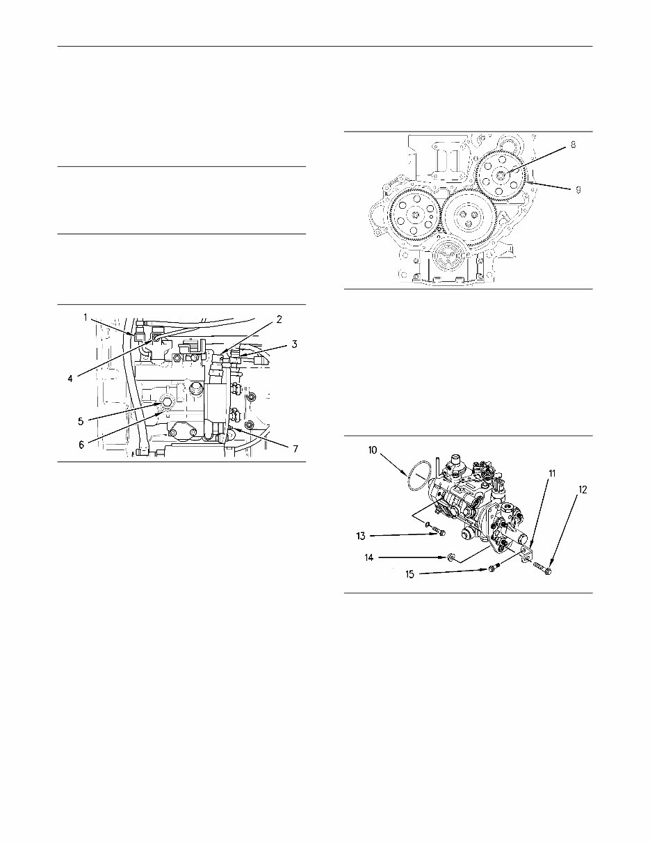
g00956204
Illustration 11
Typical example
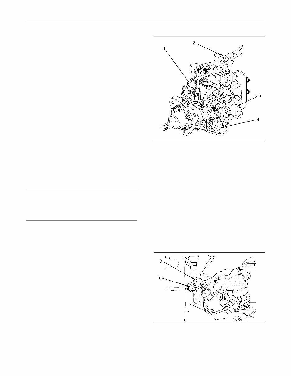
2. Loosen the locking screw (5). Rotate the spacer
(6) in order to allow the locking screw (5) to
tighten against the shaft of the fuel injection
pump. Rotate the fuel injection pump gear in a
counterclockwise direction in order to remove
the backlash. Tighten the locking screw (5) to a
torque of 17 N·m (13 lb ft).
Note: The locking screw (5) must be tightened in
order to prevent the shaft of the fuel injection pump
from rotating. The shaft of the fuel injection pump
must not be rotated after the fuel injection pump
has been removed from the engine.
Note: Put identification marks on all fuel hose
assemblies and on all tube assemblies for
installation purposes. After being disconnected,
plug all fuel hose assemblies and plug all tube
assemblies with suitable plastic plugs. Also install
dust caps on all of the connectors on the fuel
injection pump. This helps prevent fluid loss, and
this helps to keep contaminants from entering the
system.
3. Disconnect the fuel return line (1). Disconnect the
tube assembly (4) from the fuel injection pump.
4. Disconnect the fuel line (3).
5. Disconnect the harness assembly (2) from the
timing advance solenoid (7).
g01011369
Illustration 12
Typical example
6. Remove the nut (8) and the washer from the
shaft of the fuel injection pump.
7. Use a suitable puller in order to remove the fuel
injection pump gear (9).
Note: Do not pry the fuel injection pump gear (9)
from the shaft of the fuel injection pump.
g00956267
Illustration 13
8. Remove the nut (14). Remove the bolt (12).
9. If necessary, remove the setscrew (15) and the
bracket (11) from the cylinder block.
10. Remove the setscrews (13) in order to remove
the fuel injection pump.
11. Remove the fuel injection pump from the front
housing. Remove the O-ring (10) and discard the
O-ring from the fuel injection pump.
10
Disassembly and Assembly Section
i01941022
Fuel Injection Pump - Remove
(Bosch EPVE for the 1104
engines only)
Removal Procedure
Start By:
a. Remove the fuel injection lines. Refer to this
Disassembly and Assembly Manual, “Fuel
Injection Lines - Remove and Install”.
b. Remove the crankshaft pulley. Refer to this
Disassembly and Assembly Manual, “Crankshaft
Pulley - Remove and Install”.
c. Remove the front cover. Refer to this Disassembly
and Assembly Manual, “Front Cover - Remove
and Install”.
NOTICE
Keep all parts clean from contaminants.
Contaminants may cause rapid wear and shortened
component life.
1. Ensure that the No. 1 cylinder is at top dead
center on the compression stroke. Refer to the
Testing and Adjusting Manual, “Finding Top
Center Position for No. 1 Piston”.
g00996409
Illustration 14
Note: Put identification marks on all fuel hose
assemblies and on all tube assemblies for
installation purposes. After being disconnected,
plug all fuel hose assemblies and plug all tube
assemblies with suitable plastic plugs. Also install
dust caps on all of the connectors on the fuel
injection pump. This helps prevent fluid loss, and
this helps to keep contaminants from entering the
system.
2. Disconnect the tube assembly (1) from the fuel
injection pump. Disconnect the tube assembly
(2) from the fuel injection pump.
3. Disconnect the wiring harness assembly from
the cold start advance unit (3). Disconnect the
wiring harness assembly from the engine shutoff
solenoid (4).
g00996410
Illustration 15
You're Reading a Preview
What's Included?
Fast Download Speeds
Offline Viewing
Access Contents & Bookmarks
Full Search Facility
Print one or all pages of your manual
$37.99
Viewed 81 Times Today


Secure transaction
What's Included?
Fast Download Speeds
Offline Viewing
Access Contents & Bookmarks
Full Search Facility
Print one or all pages of your manual
$37.99
This collection includes the following 4 manuals:
- Perkins 1103 and 1104,2490/1500 specification manual
- Perkins 1103 and 1104E disassembly and assembly manual. This is the factory manual 136 pages.
- DC11-Up (Machine)
- DD11-Up (Machine)
- DJ11-Up (Machine)
- DK11-Up (Machine)
- RE11-Up (Machine)
- RG11-Up (Machine)
- RJ11-Up (Machine)
- RR11-Up (Machine)
- RS11-Up (Machine)
- DF11-Up (Engine)
- DG11-Up (Engine)
- Perkins 1103,1104E operation and maintenance manual.
- DC (Engine)
- DD (Engine)
- DJ (Engine)
- DK (Engine)
- RE (Engine)
- RG (Engine)
- RJ (Engine)
- RR (Engine)
- RS (Engine)
- RT (Engine)
- DF (Engine)
- DG (Engine)
- Perkins 1103A-33T parts book, s/n up to U3200321W


