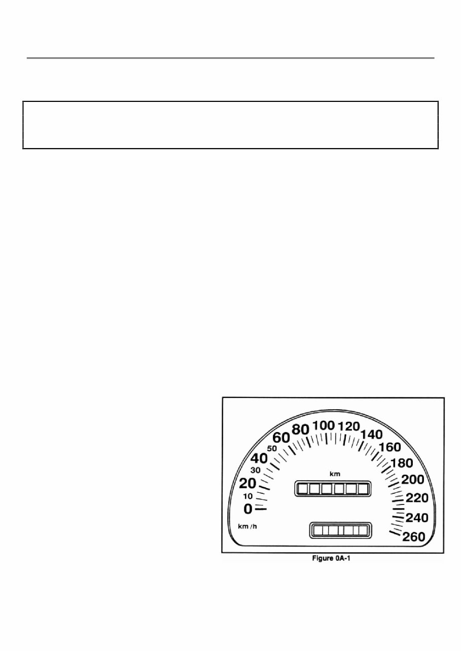
GENERAL INFORMATION OA-1 SECTION 0A CAUTION: This vehicle Is equipped with an AIR BAG. Refer to CAUTIONS, Section 12, In this Volume of the Preliminary Service Information before performing any service operation on or around Air Bag components, the steering mechanism or wiring. Failure to follow the CAUTIONS could result in air bag deployment, resulting In possible personal Injury or unnecessary SRS system repairs. GENERAL INFORMATION CONTENTS Ref. Subject Page 1. GENERAL INFORMATION OA-1 1.1 PRINCIPLE FEATURES OF THE CALIBRA TURBO 4X4 OA-1 Seats and Associated Items OA-1 Instruments . OA-1 Air Bag OA-2 Road heels OA-2 Brakes OA-2 DOHC Turbo Engine OA-3 Clutch/Flywheel OA-4 Manual Transmission OA-5 Transfer Box OA-6 Propeller Shaft OA-7 Exhaust System OA-7 1. GENERAL INFORMATION The introduction of the four wheel drive Calibra Turbo is the first Holden production vehicle that is equipped with four wheel drive at the factory. This vehicle has a substantial number of changed vehicle specifications when compared to the two wheel drive models. The following provides a summary of these features, while subsequent Sections in this Volume detail more specific information relevant to the engine management system of the new C 20 LET turbocharged engine, and the permanent, four wheel drive system. 1.1 PRINCIPLE FEATURES OF THE CALIBRA 4X4 Seats and Associated Items Calibra 4x4 is fitted with leather trim on the seat covers, door panelling and the rear quarter panelling, as standard fitment. The seats are electrically heated and thermostatically controlled. Instruments While the arrangement of the instruments is the same as previous Calibra models, speedometer operation is now electronic, providing greater accuracy. The scale up to 60 km/h is now spread, providing better driver legibility in the lower speed range and the Calibra Turbo speedometer is now calibrated to a top speed of 260 km/h.
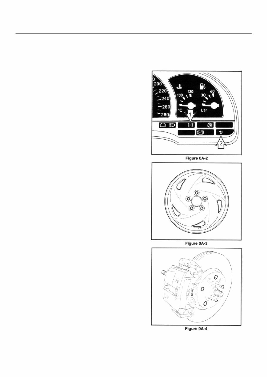
OA-2 GENERAL INFORMATION A four wheel drive telltale lamp for the four wheel drive system in the Calibra Turbo, is now included ('1' in Figure OA-2), that is illuminated continuously or flashes when a system fault has been detected and the normally permanent four wheel drive mode is disengaged. Refer to Section 4 in this Volume for more detailed information. Air Bag All Calibra models are now fitted with a driver’s air bag as standard equipment. Should a fault develop in the air bag s stem, an air bag warning lamp in the instrument pane ('2' in Figure OA-2), will be illuminated. Road Wheels Together with revised design wheel hubs, the Calibra 4x4 is fined with 5 hole, 6J x 16, light alloy disc wheels with a rim offset of 49 mm. These wheels are fitted with 205/50 ZR 16 tyres as standard. Note that snow chains are not to be fitted to these tyre and wheel assemblies. Rear wheel hubs are also drilled to accommodate the new road wheels. Brakes The front brakes on the Calibra Turbo, feature a revised design, single piston, front brake caliper with a piston diameter of 54 mm, with ventilated discs of 284 mm diameter. The rear brakes retain the fixed caliper, two 33 mm piston design, fitted to solid discs of 270 mm. The brake master cylinder has an increased bore size that changes from 22.2 mm to 23.8 mm to correspond to the increased diameter calipers fitted to the front brakes.
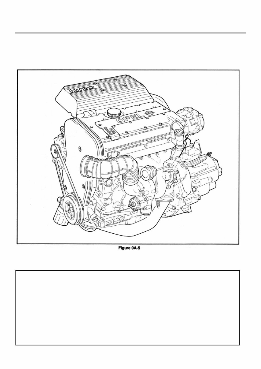
GENERAL INFORMATION OA-3 DOHC Turbo Engine The new 2 litre, 16 valve C 20 LET engine features a new integral turbocharger system with intake charge cooling and sequential fuel infection and knock control and is based on the existing C 20 XE engine. The engine management system used, is the Motronic 2.7, that is also used to control the intake charge pressure. For a more detailed explanation of the engine management system, refer to Section 6C in this Volume. Engine Data - C 20 LET Displacement . ................................................................................................................................................................ 1,998 cm Bore diameter . ................................................................................................................................................................ 86.0 mm Stroke .............................................................................................................................................................................. 86.0 mm Valve Diameter - Inlet . ............................................................................................................................................................................. 33.0 mm - Exhaust ......................................................................................................................................................................... 29.0 mm Valve Stroke . .................................................................................................................................................................. 8.5 mm Output at Engine Speed . ................................................................................................................................................ 150 kW @ 5,600 rpm Maximum Torque at Engine Speed ................................................................................................................................ 280 Nm @ 2,400 rpm Compression ratio .......................................................................................................................................................... 9.0 : 1 Spark Plugs . ................................................................................................................................................................... FR 7 LC 2 Engine Management with Knock Control and Charge Pressure Control ....................................................................... Motronic M 2.7 Fuel . ............................................................................................................................................................................... Unleaded 91 octane
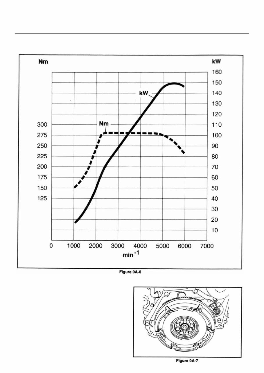
OA-4 GENERAL INFORMATION Power and Torque Curves Clutch/Flywheel The clutch has been adapted to suit the increase in engine torque. This has been achieved by increasing the driven plate surface area and increasing the force applied by the Belleville spring in the pressure plate. As a general design change, the flywheel used on all Calibra engines is now of the 'pot' design. This change results in a higher mass moment of inertia that contributes to smoother running and a reduction in transmission gear rollover rattle. This now means that the clutch can be replaced only when the transmission has been removed.
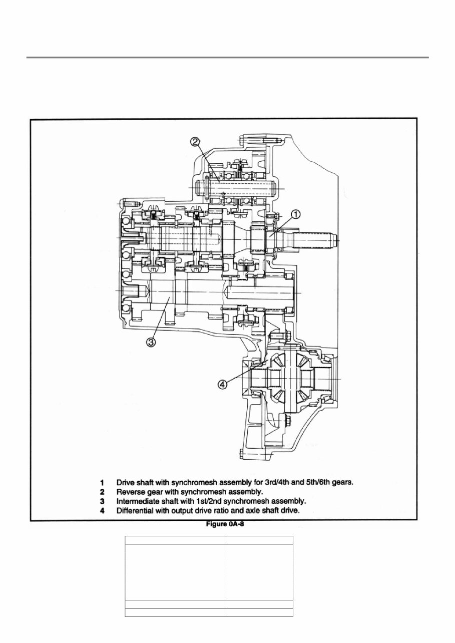
GENERAL INFORMATION OA-5 Manual Transmission The Calibre Turbo is fitted with a newly developed, compact, fully synchronized, 6-speed manual transmission. Known as the F 28/6, the extra sixth gear, results in low engine speed at high road speeds, providing high engine torque and low fuel consumption. Essentially, there are no serviceable components within the transmission. Gear Selected Ratio :1 1 3.57 2 2.13 3 1.46 4 1.10 5 0.89 6 0.74 Reverse 3.32 Front Output Drive Axle 3.72 Gear Ratios Rear Output Drive Axle 3.70
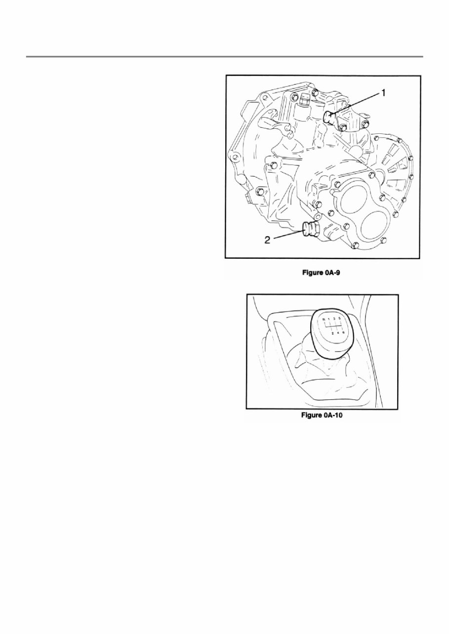
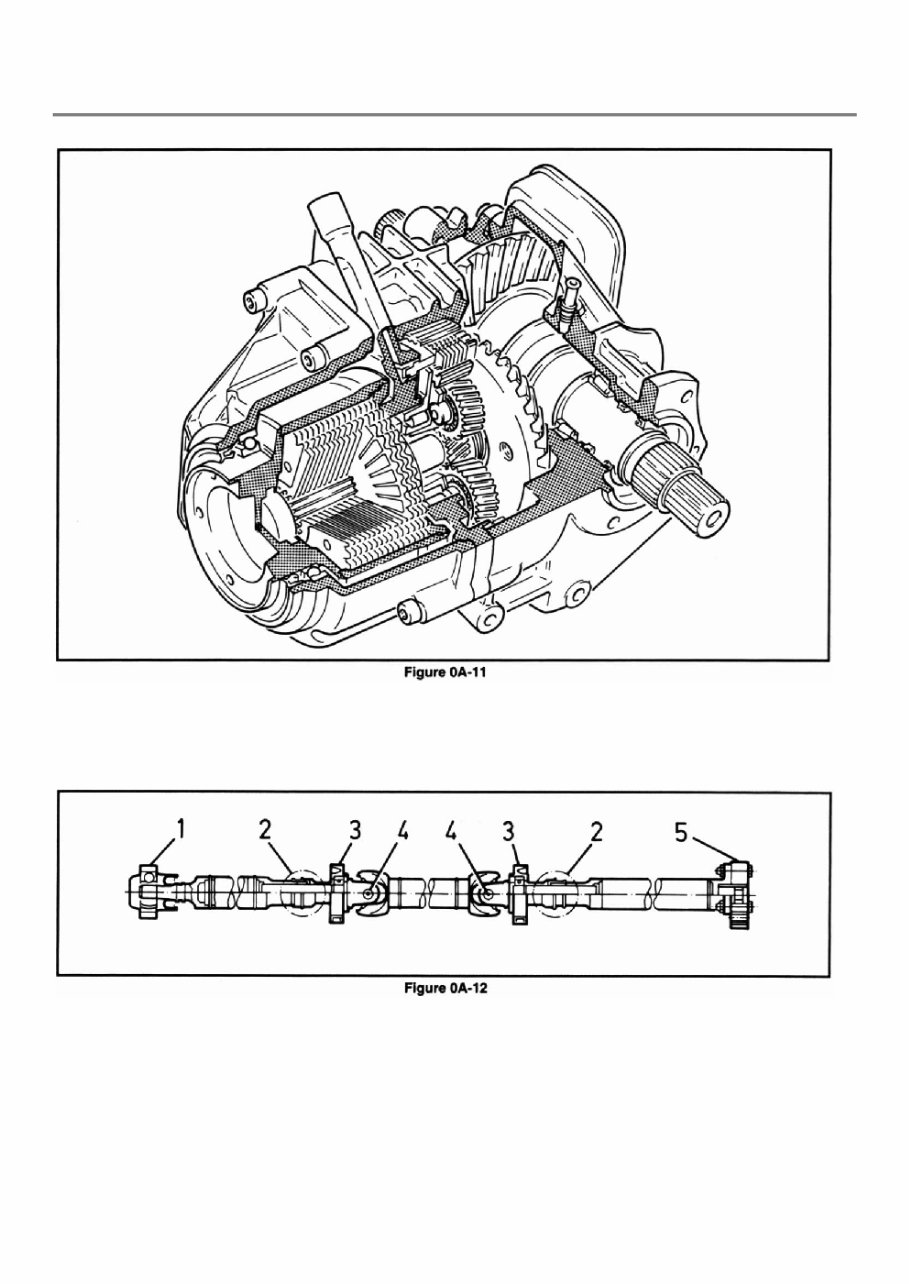
OA-6 GENERAL INFORMATION Sensing Switches In the transmission housing, in addition to the speedometer drive and reversing lamp switches, a first gear switch is also fitted. Both the reverse and first gear switch signals are used by the Motronic M 2.7, to disengage turbo boost when either starting from rest in first or reverse gear, to minimise the possibility of a loss of control of the vehicle, in these operating modes. Refer to Section 6C ENGINE MANAGEMENT in this Volume for more information relating to these switch functions. Shift Lever The shift selection arrangement on the leather covered shift knob has been changed to show the 6 speed ranges and reverse. Transfer Box The engine torque to the rear axle is transferred to the hypoid gear in the transfer box, via a hollow shaft, which is connected to the transmission and this diverts the power flow through 90°. The torque flows to the viscous coupling via a secondary planetary gear, comprising a ring gear, planet gears and sun gear. The outer housing of the viscous coupling is connected to the rear propeller shaft. A mufti-disc clutch plate controls the operation of the planetary gear set, with the inner discs being splined to the ring gear and the outer discs, to the outer housing. When the apply fluid pressure builds up from 3,600 -5,200 kPa, the clutch apply piston compresses the clutch pack, effectively locking the ring gear of the planetary gear set to the outer transfer box housing. This action engages four wheel drive operation. When the apply fluid pressure drops below a pre-set value, a spring pushes the apply piston back, releasing the clutch pack, thereby freeing the planetary gear set. When this occurs, four wheel drive operation ceases. For information relating to the servicing of the transfer box, refer to page K-176 in Volume 2 of the Vectra, Cavalier, Calibra Service Instructions (PM M403278).
GENERAL INFORMATION OA-7 Propeller Shaft With the independent rear suspension, movement by the road wheels during compression and rebound, results in undesirable motions for the smooth transmission of power to the rear wheels. The effect of these motions has been overcome by using a rear propeller shaft comprised of a number of different components, as indicated in Figure OA-12. Illustration Key 1 Homokinetic joint, front 4 Universal joint 2 Front and rear sliding gears with locking nut 5 Single disc joint, rear 3 Front and rear centre bearings Exhaust System The Calibra Turbo vehicle uses an exhaust system that has several special features, compared to the two wheel drive vehicle: - - The combination of the fantail manifold and front exhaust pipe are no longer used. - - Exhaust gases are now collected behind the turbocharger and passed through to the exhaust system in a short baffle manifold, that is fitted with a spherical graphite seal ring, which effectively reduces vibration transfer. The pipe diameter used for this engine is 60 mm.
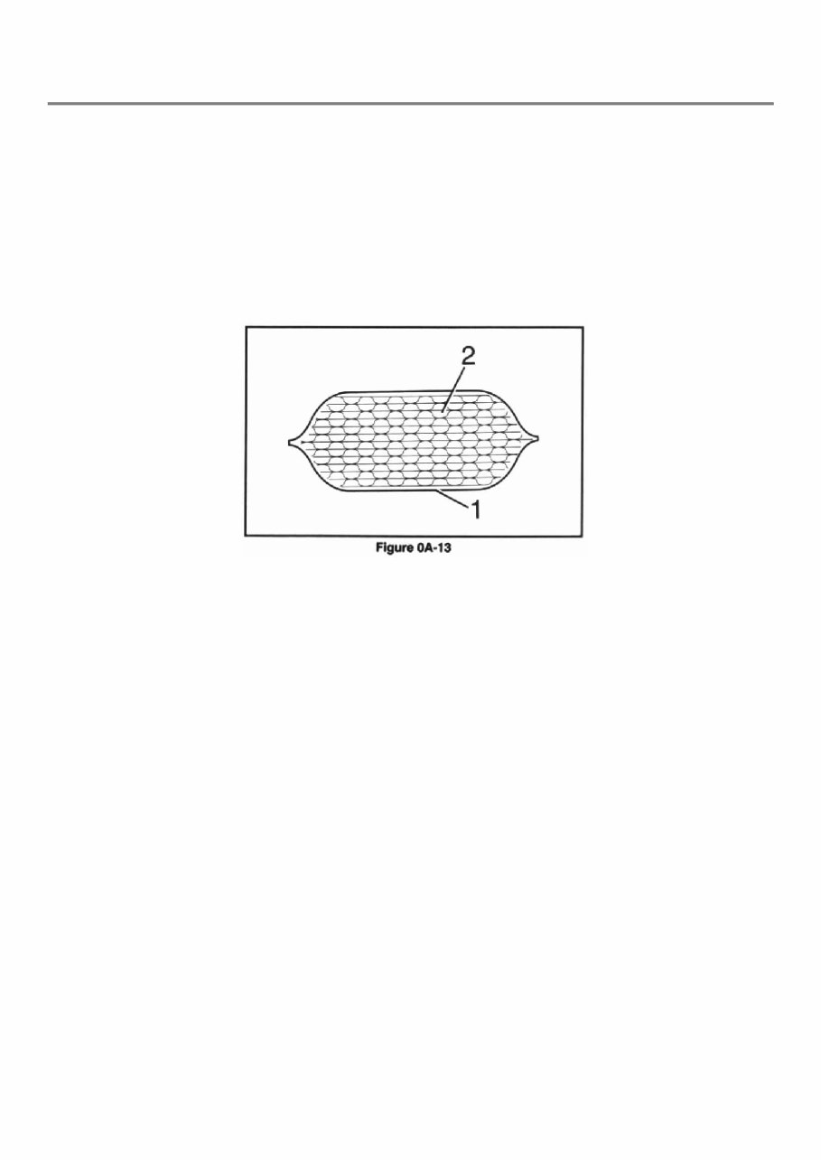
OA-8 GENERAL INFORMATION - - The front muffler is of an absorption design, while the rear muffler is constructed for reflection and absorption. - - The entire exhaust system is also made from stainless steel, to improve life. - - The catalytic converter has a larger, effective catalytic surface and to achieve the same outer dimensions, a metal construction has been adopted. Instead of the more conventional ceramic converter, a backing is processed from metal for the platinum/rhodium coating. This results in: - - Low dynamic pressure. - - Operating temperatures are reached more quickly - - An extremely effective conversion (more than 90%) of noxious substances. Illustration Key: 1. Stainless steel housing. 2. Metal backing with platinum/rhodium coating. For more detailed information relating to the turbocharger and associated controls, refer to Section 6A, ENGINE MECHANICAL in this Volume.
FOUR-WHEEL DRIVE SYSTEM 4-1 SECTION 4 CAUTION: This vehicle Is equipped with an AIR BAG. Refer to CAUTIONS, Section 12, In this Volume of the Preliminary Service Information before performing any service operation on or around Air Bag components, the steering mechanism or wiring. Failure to follow the CAUTIONS could result In air bag deployment, resulting In possible personal Injury or unnecessary SRS system repairs. FOUR-WHEEL DRIVE SYSTEM CONTENTS Ref Subject Page Ref Subject Page 1. GENERAL INFORMATION .................................................... 4-1 3.1 SERVICE TIPS.............................................................. 4-17 The Four-Wheel Drive Function ........................................... 4-2 Rear Axle ...................................................................... 4-17 Braking Safety ....................................................................... 4-3 Driveline ....................................................................... 4-17 Other Four-Wheel Drive Features ........................................ 4-3 System Isolation .......................................................... 4-17 2. COMPONENTS OF THE FOUR-WHEEL DRIVE SYSTEM 4-5 Transmission/Transfer Box Overhaul ....................... 4-17 2.1 MECHANICAL, HYDRAULIC ................................................. 4-5 Extract from the Wiring Diagram ............................... 4-18 Transfer Box .......................................................................... 4-5 Terminal Assignment of Wiring Hydraulic System for Four-Wheel Drive Disengagement ... 4-8 Harness Plug for E C U ............................................... 4-19 Rear Axle, Rear Axle Mounting ............................................ 4-10 Diagnostic Trouble Codes .......................................... 4-19 Driveshaft ............................................................................... 4-11 4. DIAGNOSIS .................................................................. 4-20 2.2 ELECTRONIC, ELECTRICAL ................................................ 4-12 Introduction ................................................................. 4-20 Block Diagram of Electronics .............................................. 4-12 General Instructions/Safety Measures ...................... 4-20 Survey of Four-Wheel Drive System .................................... 4-13 Checking With TECH 1................................................ 4-20 3. SERVICE OPERATIONS ........................................................ 4-16 4.1 TROUBLE CODE TABLE............................................. 4-21 Hydraulic Fluid Level Control .............................................. 4-16 4.2 F0: DATA LIST - Quick Check .................................... 4-26 System Bleeding ................................................................... 4-16 4.3 F5: ACTUATOR TEST.................................................. 4-28 Transfer Box Maintenance ................................................... 4-16 5. SPECIFICATIONS ........................................................ 4-29 6. SPECIAL TOOLS ......................................................... 4-30 1. GENERAL INFORMATION The Calibra Turbo 4x4 is equipped with a permanent four-wheel drive system; i.e. always engaged. The drive forces are distributed to the front and rear axles by a non-wearing fluid coupling (viscous coupling) integrated into the transfer box. The amount of power transmitted to the rear wheels varies according to requirement as a result of the difference in speed between the front and rear axles. A new feature in four-wheel drive technology is that, on braking at a speed over 25 km/h, the drive train is disengaged by a hydraulically controlled multi-disc plate and the four-wheel drive is switched off. The advantages of four-wheel drive are: a. Good driving even on slippery roads. b. Low slip when accelerating. c. Increased climbing ability on slippery surfaces.
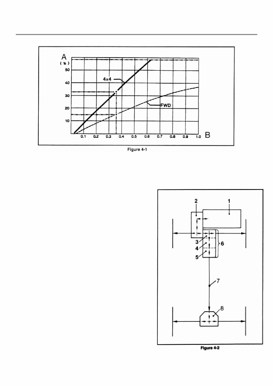
4-2 FOUR-WHEEL DRIVE SYSTEM Figure 4-1 Figure 4-1 shows the climbing ability (A) at a certain frictional coefficient (B) for a four-wheel drive and for a normal front wheel drive. The constant four-wheel drive substantially increases driving and traction forces. The advantages of this can be noticed particularly when starting from rest and driving on difficult terrain such as unsealed roads or surfaces that have been made slippery by ice and snow. Driving under these road conditions presents few problems in terms of becoming bogged or losing traction, as the four-wheel drive function allows normal driving regardless of the road conditions. When braking, the same need for care applies as with a normal front wheel drive vehicle. THE FOUR-WHEEL DRIVE FUNCTION Engine, clutch and transmission form a unit, as in standard vehicles, and drive the front wheels. The rear wheels are driven fully automatically via: – – The transfer box (6) which is flanged onto the right hand side of the transmission and has an integrated viscous coupling and four-wheel drive cut-off, – – A three part drive shaft (7) and, – – The rear axle and differential assembly (8). The four-wheel drive is permanently and automatically effective - without any interaction required by the driver. Primarily it is the front axle that is driven but the amount of power transferred to the rear axle is changed by the viscous coupling as required, up to almost 100%. Because it is always engaged, the viscous coupling compensates when there is a difference in speed between the drive axles. Engine torque is therefore distributed according to the frictional relationships of the road surface. Illustration Key: 1. 1. Engine. 2. 2. Clutch, Transmission, Front Drive Axle and Differential, Front Wheels. 3. 3. Angle Drive with Hypoid Gear Teeth. 4. 4. Planetary Gear and Multi-Disc Clutch. 5. 5. Viscous Coupling. 6. 6. Transfer Box. 7. 7. Drive Shaft. 8. 8.
This technical manual provides comprehensive service, maintenance, troubleshooting, and replacement procedures for the Opel C20LET 2.0L engine. It includes step-by-step instructions, clear images, and exploded-view illustrations, making it valuable for both professional mechanics and DIY enthusiasts.
The manual offers manufacturer-sourced procedures that are easy to understand and implement, enabling safe and efficient engine servicing and repair. It covers troubleshooting and replacement procedures with detailed instructions, torque specs, and clear images, facilitating quick diagnosis, repair, or overhaul of the engine.
With this manual, specific information can be easily located without the hassle of flipping through numerous pages. It provides a convenient digital format that allows for easy access, search, screenshot, and bookmark functions, offering advantages over traditional bound manuals. Additionally, it is printable for those who prefer physical copies.
Printable: Yes
Language: English
Compatibility: Compatible with various electronic devices, including PC, Mac computers, Android and Apple smartphones, and tablets