



ONAN TORO POWER PLUS P216, 18, 20, 24 ENGINES - HORIZONTAL
Table of Contents – Page 1 of 2
SAFETY PRECAUTIONS
GENERAL
PROTECT AGAINST MOVING PARTS
BATTERIES
FUEL SYSTEM
EXHAUST SYSTEM
EXHAUST GAS IS DEADLY!
COOLING SYSTEM
KEEP THE UNIT AND SURROUNDING AREA CLEAN
CAUTION
GENERAL INFORMATION
INTRODUCTION
ENGINE MODEL REFERENCE
SPECIFICATIONS
DIMENSIONS AND CLEARANCES
P216, P218, P220
P216,P218,P220
P224
P224
ASSEMBLY TORQUES
SPECIAL TOOLS
ENGINE TROUBLESHOOTING
OIL SYSTEM
CRANKCASE OIL
OIL FILTER CHANGE
CRANKCASE BREATHER
CRANKCASE BREATHER SERVICE
P216, P218, P220
P224
PRESSURE LUBRICATION
OIL PUMP
OIL BYPASS VALVE
FUEL SYSTEM
CARBURETOR
CARBURETOR SPEED SETTINGS
CARBURETOR OVERHAUL
REMOVAL
DISASSEMBLY
CLEANING AND REPAIR
REASSEMBLY AND INSTALLATION
PULSATING-DIAPHRAGM FUEL PUMP
FUEL PUMP TEST PROCEDURE
PURPOSE
CARBURETOR (BEGINNING SPEC G)
CARBURETOR HIGH-ALTITUDE JET (OPTIONAL)
AIR CLEANER
GOVERNOR SENSITIVITY

ONAN TORO POWER PLUS P216, 18, 20, 24 ENGINES - HORIZONTAL
Table of Contents – Page 2 of 2
IGNITION AND BATTERY CHARGING
IGNITION SYSTEM DESCRIPTION
IGNITION TIMING
CONTINUITY TEST
IGNITION COIL
SPARK PLUGS
BATTERY INSPECTION
BATTERY JUMP STARTING
FLYWHEEL ALTERNATOR
ALTERNATOR OUTPUT TEST
TYPICAL WIRING DIAGRAM
STARTING SYSYTEM
ELECTRIC STARTER
SERVICE
STARTER REMOVAL
STARTER DISASSEMBLY
STARTER ASSEMBLY
INSPECTION AND TESTING
STARTER MOUNTING
ENGINE DISASSEMBLY
DISASSEMBLY/ASSEMBLY
SUGGESTED DISASSEMBLY ORDER
SUGGESTED ASSEMBLY PROCEDURE
OPERATION
TESTING COMPRESSION
TAPPET ADJUSTMENT
VALVE SYSTEM
INSPECTION
TAPPETS
VALVE FACE AND SEAT GRINDING
FLYWHEEL
GEAR COVER
GOVERNOR CUP
TIMING GEARS
PISTONS AND CONNECTING RODS
CYLINDER BLOCK
CLEANING
INSPECTION
REBORING THE CYLINDER
HONING CYLINDERS (USING PRECISION HONES)
DEGLAZING CYLINDER BORES
CRANKSHAFT
BEARINGS
CRANKSHAFT ENDPLAY
CHECKING CONNECTING ROD BEARING CLEARANCE WITH PLASTIGAUGE
OIL SEALS
PISTON ASSEMBLY
INSTALLATION OF PISTON IN CYLINDER
CYLINDER HEADS
P216, P218, P220 INSTALLATION
224 INSTALLATION
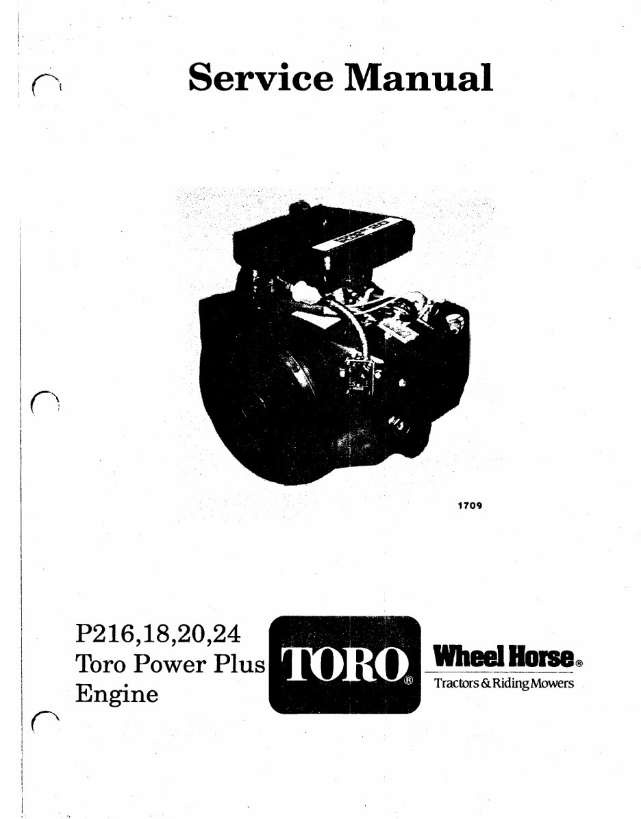
Service Manual
1709
P216,18,20,24
TORO Power Plus
Engine
Tractors & Riding Mowers
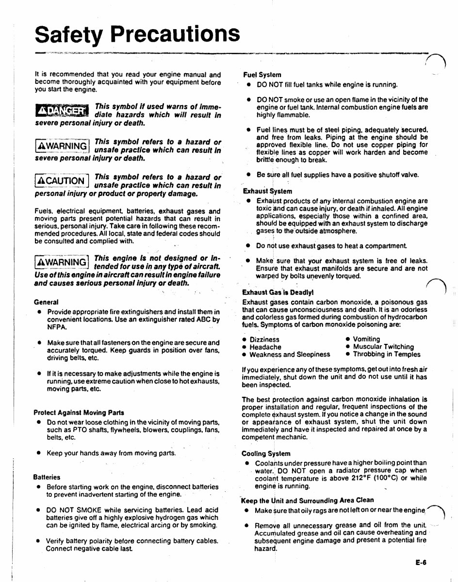
Safety Precautions
It is recommended that you read your engine manual and
become thoroughly acquainted with your equipment before
you start the engine.
This symbol if used warns of imme-
diate hazards which will result in
severe personal injury or death.
Thissymbolreferstoahazardor
unsafe practice which can result In
severe personal injury or death.
Thissymbolrefersto a hazard or
unsafe practice which can result in
personal injury or product or property damage.
Fuels, electrical equipment batteries, exhaust gases and
movingpartspresentpotentialhazardsthat can result in
serious, personal injury. Take care in following these recom-
mended procedures. All local. state and federal codes should
be consulted and complied with.
This engine is not designed or In-
tended for use in any type of aircraft.
Use of this engine in aircraft can result in engine failure
and causes serious personal injury or death.
General
Provide appropriate fire extinguishers and install them in
convenient locations. Use an extinguisher rated ABC by
NFPA.
Make sure that all fasteners on the engine are secure and
accurately torqued. Keep guards in position over fans,
driving belts, etc.
If it is necessary to make adjustments while the engine is
running, use extreme caution when close to hot exhausts,
moving parts. etc.
Protect Against Moving Parts
Do not wear loose clothing in the vicinity of moving parts.
such as PTO shafts, flywheels, blowers, couplings, fans,
belts, etc.
Keep your hands away from moving parts.
Batteries
Before starting work on the engine. disconnect batteries
to prevent inadvertent starting of the engine.
DO NOT SMOKE whileservicingbatteries.Leadacid
batteries give off a highly explosive hydrogen gas which
can be ignited by flame, electrical arcing or by smoking.
Verify battery polarity before connecting battery cables.
Connect negative cable last.
Fuel System
DO NOT fill fuel tanks while engine is running.
DO NOT smoke or use an open flame in the vicinity of the
engine or fuel tank. Internal combustion engine fuels are
highly flammable.
Fuel lines must be of steel piping, adequately secured,
andfreefromleaks.Pipingattheengineshouldbe
approved flexible line., Do not use copper piping for
flexible lines as copper will work harden and become
brittle enough to break.
Be sure all fuel supplies have a positive shutoff valve.
Exhaust System
Exhaust products of any internal combustion engine are
toxic and can cause injury, or death if inhaled. All engine
applications,especiallythosewithinaconfinedarea,
should be equipped with an exhaust system to discharge
gases to the outside atmosphere.
Do not use exhaust gases to heat a compartment
Make' sure that your exhaust system is free of leaks.
Ensure that exhaust manifolds are secure and are not
warped by bolts unevenly torqued.
Exhaust Gas is Deadly!
Exhaust gases contain carbon monoxide, a poisonous gas
that can cause unconsciousness and death. It is an odorless
and colorless gas formed during combustion of hydrocarbon
fuels. Symptoms of carbon monoxide poisoning are:
Dizziness Vomiting
Headache Muscular Twitching
Weakness and Sleepiness Throbbing in Temples
If you experience any of these symptoms. get out into fresh air
immediately, shut down the unit and do not use until it has
been inspected.
The best protection against carbon monoxide inhalation is
proper installation and regular, frequent inspections of the
complete exhaust system. If you notice a change in the sound
or appearance of exhaustsystem,shutthe unitdown
immediately and have it inspected and repaired at once by a
competent mechanic.
Cooling System
Coolants under pressure have a higher boiling point than
water., DO NOT open a radiator pressure cap when
coolant temperature is above 212ºF (100ºC) or while
engine is running.
Keep the Unit and Surrounding Area Clean
Make sure that oily rags are not left on or near the engine,
Remove all unnecessary grease and oil from the unit ~-
Accumulated grease and oil can cause overheating and
subsequent engine damage and present a potential fire
hazard.
E-6
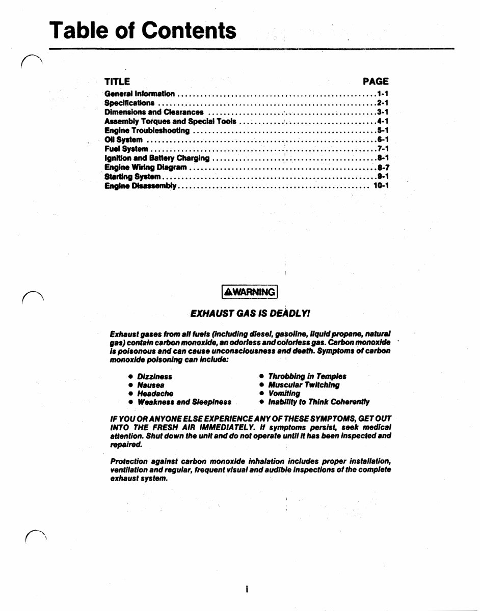
Table of Contents
TITLE PAGE
General Information ................................................... .1-1
Specifications ........................................................ .2-1
Dimensions and Clearances ............................................. .3-1
Assembly Torques and Special Tools .................................... .4-1
Engine Troubleshooting ............................................... .5-1
Fuel System ........................................................... .7-1
Ignition and Battery Charging ........................................... .8-1
Oil System ........................................................... .6-1
Engine Wiring Diagram ................................................ .8-7
Starting System. ...................................................... .9-1
Englne Disassembly... ............................................... 10-1
EXHAUST GAS IS DEADLY!
Exhaust gases from all fuels (Including diesel, gasoline, liquid propane, natural
gas) contain carbon monoxide, an odorless andcolorless gas. Carbon monoxide
is poisonous and can cause unconsciousness and death. Symptoms of carbon
monoxide poisoning can include:
Dizziness Throbbing in Temples
Nausea Muscular Twitching
Headache vomiting
Weakness and Sleepiness Inability to Think Coherently
IF YOU OR ANYONE ELSE EXPERIENCE, ANY OF THESE SYMPTOMS, GET OUT
INTO THE FRESH AIR lMMEDlATELY. If symptoms persist, seek medical
attention. Shut down the unit and do not operate until it has been inspected and
repaired.
Protection against carbon monoxide inhalation includes proper installation,
ventilationand regular, frequent visual and audible inspections of the complete
exhaust system.
General Information
This manual deals with specific mechanical and elec-
trical information needed by engine mechanics for
troubleshooting, servicing, repairing, or overhauling the
engine.
Use the separate PARTS MANUAL for parts identification
and for establishing their proper location on assemblies.
The PARTS MANUAL contains detailed exploded views
of each assembly and the individual piece part numbers
and their proper names for ordering replacement parts.
The illustrations and procedures presented in each
section apply to the engines listed on the cover. The
flywheel-blower end of the engine is the front end so
right and left sides are determined by viewing the engine
from the front. The No. 1 cylinder is on the left, No. 2
cylinder is on the right.
If a major repair or an overhaul is necessary, a competent
-mechanic should either do the job or supervise and
check the work of the mechanic assigned to the job to
ensure that all dimensions, clearances and torque
values are within the specified tolerances.
Use the table of contents for a quick reference to the
separate engine system sections.
The troubleshooting guide is provided as a quick
reference for locating and correcting engine trouble.
The wiring diagram shows how the electrical compo-
nents are interconnected.
The disassembly section contains major overhaul
procedures for step by step removal, disassembly,
inspection, repair, and assembly of the engine
components.
Use only Genuine Tom Plower Plus replacement partsto
ensure quality and the best possible repair and overhaul
results. When ordering parts, always use the complete
model and spec number as well as the serial number
shown on the nameplate.
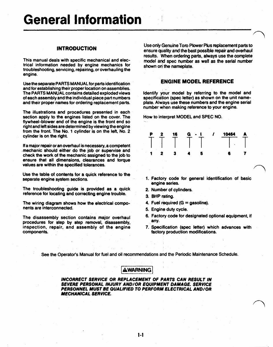
ENGINE MODEL REFERENCE
Identify your model by referring to the model and
specification (spec letter) as shown on the unit name-
plate. Always use these numbers and the engine serial
number when making reference to your engine.
How to interpret MODEL and SPEC NO.
3 6 7
1. Factory codeforgeneralidentificationofbasic
2. Number of cylinders.
4. Fuel required (G = gasoline).
5. Engine duty cycle.
6. Factory code for designated optional equipment, if
7. Specification (spec letter) which advances with
engine series.
3. BHP rating.
any.
factory production modifications.
See the Operator's Manual for fuel and oil recommendations and the Periodic Maintenance Schedule.
INCORRECT SERVICE OR REPLACEMENT OF PARTS CAN RESULT IN
SEVERE PERSONAL INJURY AND/OR EQUIPMENT DAMAGE. SERVICE
PERSONNEL MUST BE QUALIFIED TO PERFORM ELECTRICAL AND/OR
MECHANICAL SERVICE.
1-1
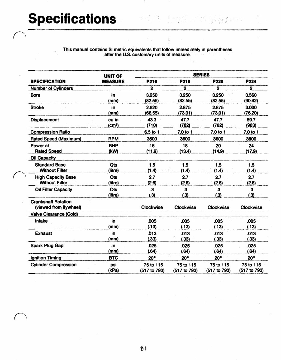
Specifications
This manual contains SI metric equivalents that follow immediately in parentheses
after the U.S. customary units of measure.
2- 1
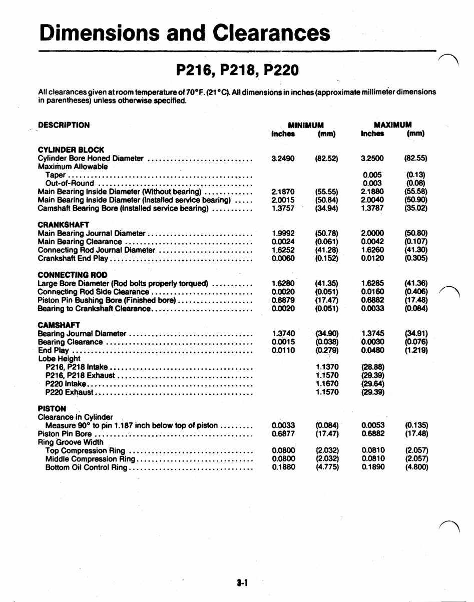
Dimensions and Clearances
P216. P218. P220
All clearances given at room temperature of 70°F . (21°C) . All dimensions in inches (approximate millimeter dimensions
in parentheses) unless otherwise specified .
DESCRIPTION
CYLINDER BLOCK
Cylinder Bore Honed Diameter ............................
Maximum Allowable
Taper .................................................
Out-of-Round .........................................
Main Bearing Inside Diameter (Without bearing) .............
Main Bearing Inside Diameter (Installed service bearing) .....
Camshaft Bearing Bore (Installed service bearing) ...........
CRANKSHAFT
Main Bearing Journal Diameter ............................
Main Bearing Clearance ..................................
Connecting Rod Journal Diameter .........................
Crankshaft End Play ......................................
CONNECTING ROD
Connecting Rod Side Clearance ...........................
Piston Pin Bushing Bore (Finished bore) ....................
Bearing to Crankshaft Clearance ...........................
CAMSHAFT
Bearing Journal Diameter .................................
Bearing Clearance .......................................
End Play ................................................
Lobe Height
P216. P218 Intake ......................................
P216. P218 Exhaust ....................................
P220 Intake ............................................
P220 Exhaust ..........................................
Large Bore Diameter (Rod bolts properly torqued) ...........
PISTON
Clearance in Cylinder
Measure 90° to pin 1.187 inch below top of piston .........
Piston Pin Bore ...........................................
Ring Groove Width
Top Compression Ring .................................
Middle Compression Ring ...............................
Bottom Oil Control Ring .................................
3.2490 (82.52)
2.1870
(55.55)
2.001 5
(50.84)
1.3757
(34.94)
1.9992
(50.78)
0.0024
(0.061)
1.6252
(41.28)
0.0060
(0.1 52)
1.6280 (41.35)
0.0020
(0.051)
0.6879
(1 7.47)
0.0020
(0.051)
1.3740 (34.90)
0.01 10 (0.279)
1.1 370
1.1 570
1.1 670
1.1 570
0.001 5 (0.038)
0.0033 (0.084)
0.6877 (1 7.47)
0.0800 (2.032)
0.0800
(2.032)
0.1 880
(4.775)
3.2500 (82.55)
0.005 (0.1 3)
0.003 (0.08)
2.1 880
(55.58)
2.0040
(50.90)
1.3787
(35.02)
2.0000
(50.80)
0.0042
(0.1 07)
1.6260
(41 30)
0.01 20
(0.305)
1.6285 (41 36)
0.0160 (0.406)
0.6882
(1 7.48)
0.0033
(0.084)
1.3745
(34.91)
0.0030
(0.076)
0.0480
(1.219)
(28.88)
(29.39)
(29.64)
(29.39)
0.0053
(0.1 35)
0.6882
(1 7.48)
0.081 0
(2.057)
0.081 0
(2.057)
0.1 890
(4.800)
3-1
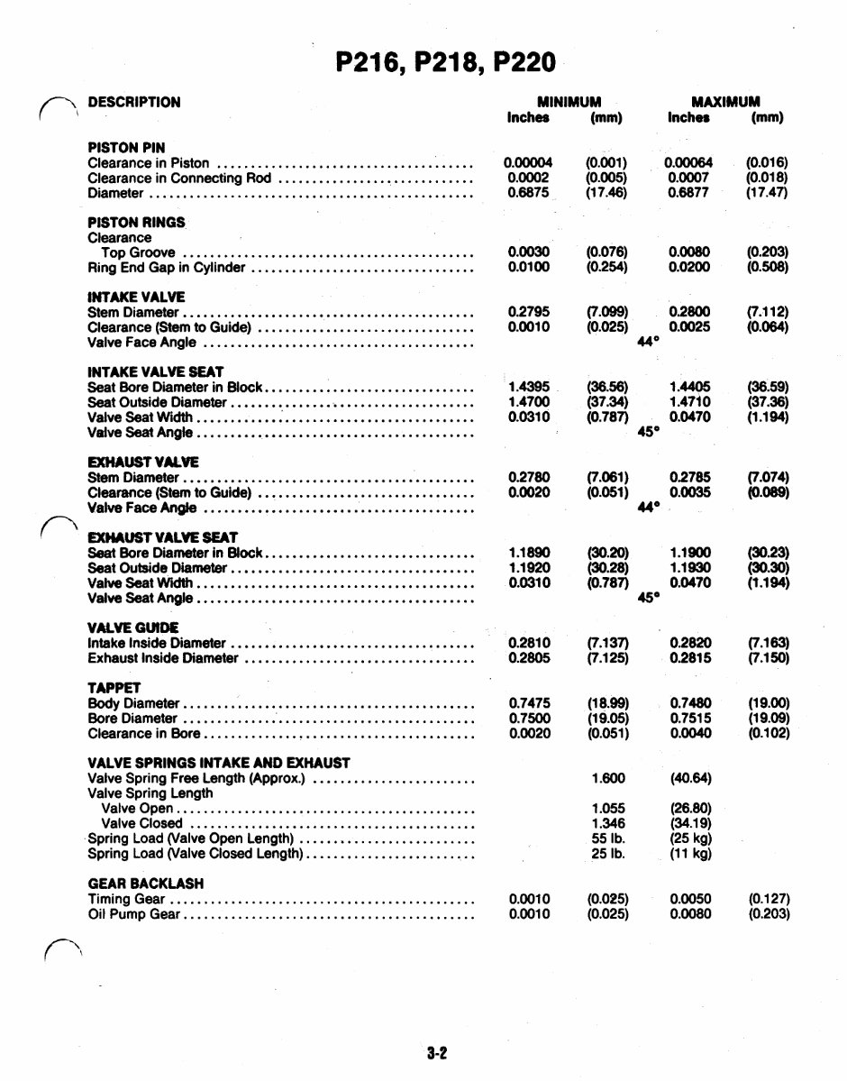
P216. P218. P220
PISTON PIN
Clearance in Piston ......................................
Clearance in Connecting Rod ..............................
Diameter ................................................
PISTON RINGS
Clearance
Top Groove ...........................................
Ring End Gap in Cylinder .................................
INTAKE VALVE
Stem Diameter ...........................................
Clearance (Stem to Guide) ................................
Valve Face Angle ........................................
INTAKE VALVE SEAT
Seat Bore Diameter in Block ...............................
Seat Outside Diameter .....................................
Valve Seat Width .........................................
Valve seat Angle .........................................
EXHAUST VALVE
Stem Diameter ...........................................
Clearance (Stemto Guide) ................................
Valve Face Angle ........................................
EXHAUST VALVE SEAT
Seat Bore Diameter in Block ...............................
Seat Outside Diameter ....................................
Valve Seat Width .........................................
Valve Seat Angle .........................................
VALVE GUIDE
Intake Inside Diameter ....................................
Exhaust Inside Diameter ..................................
TAPPET
Body Diameter ...........................................
Bore Diameter ............................................
Clearance in Bore ........................................
VALVE SPRINGS INTAKE AND EXHAUST
Valve Spring Free Length (Approx.) ........................
Valve Spring Length
Valve Open ............................................
Valve Closed ..........................................
Spring Load (Valve Open Length) ..........................
Spring Load (Valve Closed Length) .........................
MINIMUM MAXIMUM
Inches (mm) Inches (mm)
0.00004
(0.001)
0.00064
(0.016)
0.0002
(0.005)
0.0007
(0.01 8)
0.6875
(1 7.46)
0.6877
(1 7.47)
0.0030
0.01 00
0.2795
0.001 0
1.4395
1.4700
0.031 0
0.2780
0.0020
1.1890
1.1 920
0.0310
(0.076)
0.0080
(0.254)
0.0200
(7.099 02800
(0.025) 0.0025
44º
(36.56)
1.4405
(37.34)
1.471 0
(0.787)
0.0470
45º
(7.061) 02785
(0.051) 0.0035
44º
(30.20)
1.1900
(30.28)
1.1930
(0.787)
0.0470
45º
0.281 0
(7.1 37)
0.2820
0.2805
(7.1 25)
0.281 5
0.7475
(1 8.99)
0.7480
0.7500
(1 9.05)
0.751 5
0.0020
(0.051)
0.0040
1 600 (4.64
1.055
(26.80)
1.346
(34.1 9)
55 Ib
(25 kg)
25 Ib
(11 kg)
(0.203)
(0.508)
(36.59)
(37.36)
(1.1 94)
(30.23)
(30.30)
(1.194)
(1 9.00)
(1 9.09)
(0.1 02)
GEAR BACKLASH
Timing Gear ............................................. 0.0010 (0.025) 0.0050 (0.1 27)
Oil Pump Gear ........................................... 0.0010 (0.025) 0.0080 (0.203)
3-2
. . .
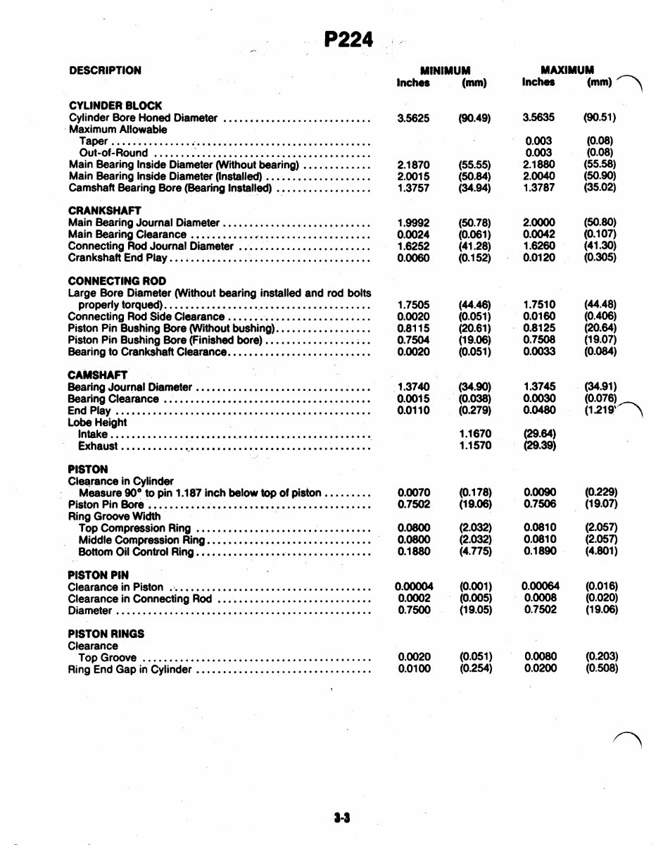
P224
DESCRIPTION
CYLINDER BLOCK
Cylinder Bore Honed Diameter ............................
Maximum Allowable
Taper ............... .................................
Out-of-Round ..........................................
Main Bearing Inside Diameter (Without bearing) .............
Main Bearing Inside Diameter (Installed) ....................
Camshaft Bearing Bore (Bearing Installed) ..................
CRANKSHAFT
Main Bearing Journal Diameter ............................
Main Bearing Clearance ..................................
Connecting Rod Journal Diameter .........................
Crankshaft End Play ......................................
CONNECTING ROD
Large Bore Diameter (Without bearing installed and rod bolts
properly torqued) ........................................
Connecting Rod Side Clearance ...........................
Piston Pin Bushing Bore (Without bushing) ..................
Piston Pin Bushing Bore (Finished bore) ....................
Bearing to Crankshaft Clearance ...........................
CAMSHAFT
Bearing Journal Diameter .................................
Bearing Clearance .......................................
End Play ................................................
Lobe Height
Intake ..................................................
Exhaust ................................................
PISTON
Clearance in Cylinder
Measure 90° to pin 1.187 inch below top of piston .........
Piston Pin Bore ..........................................
Ring Groove Width
Top Compression Ring .................................
Middle Compression Ring ...............................
Bottom Oil Control Ring .................................
PISTON PIN
Clearance in Piston .......................................
Diameter ................................................
Clearance in Connecting Rod .............................
PISTON RINGS
Clearance
Top Groove ...........................................
Ring End Gap in Cylinder .................................
MINIMUM
Inches
3.5625
2.1 870
2.0015
1.3757
1.9992
0.0024
1.6252
0.0060
1.7505
0.0020
0.81 15
0.7504
0.0020
1.3740
0.0015
0.01 10
0.0070
0.7502
0.0800
0.0800
0.1 880
0.00004
0.0002
0.7500
0.0020
0.01 00
(mm)
(90.49)
(55.55)
(50.84
(34.94)
(50.78)
(0.061)
(41.28)
(0.1 52)
(44.46)
(0.051 )
(20.61)
(1 9.06)
(0.051)
(34.90)
(0.038)
(0.279)
1 . 1670
1.1 570
(0.1 78)
(1 9.06)
(2.032)
(2.032)
(4.775)
(0.001)
(0.005)
(1 9.05)
(0.051)
(0.254)
Inches
3.5635
0.003
0.003
2.1 880
2.0040
1.3787
2.0000
0.0042
1.6260
0.01 20
1.751 0
0.01 60
0.81 25
0.7508
0.0033
1.3745
0.0030
0.0480
(29.64)
(29.39)
0.0090
0.7506
0.081 0
0.081 0
0.1 890
0.00064
0.0008
0.7502
0.0080
0.0200
(90.51)
(0.08)
(0.08)
(55.58)
(50.90)
(35.02)
(50.80)
(0.1 07)
(41 . 30)
(0.305)
(44.48)
(0.406)
(20.64)
(1 9.07)
(0.084)
(34.91)
(0.076)
(1
(0.229)
(1 9.07)
(2.057)
(2.057)
(4.801)
(0.01 6)
(0.020)
(1 9.06)
(0.203)
(0.508)
You're Reading a Preview
What's Included?
 Lifetime Access
Fast Download Speeds
Online & Offline Access
Access PDF Contents & Bookmarks
Full Search Facility
Print one or all pages of your manual
$41.99
ONAN TORO POWER PLUS P216 18 20 24 EngineS Workshop Manual
Viewed 87 Times Today

What's Included?
Lifetime Access
Fast Download Speeds
Online & Offline Access
Access PDF Contents & Bookmarks
Full Search Facility
Print one or all pages of your manual
$41.99

Secure transaction
What's Included?
Lifetime Access
Fast Download Speeds
Online & Offline Access
Access PDF Contents & Bookmarks
Full Search Facility
Print one or all pages of your manual
Description
Get access to the comprehensive workshop service repair manual for the ONAN TORO POWER PLUS P216, 18, 20, 24 engines. This manual is an invaluable resource for professional mechanics and DIY enthusiasts alike. It provides detailed technical information and step-by-step procedures for engine maintenance, repair, and troubleshooting.
Whether you're looking to perform routine maintenance or tackle more complex engine repairs, this manual equips you with the knowledge and instructions needed to get the job done effectively. With clear and concise explanations, it covers a wide range of engine components and systems, making it an essential reference for anyone working with these engines.


