


Service Manual
For use with GP40N/NF-GP55N/NF Chassis Service Manual. 99739-31100
TB45 Gasoline Engine
111219-up


GROUP INDEX Items
EG ENGINE GENERAL
PRECAUTIONS FOR SAFETY AND QUALITY, HOW TO USE THIS
MANUAL, TROUBLE DIAGNOSIS, ECM GENERAL SERVICE
INFORMATION, PRECAUTIONS, PREPARATION, SERVICE DATA
ET ENGINE TUNE-UP
VALVE CLEARANCE, ENGINE DRIVE BELT, ENGINE OIL,
COMPRESSION PRESSURE, SPARK PLUG
EM ENGINE MECHANICAL
INTAKE MANIFOLD, EXHAUST MANIFOLD, OIL PAN AND OIL
STRAINER, ROCKER COVER, ROCKER ARM AND ROCKER
SHAFT ASSEMBLY, CYLINDER HEAD, TIMING CHAIN, CYLINDER
BLOCK
LU ENGINE LUBRICATION
OIL PUMP
CO ENGINE COOLING
SYSTEM
ENGINE COOLANT, WATER PUMP, THERMOSTAT
EC ENGINE CONTROL
PRECAUTIONS, ENGINE CONTROL SYSTEM, TROUBLE
DIAGNOSIS, BASIC INSPECTION, BATTERY AND GROUND
SYSTEM, CRANKSHAFT POSITION SENSOR 1º (POS),
CRANKSHAFT POSITION SENSOR 120º (REF), MASS AIR FLOW
SENSOR SYSTEM, ENGINE COOLANT TEMPERATURE SENSOR
SYSTEM, HEATED OXYGEN SENSOR SYSTEM, THROTTLE
POSITION SENSOR SYSTEM, ACCELERATOR PEDAL POSITION
SENSOR SYSTEM, NEUTRAL SWITCH SYSTEM, INTAKE AIR
TEMPERATURE SENSOR SYSTEM, STOP LAMP SWITCH
SYSTEM, ELECTRICAL LOAD SWITCH SYSTEM, IGNITION
SYSTEM, FUEL INJECTOR SYSTEM (GASOLINE) , FUEL PUMP
SYSTEM, THROTTLE CONTROL MOTOR SYSTEM, HEATED
OXYGEN SENSOR HEATER SYSTEM, LPG INJECTOR SYSTEM,
LPG ASSISTANCE INJECTOR SYSTEM, LPG FUEL PRESSURE
SENSOR SYSTEM, LPG INTERCEPTION VALVE SYSTEM, FUEL
CONTROL CHANGING SWITCH SYSTEM, PCV GAS
RESTORATION DEVICE, FUEL CUT FUNCTION, ECM
COMPONENTS, SERVICE DATA AND SPECIFICATIONS (SDS)
FL ENGINE FUEL SYS-
TEM
FUEL SYSTEM, FUEL INJECTOR (GASOLINE AND COMBINED
USE), LPG PARTS
EL ENGINE ELECTRICAL
SYSTEM
STARTING SYSTEM, CHARGING SYSTEM,
HIGH-TENSION CABLE
GROUP INDEX
EM
LU
CO
EC
FL
EL
EG
ET

SECTION EG
ENGINE GENERAL
CONTENTS
PRECAUTIONS FOR SAFETY AND
QUALITY ............................................................. EG-2
Description ..................................................... EG-2
Safe Operation ............................................... EG-2
Correct Operation ........................................... EG-3
Precautions for Radio Equipment
Installation ...................................................... EG-3
HOW TO USE THIS MANUAL ............................ EG-4
Description ..................................................... EG-4
Definition of Terms ......................................... EG-4
Definition of Units ........................................... EG-4
Description ..................................................... EG-5
Component Parts Location ............................. EG-5
TROUBLE DIAGNOSIS ...................................... EG-7
ECM Trouble Diagnosis ................................. EG-7
ECM Abbreviations List ................................ EG-10
ECM GENERAL SERVICE INFORMATION ..... EG-11
Connector Terminal Inspection .................... EG-11
Inspection for Electrical System ................... EG-12
Control Unit and Electronic Component ....... EG-13
PRECAUTIONS ................................................ EG-14
Precautions in Draining Engine Coolant ....... EG-14
Precautions for Disconnecting Fuel Piping ... EG-14
Precautions for Removing and
Disassembling .............................................. EG-14
Precautions for Inspection, Correction, and
Replacement ................................................ EG-14
Precautions for Assembly and Installation ... EG-14
Caution for Use of Power Tools ................... EG-15
Precautions for Liquid Gasket Application .... EG-15
Parts Requiring Angle Tightening ................. EG-16
PREPARATION ................................................ EG-17
Service Parts ................................................ EG-17
SERVICE DATA ................................................ EG-18
Periodical Inspection .................................... EG-18
Standard, Repair Limit .................................. EG-20
Tightening Torque ........................................ EG-21
EG-2
PRECAUTIONS FOR SAFETY AND QUALITY
PRECAUTIONS FOR SAFETY AND QUALITY
Description
• The following precautions must be carefully observed for safe
and appropriate service work.
• Only the qualified and designated personnel must perform
inspections, repairs and adjustments.
• Always keep the workplace clean, and store the tools neatly in
the specified places.
Safe Operation
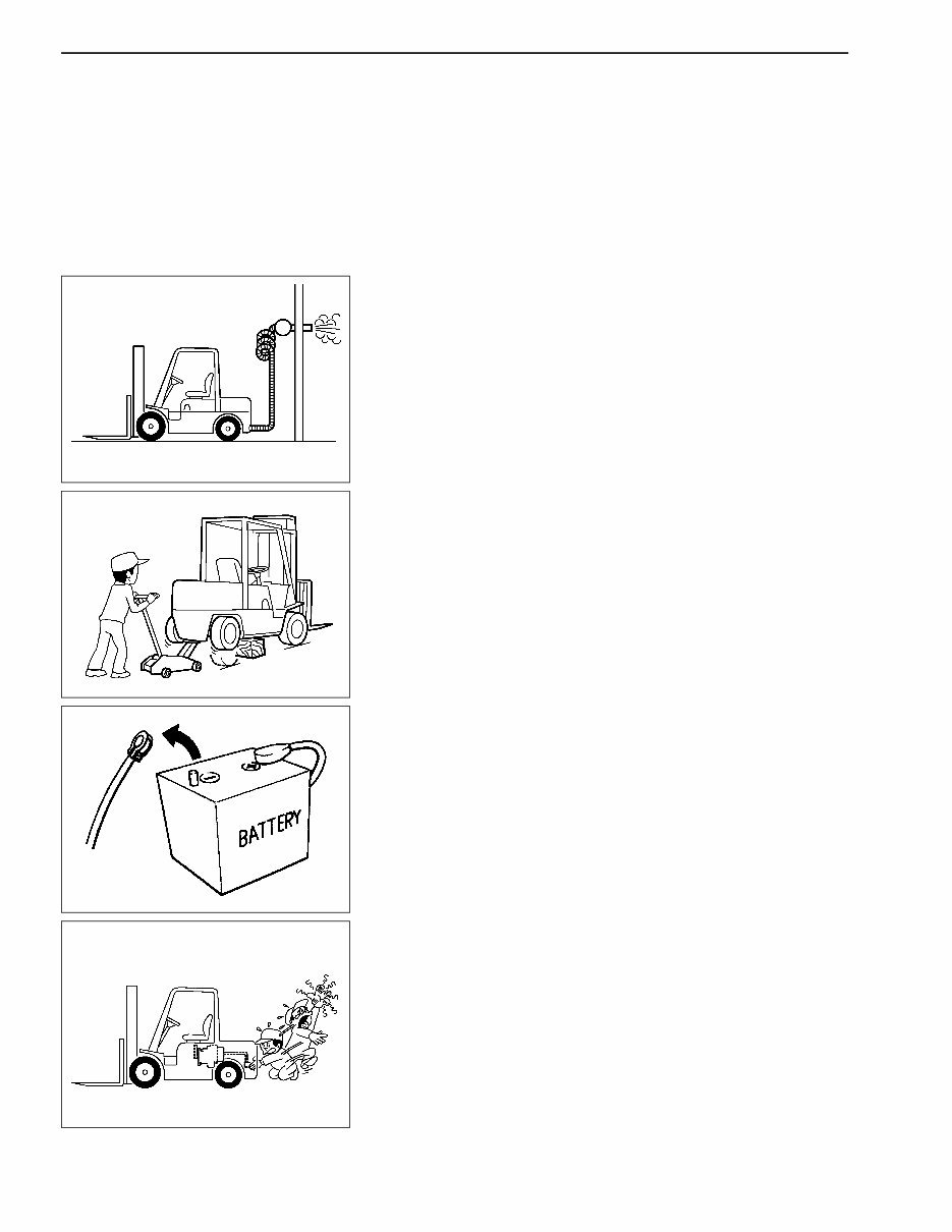
• Do not run an engine inside the workshop without proper
ventilation (ex. no ventilation ducts).
• Keep the workshop well ventilated and free of any flammable
materials. Special care should be taken when flammable or
poisonous materials such as gasoline are handled.
• Discard waste oil after oil changes or parts treatment in
accordance with local laws and regulations.
• Be careful of burns and injury when working on high-
temperature parts, rotating parts, or sliding portions.
• Ensure that adequate ventilation is provided for discharging any
hazardous emissions when working in a pit or enclosed area.
• Do not work underneath a vehicle supported only by a jack.
Always use safety stands at the prescribed points to support the
vehicle.
• Support it at the prescribed points and lock it in position with
safety devices before lifting the vehicle.
• Be careful that the vehicle body does not become off balance
and fall when removing a heavy component such as the engine.
• Do not smoke during service work.
• Do not wear any rings and necklaces when working. These
objects may cause electric short.
• Before starting repair work that requires no battery power,
always turn OFF the ignition switch, and disconnect the
negative battery cable.
• Do not disconnect battery cable at negative terminal while
engine is running.
• Do not touch any metal portions immediately after the engine is
stopped. Otherwise the heated metals may cause burns. Do not
attempt to remove any cooling system parts such as the radiator
cap while the engine is hot.
• To perform repair work safely and efficiently, always use
appropriate tools wherever required.
• Do not continue filling the fuel if automatic valve of refilling
nozzle is closed when fuel tank is filled. The fuel can overflow
and splash, and it can cause a fire.
EGM0043
EGM0044
EGM0045
EGM0046

EG-3
PRECAUTIONS FOR SAFETY AND QUALITY
Correct Operation
• Make sure that you understand the symptoms before starting
trouble diagnosis.
• Check correct installation status prior to removal or
disassembly. Make sure that they do not interfere with the
function of the parts they are applied to if matching marks are
required.
• Once they are removed, always replace parts indicated as “do
not reuse” with new ones. This includes: oil seals, gaskets,
packings, O-rings, lock washers, cotter pins, and self-locking
nuts.
• Replace inner and outer races of tapered or needle roller
bearings as a set.
• Arrange disassembled parts in order and prevent them from
being mixed-up.
• Clean or flush disassembled parts prior to inspection or
assembly.
• Use Genuine NISSAN parts for replacement.
• Use authorized grease and sealer.
• Release the pressure before disconnecting pressurized piping
or hoses.
• Be sure to check for leakage after repairing fuel, oil, coolant,
exhaust, or vacuum systems.
Precautions for Radio Equipment Installation
Check the following when installing a commercial/ham radio or
mobile phone. If mounting position is not chosen carefully, the unit
may interfere with the electronic control system.
• Separate the antenna as far from the ECM as possible.
• Route an antenna feeder line at least 20 cm (7.87 in) apart from
the control unit harness.
• Adjust an antenna and feeder line to eliminate radio wave
interference.

EG-4
HOW TO USE THIS MANUAL
HOW TO USE THIS MANUAL
Description
This manual explains how to perform “removal, installation,
disassembly, assembly, inspection and adjustment” and “diagnosis”.
Definition of Terms
WARNING : Instructions and precautions that may lead to fatal
hazards and/or serious injuries if not observed
properly.
CAUTION : Instructions and precautions that require special
attention and may lead to problems and/or accidents
as well as damages to the vehicle and/or
components.
NOTE : Supplementary information to facilitate the service
work.
Standard : Indicates tolerances for inspection and adjustment.
Repair limit : Indicates maximum or minimum values allowed for
inspection and adjustment.
Definition of Units
The units and numerical values in this Standard are SI units, and
those given in ( ) in this Standard are based on the conventional unit
system and are appended for informative reference.
Example: : 59 - 78 N•m (6.0 - 8.0 kg-m, 43 - 58 ft-lb)
SI (Metric system, yard-pound system)
* The conventional unit can be used for SI.
MAIN UNIT CHANGES
Measure SI Conventional unit Conversion factor to SI
Acceleration
m/s
2
G 9.80665
Torque, moment N•m kg-m 9.80665
Force N kg 9.80665
Pressure kPa
kg/cm
2
98.07
kPa mmHg 0.133322
Power efficiency kW PS 0.735499
W kcal/h 1.16279
Volume
cm
3
cc 1
Spring constant N/mm kg/mm 9.80665
Fuel consumption g/kW•h * g/PS•h 1.3596
EG-5
HOW TO USE THIS MANUAL
Description
CAUTION : At the beginning of each section, the precautions
exclusive to the section are described.
Preparation: At the beginning of each section and during the trouble
diagnosis items, the tools, gauges, and other tools to
be prepared before operation are described. Some
commercial service tools, assumed to be available in
any workshop, are omitted.
Description : To perform correct operations, operational procedures,
notes, tools, and other service information are
described.
CAUTION : Descriptions of visual inspections and cleaning of
removed parts are generally omitted. Please
remember that actual operations require these
processes.
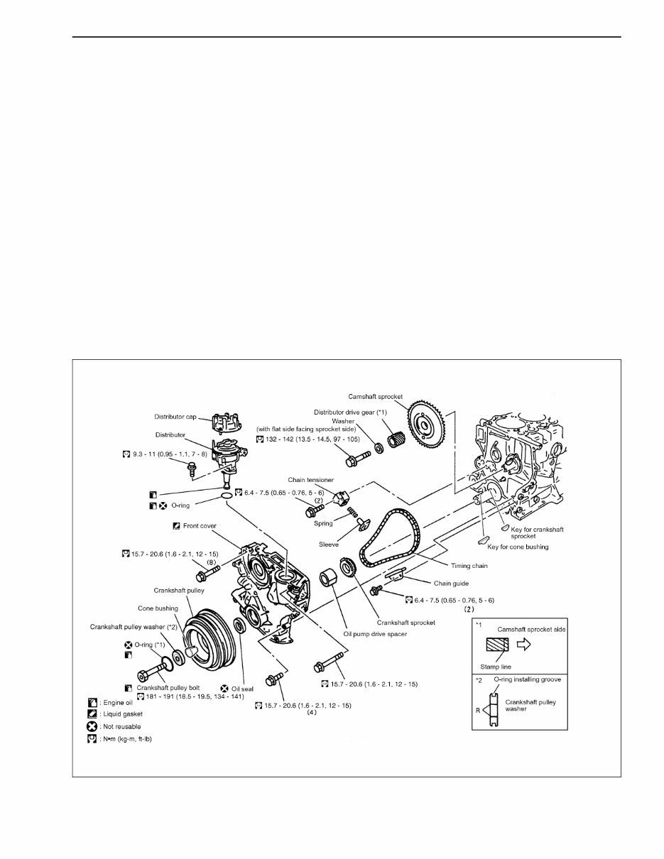
Component Parts Location
The “Component Parts Location” diagram (refer to the figure)
includes information for removal, installation, disassembly, and
assembly (tightening torque, grease points, non-reusable parts) as
well as other information important for repair work.
EGM0097
EG-6
HOW TO USE THIS MANUAL
Component Parts Location (Cont’d)
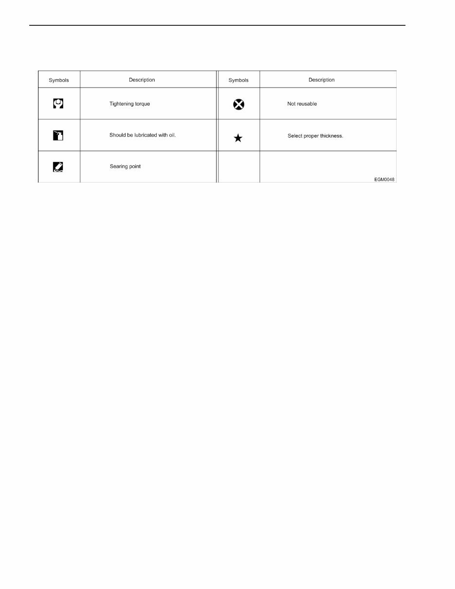
COMPONENT SYMBOLS

EG-7
TROUBLE DIAGNOSIS
TROUBLE DIAGNOSIS
ECM Trouble Diagnosis
CAUTION:
• The following trouble diagnosis procedures are designed
to identify the trouble causes efficiently. When performing
diagnoses, carefully observe the following instructions.
• Before starting a trouble diagnosis, carefully read and
understand the contents in “Basic Inspection”, “Diagnosis
Chart by Symptom” and “Trouble Diagnosis Flowchart”.
• After the repair work, always verify that the trouble is
eliminated.
• For the locations of the parts and harness connectors, refer
to “Component Parts Location” in the relevant section.
• To perform a simple inspection, utilize the circuit diagrams.
To inspect the circuit for continuity in details including the
sub-harnesses, identify the relevant connectors and
harness layouts referring to the “Wiring Diagrams”.
• Before inspecting a circuit for continuity, always turn the
ignition switch to OFF.
• Before measuring voltage at a connector, always measure
the battery voltage.
• After finishing diagnoses or inspections, always ensure
that all removed harness connectors are reconnected
correctly.
You're Reading a Preview
What's Included?
Fast Download Speeds
Online & Offline Access
Access PDF Contents & Bookmarks
Full Search Facility
Print one or all pages of your manual
$41.99
TB45 Gasoline Engine With GP40N NF-FP5 service repair manual
Viewed 73 Times Today

What's Included?
Fast Download Speeds
Online & Offline Access
Access PDF Contents & Bookmarks
Full Search Facility
Print one or all pages of your manual
$41.99

Secure transaction
What's Included?
Fast Download Speeds
Online & Offline Access
Access PDF Contents & Bookmarks
Full Search Facility
Print one or all pages of your manual
Description
Get the comprehensive service repair manual for the TB45 gasoline engine with GP40N, NF-FP55N, and NF models. This manual is an essential resource for professional mechanics and DIY enthusiasts alike. It provides detailed technical information and instructions for maintenance, repair, and troubleshooting. Whether you're working on the engine or the GP40N, NF-FP55N, or NF models, this manual is a valuable tool for ensuring optimal performance and reliability.


