

New Holland Engines Parts Catalog Service Manual
What's Included?
Fast Download Speeds
Online & Offline Access
Access PDF Contents & Bookmarks
Full Search Facility
Print one or all pages of your manual
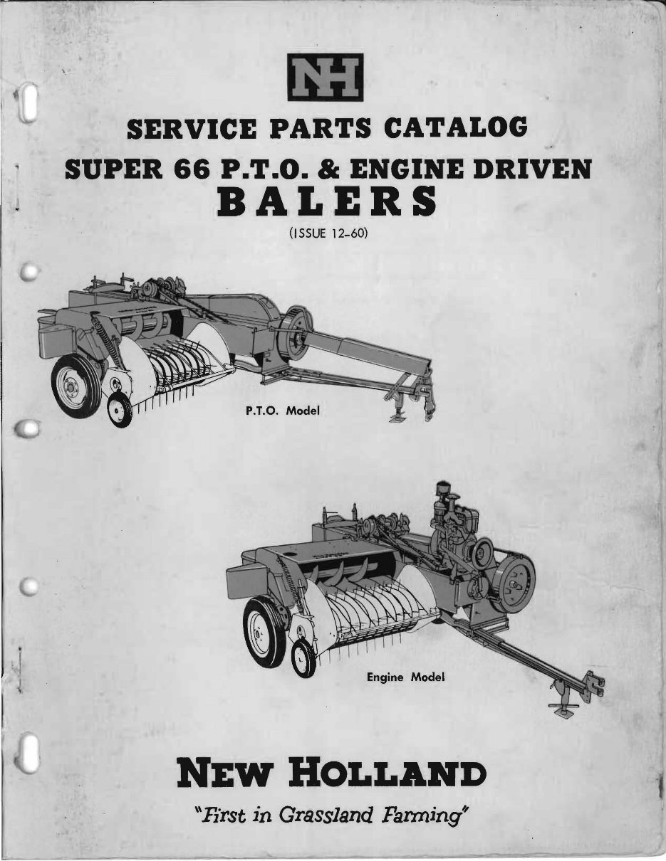
SERVICE PARTS CATALOG
SUPER 66 P.T.O. " ENGINE DRIVEN
BALERS
(I SSUE 12-60)
P.T.O. Model
Engine Model
\'First in Grassland Farming"
ORDERING PARTS
When ordering service parts follow the instructions listed below. By so doing,
you will be assured of receiving the correct part in the shortest possible time.
1. Give the Baler model and serial number.
2. Write the complete part number as well as the description of the
part.
3. Whenever the terms "left and right, or Land R," are used herein,
it should be understood to mean from a position facing in direction
of Baler travel.
4. Give detailed shipping instructions, that is: Railroad station, county;
whether shipment is to go by parcel post, air express, express,
freight or truck.
The New Holland Machine Company is continually striving to improve
its products.
We must, therefore, reserve the right to make imprpvements, or changes,
when it becomes practical and possible to do so, without incurring any obliga-
tion to make changes or additions, to the equipment sold previously .
I
CONTENTS
I 1 P.T.O. AND ENGINE DRIVEN MODEL SUPER 66 BALERS
I
Assembly Page
Tongue .............................................................................................................. 4
Flywheel, Gearbox and Crank .................... ..... ... .................... .......................... 5
Gearbox .......................................................................................................... 6, 7
Connecting Rod, Feeder and Knotter Drive Assemblies ...... .......... ..... ........... 8, 9
I - Feeder Plunger ....................................................................... ........... .............. 10
Plunger Assemblies ............................................................................ 12, 13, 14
Twine Finger and Lever Assemblies ................................................................ 15
Knotter Assembly ........................................................................ 16, 17, 18, 19
Needle Yoke, Rod and Brake Arm Assemblies .......................................... 20, 21
Metering Wheel Assembly.................................................. ...... ........................ 22
Bale Tension Assembly .................................................................................... 23
Pick-up Assembly... ... ............ .............. ......... ...... ....................... ........ 24, 25, 26
Windguard Assembly ........................................................ ......... ..................... 27
Feeder Shell Assembly .......................................................................... 28, 29, 30
Wadboard Assembly......... ... ............... .............................. ........................ ....... 31
Twine Box Assembly ..........................:................. ...... ........................... ........... 33
•
Axle Assembly and Brace ............... ......... ..................... ..... .................. ....... 34, 35
.•~
Main Frame, Crank Guard, and Bale Chute Assemblies
Auger Assembly ............................... '" .................................................... ... ..... 32 d
.................................... 35
i
1
ENGINE DRIVEN MODEL SUPER 66 BALERS
Gasoline Line, Tank and Belt Tightener Assemblies .......................................... 36
Engine Mount and Main Drive Assemblies ................................................ 37, 38
P.T.O. DRIVEN MODEL SUPER 66 BALERS
() P.T.O. Assembly, Front .................................................................................... 40
Bearing and Tube Assembly ...................... ...................................................... 41
P.T.O. Assembly, Rear ...................................................................................... 42
Clutch ................................................................................................................ 43
P.T.O. Guards .................................................................................................. 44
P.T.O. AND' ENGINE DRIVEN MODEL SUPER 66 BALER ATTACHMENTS
Wagon Hitch and Bale Chute .......................................................................... 45
Jack Assembly.......... .......... ........................ ........ ....................... ...... ........ ......... 46
Overall Baler Covers ........................................................................................ 46
Hydraulic Bale Tension .............................................................. 47, 48, 49, 50
Numerical Index .......................................................................... 51, 52, 53, 54
•
HARDWARE KEY
\
'1
Throughout this manual you find common hardware, not illustrated, but
listed in the description column. The service part immediately preceding a hard-
l
ware listing is the part using these particular items for mounting or lubricating \
purposes. This hardware is not included with the service part or assembly, when
1
ordered as a replacement.
I
3
-- --~.-......... ....
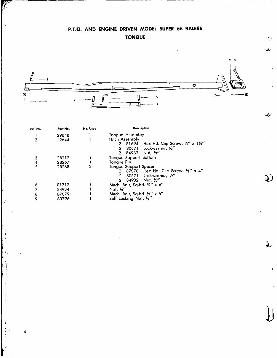
P.T.O. AND ENGINE DRIVEN MODEL SUPER 66 BALERS
TONGUE
~
7=
0
IfiI
La
~
®
l__ ~__ s--()
~
0----
5
9
l-
-
-,
..J..;
Ref. No. Part No. No.Used Description
1 29848
Tongue Assembly
2 12644
Hitch Assembly
2 81694 Hex Hd. Cap Screw, %11 x 1:IA"
2 80671 lockwasher, Yl'
2 84932 Nut, V2"
3 28217 1 Tongue Support Bottom
4 28267 1 Tongue Pin
5 28268 2 Tongue Support Spacer
2 87078 Hex Hd. Cap Screw, Yi' x 4"
2 80671 lockwasher, V2"
~.
2 84932 Nut, %"
6 81712 Mach. Bolt, Sq-hd. %" x 6"
7 84934 Nut, %/1
8 87079 Mach. Bolt, Sq-hd. %" x 6"
:
9 80796 Self locking Nut, Y2
11
.)
4
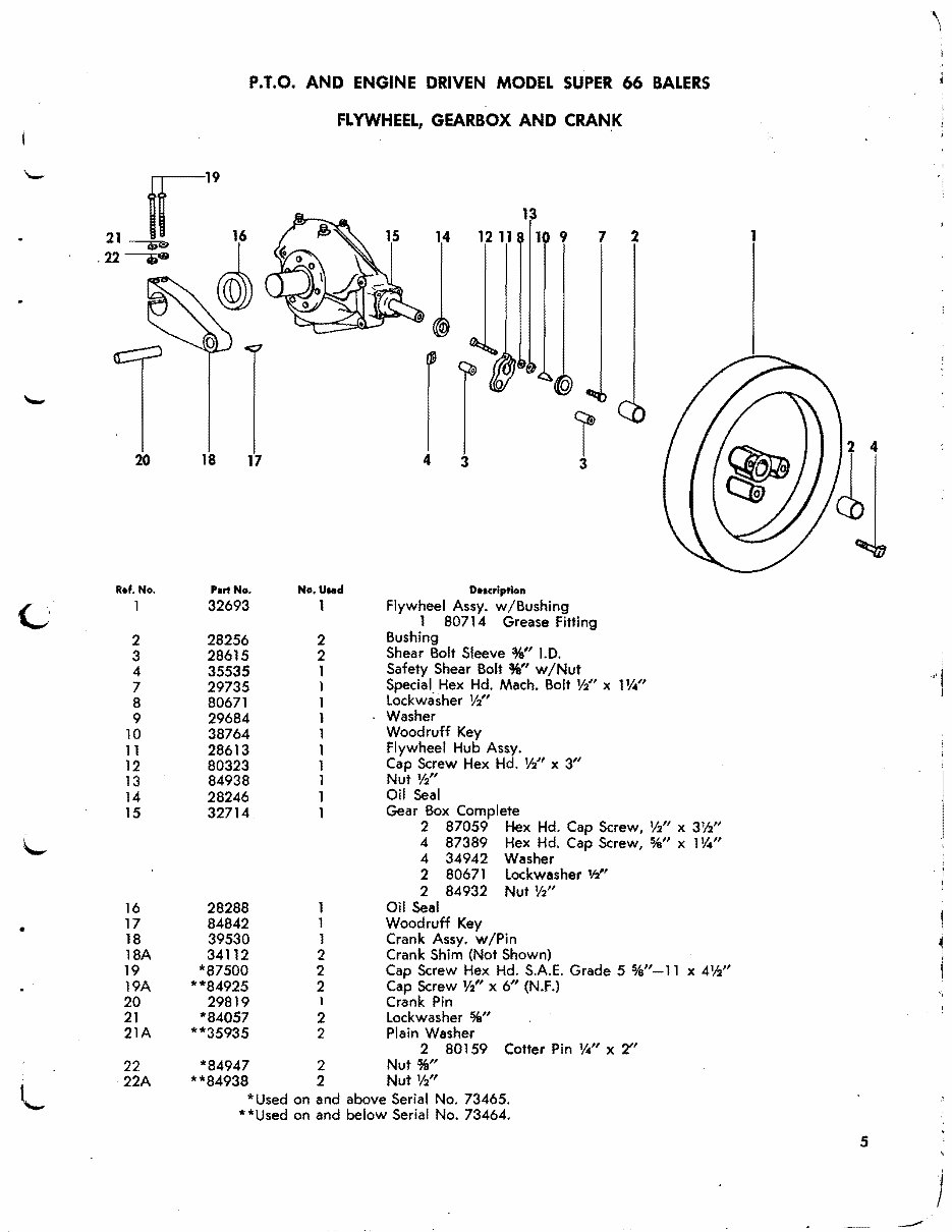
P.T.O. AND ENGINE DRIVEN MODEL SUPER 66 BALERS
FLYWHEEL, GEARBOX AND CRANK
13
14 12 11 1 9 1 2 1
1
r
@
I
20 18 17 4
3
3
CI
R.f. No. Part No. No.U..d D••crlptlon
1 32693 1 Flywheel Assy. w/Bushing
1 80714 Grease Fitting
2 28256 2
Bushing
3 28615 2
Shear Bolt Sleeve %" J.D.
4 35535 1
Safety Shear Bolt %" w/Nut
7 29735 1
Special Hex Hd. Mach. Bolt %" x 1114"
"I
8 80671 1
Lockwasher Y:l'
9 29684 1
Washer
10 38764 1
Woodruff Key
11 28613 1
Flywheel Hub Assy.
12 80323 1
Cap Screw Hex Hd. Yl' x 3"
13 84938 1 Nut Yl'
14 28246 1
Oil Seal
15 32714 1
Gear Box Complete
2 87059 Hex Hd. Cap Screw, Y2" x 3%"
4 87389 Hex Hd. Cap Screw, %" x 1114"
4 34942 Washer
2 80671 Lockwasher 112"
i
i
2 84932 Nut %"
16 28288 1 Oil Seal
17 84842 1 Woodruff Key
•
18 39530 1 Crank Assy. w/Pin
18A 34112 2 Crank Shim (Not Shown)
19 *87500 2 Cap Screw Hex Hd. S.A.E. Grade 5 %"-11 x 4%"
19A **84925 2 Cap Screw Yl' x 6" (N.F.)
20 29819 1 Crank Pin
21 *84057 2 Lockwasher %"
21A **35935 2 Plain Washer
2 80159 Cotter Pin 114" x 2"
22 *84947 2 Nut %"
22A **84938 2 Nut %"
*Used on and above Serial No. 73465.
l..
* *Used on and below Serial No. 73464.
5
j
---"
" ..... ,...--- ,__ ,,:7 .. s~. 0:""" i "'Nit..:.. , .. .m~____...~....",...._~_ -~ __:;-.
- .. ~
0-
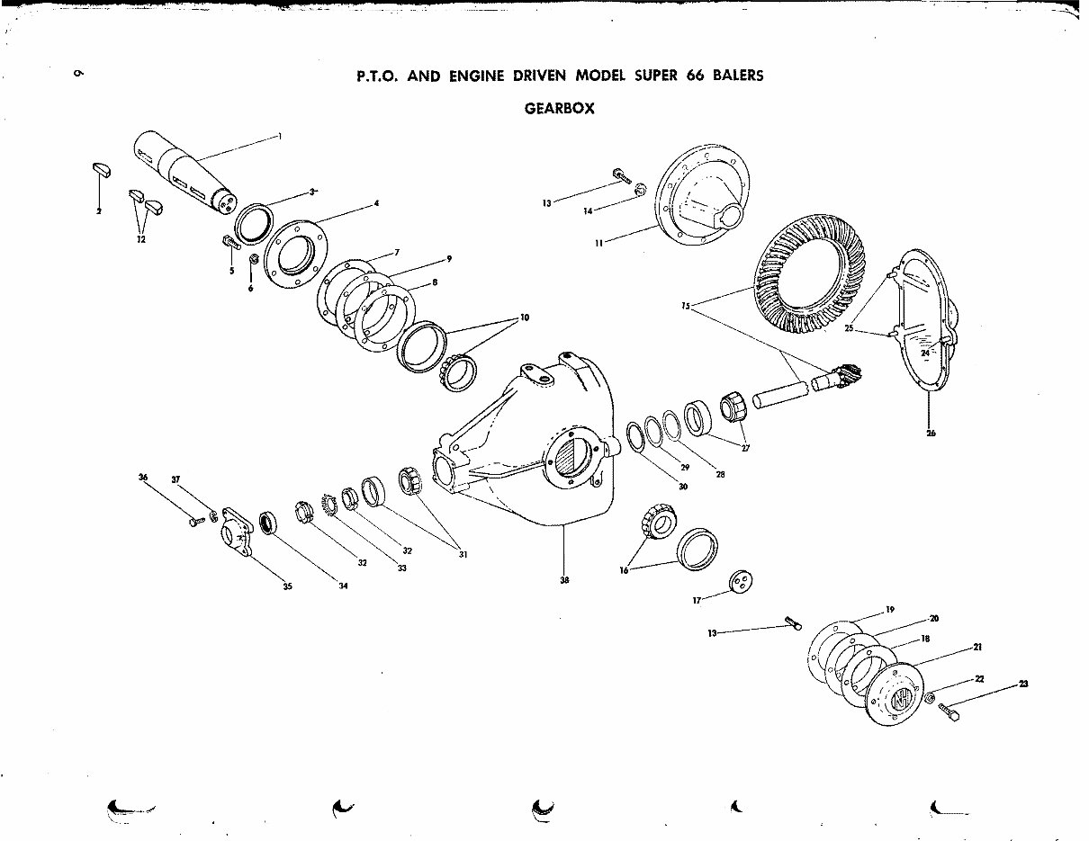
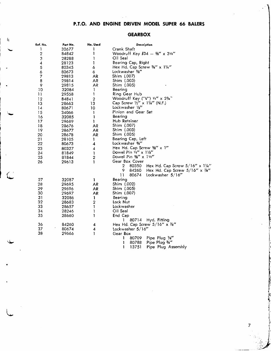
P.T.O. AND ENGINE DRIVEN MODEL SUPER 66 BALERS
GEARBOX
~~
30 28
,to
~
26
17~
20
22 23
I~
.~ ... ~
~
~
~
~.
21
5
10
15
20
25
30
35
P.T.O. AND ENGINE DRIVEN MODEL SUPER 66 BALERS
1\
Ref. No.
1
'-
2
3
4
6
7
8
9
11
12
13
14
"-'
16
17
18
19
21
22
23
24
26
1"
~
27
28
29
31
32
33
34
36
37
38
~
Part No.
32677
84842
28288
28123
80345
80673
29813
29814
29815
32084
29558
84841
28663
80671
34066
32085
29689
28676
28677
28678
28105
80673
80327
81849
81844
29613
32087
29695
29696
29697
32086
28683
28657
28246
28660
84260
80674
29666
No.Used
1
1
1
1
6
6
AR
AR
AR
1
1
2
13
10
1
1
1
AR
AR
AR
1
4
4
1
2
1
1
AR
AR
AR
1
2
1
1
1
4
4
1
GEARBOX
Descriplion
Crank Shaft
Woodruff Key #34 - %" x 31f2"
Oil Seal
Bearing Cap, Right
Hex Hd. Cap Screw %" x 1 %"
Lockwasher %n
Shim (.007)
Shim (.003)
Shim (.005)
Bearing
Ring Gear Hub
Woodruff Key ("V") 112" x 2~4"
Cap Screw 1/2" x 1%" (N.F.)
Lockwasher Yi'
Pinion and Gear Set
Bearing
Hub Retainer
Shim (.007)
Shim (.003)
Shim (.005)
Bearing Cap, Left
Lockwasher %"
Hex Hd. Cap Screw %" x 1"
Dowel Pin 112" x 1Yi'
Dowel Pin %" x 1V2"
Gear Box Cover
2 80350 Hex Hd. Cap Screw 5/16" x 1%/1
9 84260 Hex Hd. Cap Screw 5/16" x %"
11 80674 Lockwasher 5/16"
Bearing
Shim (.002)
Shim (.005)
Shim (.007)
Bearing
Lock Nut
Lockwasher
Oil Seal
End Cap
1 80714 Hyd. Fitting
Hex Hd. Cap Screw 5/16" X 1'8"
Lockwasher 5/16"
Gear Box
1 80709 Pipe Plug Va"
1 80788 Pipe Plug %"
1 13751 Pipe Plug Assembly
7
--
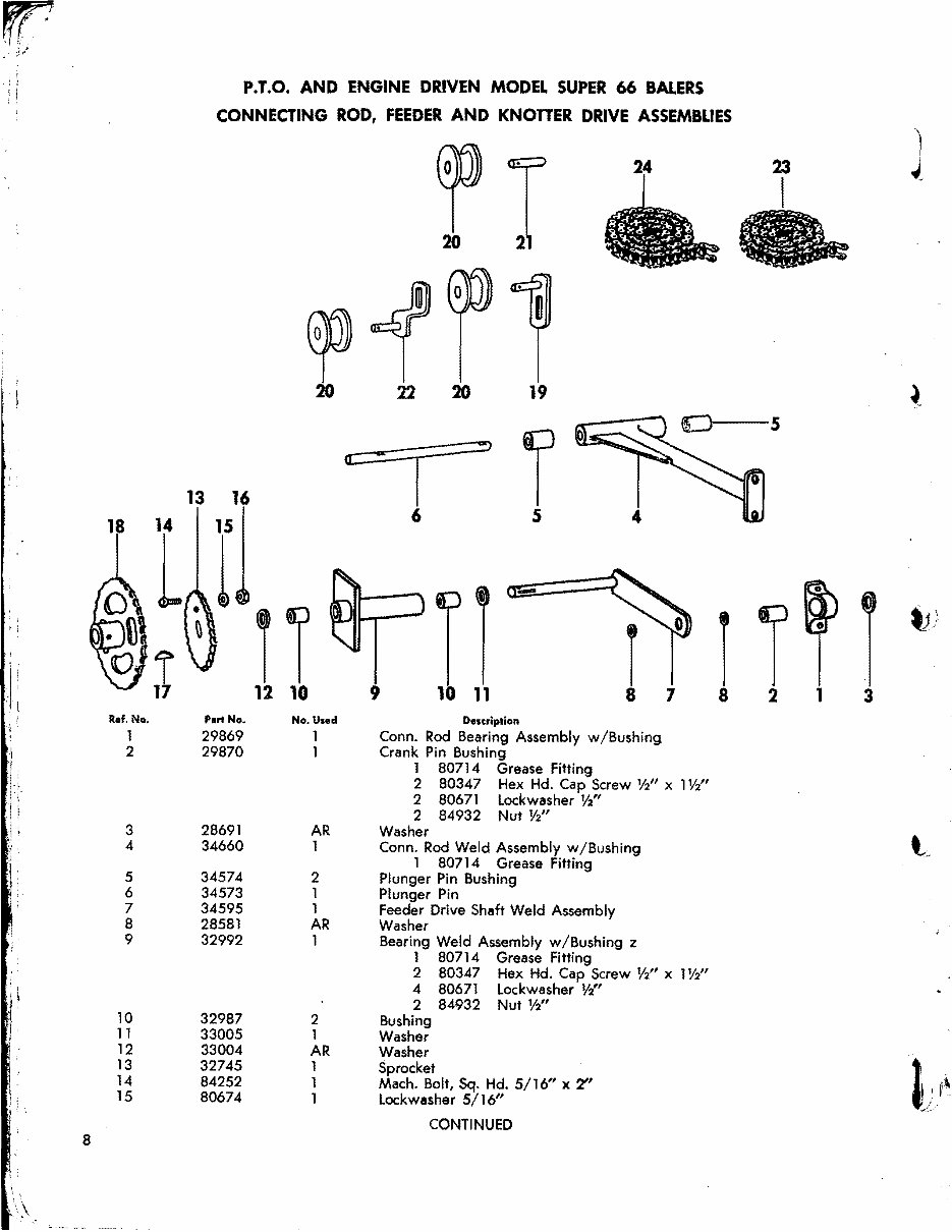
P.T.O. AND ENGINE DRIVEN MODEL SUPER 66 BALERS
CONNECTING ROD, FEEDER AND KNOTTER DRIVE ASSEMBLIES
~T
23
20 21
0p
, t
20 22 20 19
~
5
I
:!!)
r
13 16
18 14 15
L 1
6 5
,
~ i
" l
• I
Ref, No. P.rt No •
1 29869
I
2 29870
I.
I
:r.
1\
I ~ 3 28691
.1
4 34660 ~i
1:
5 34574
6 34573
7 34595
,
8 28581
:1
9 32992
r
1
10 32987
11 33005
12 33004
13 32745
14 84252
15 80674
tJ)
I T
r r r r
12 10 9 10 11 7 8 2 1 3
No. UHd Description
1 Conn. Rod Bearing Assembly w /Bushing
1 Crank Pin Bushing
1 80714 Grease Fitting
2 80347 Hex Hd. Cap Screw %" x 1%"
2 80671 Lockwasher V2"
2 84932 Nut %"
AR Washer
1 Conn. Rod Weld Assembly w/Bushing
~
1 80714 Grease Fitting
2 Plunger Pin Bushing
1 Plunger Pin
1
Feeder Drive Shaft Weld Assembly
AR Washer
1 Bearing Weld Assembly w /Bushing z
1 80714
2 80347
4 80671
2 84932
2
1
Bushing
Washer
AR Washer
1
Sprocket
Grease Fitting
Hex Hd. Cap Screw %" x 1%"
Lockwasher V2"
Nut V2"
1 Mach. Bolt, Sq. Hd. 5/16" x 2"
1 Lockwasher 5/16"
~ )fl
-->
CONTINUED
a
P.T.O. AND ENGINE DRIVEN MODEL SUPER 66 BALERS
: !
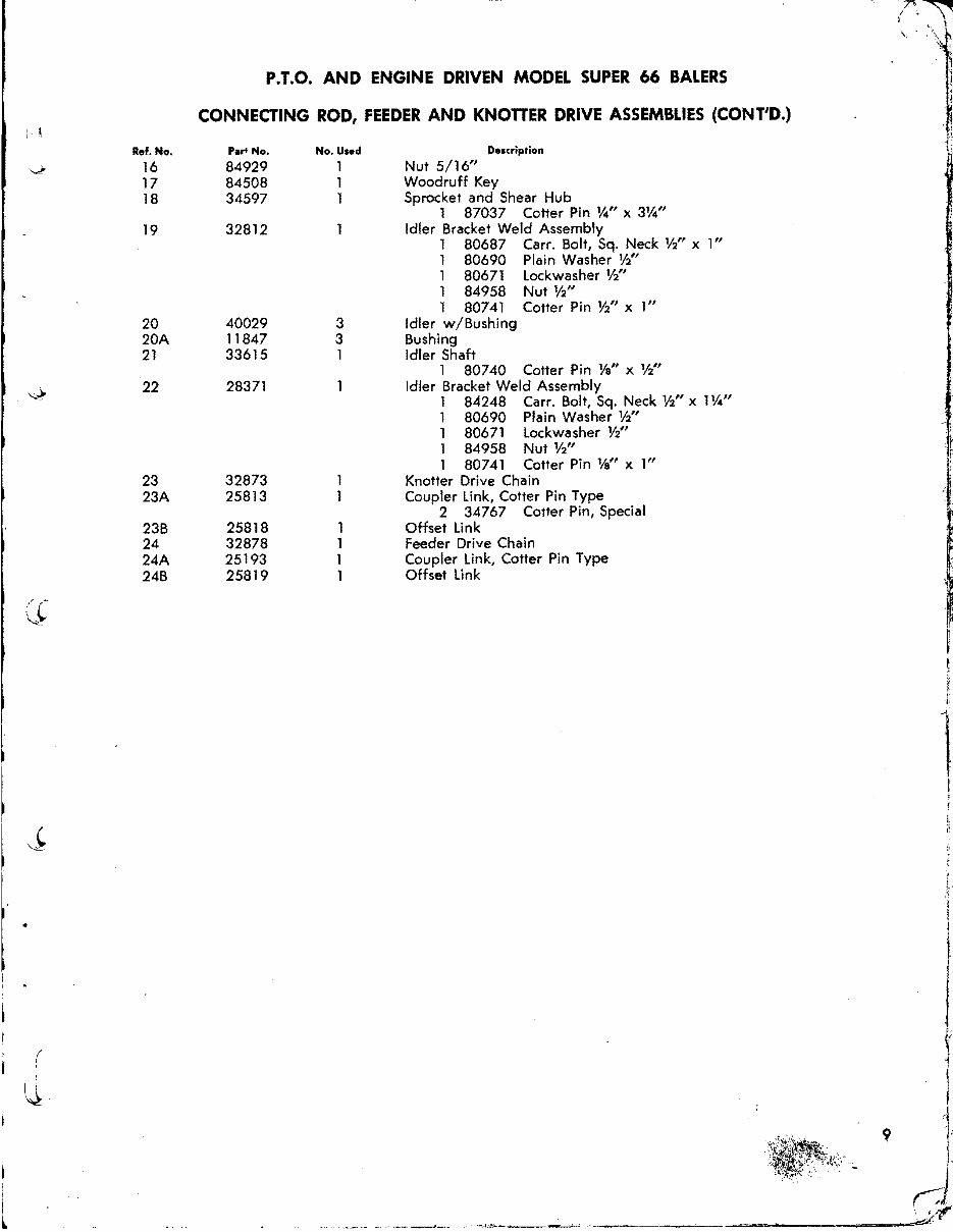
CONNECTING ROD, FEEDER AND KNOTTER DRIVE ASSEMBLIES (CONT'D.)
' I
'\
Ref. No. p... No. No. Used Description
V
16 84929 1 Nut 5/16"
17 84508 1 Woodruff Key
18 34597 1 Sprocket and Shear Hub
1 87037 Cotter Pin tA" x 3tA"
19 32812 Idler Bracket Weld Assembly
1 80687 Carr. Bolt, Sq. Neck %" xl"
1 80690 Plain Washer %"
1 80671 Lockwasher Y2"
1 84958 Nut Y2"
1 80741 Cotter Pin Y2" x 1"
20 40029 3 Idler w/Bushing
20A 11847 3 Bushing
21 33615 1 Idler Shaft
1 80740 Cotter Pin Ya" x %"
~
22 28371 Idler Bracket Weld Assembly
1 84248 Carr. Bolt, Sq. Neck %" x 1tA"
1 80690 Plain Washer %"
1 80671 Lockwasher %"
~ ;
1
1
84958
80741
Nut %"
Cotter Pin 14" x 1"
1:
,
23 32873 Knotter Drive Chain
23A 25813 Coupler Link, Cotter Pin Type
2 34767 Cotter Pin, Special
23B 25818 1 Offset Link
24 32878 1 Feeder Drive Chain
24A 25193 1 Coupler Link, Cotter Pin Type
(C
,"",
24B 25819 1 Offset Link
1
~
I
~
I
I
~
I
!
I
I
/
~
~
I.
t
., I"
~
(
I
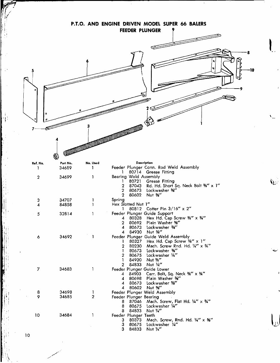
P.T.O. AND ENGINE DRIVEN MODEL SUPER 66 BALERS
FEEDER PLUNGER 9
I
5
i
::a~~~~8
~~ItDtt-l0
"-:::::~---9
,
T
~
7
4
I'
J
I
Ref. No. Part No. No. U.ed De.eripfion
34689 Feeder Plunger Conn. Rod Weld Assembly
1 80714 Grease Fitting
2 34699 Bearing Weld Assembly
,
1 80721 Grease Fitting
\tJj
r I
2 87043 Rd. Hd. Short Sq. Neck Bolt %" xl"
2 80673 Lockwasher %"
2 80602 Nut %"
3 34707 Spring
4 84858 Hex Slotted Nut 1"
1 80812 Cotter Pin 3/16" x 2"
5 32814 Feeder Plunger Guide Support
4 80328 Hex Hd. Cap Screw %" x %"
2 80692 Plain Washer %"
4 80673 Lockwasher %"
4 84930 Nut %"
6 34692 Feeder Plunger Guide Weld Assembly
1 80327 Hex Hd. Cap Screw %" xl"
2 80230 Mach. Screw Rnd. Hd. '4" x %"
1 80673 lockwasher %"
'~
2 80675 lockwasher V,{'
1 84930 Nut %"
2 84833 Nut '4"
7 34683 Feeder Plunger Guide lower
4 84903 Carr. Bolt, Sq. Neck %" x 3A"
4 80698 Plain Washer %"
4 80673 lockwasher %"
4 80602 Nut %"
8 34698 1 Feeder Plunger Weld Assembly
9 34685 2 Feeder Plunger Bearing
, I Ii !
I 8 87046 Mach. Screw, Flat Hd. '4" x 3,4"
I
8 80675 lockwasher '4"
8 84833 Nut '4"
10 34684 Feeder Plunger Teeth
~·l
3 80373 Mach. Screw, Rnd. Hd. '4" x %"
3 80675 lock washer '4" LJ
i '
3 84833 Nut '4"
i I
10
You're Reading a Preview
What's Included?
Fast Download Speeds
Online & Offline Access
Access PDF Contents & Bookmarks
Full Search Facility
Print one or all pages of your manual
$37.99
Viewed 82 Times Today


Secure transaction
What's Included?
Fast Download Speeds
Online & Offline Access
Access PDF Contents & Bookmarks
Full Search Facility
Print one or all pages of your manual
$37.99
The New Holland N/A Engines Parts Catalog is a valuable resource for obtaining detailed information about engine parts. It contains an extensive collection of detailed parts and clear, precise exploded view illustrations, making it easy to identify and locate specific parts. Whether you are a professional mechanic or a DIY enthusiast, this catalog provides the knowledge and guidance necessary for successful engine repair and maintenance.
Key features of the New Holland N/A Engines Parts Catalog:
- Comprehensive collection of detailed parts
- Clear and precise exploded view illustrations
- Easy identification and location of specific parts
- Useful for professional mechanics and DIY enthusiasts
- Provides essential knowledge and guidance for engine repair and maintenance


