Navistar Maxxforce 5 Engine Full Service & Repair Manual
What's Included?
Lifetime Access
Fast Download Speeds
Offline Viewing
Access Contents & Bookmarks
Full Search Facility
Print one or all pages of your manual
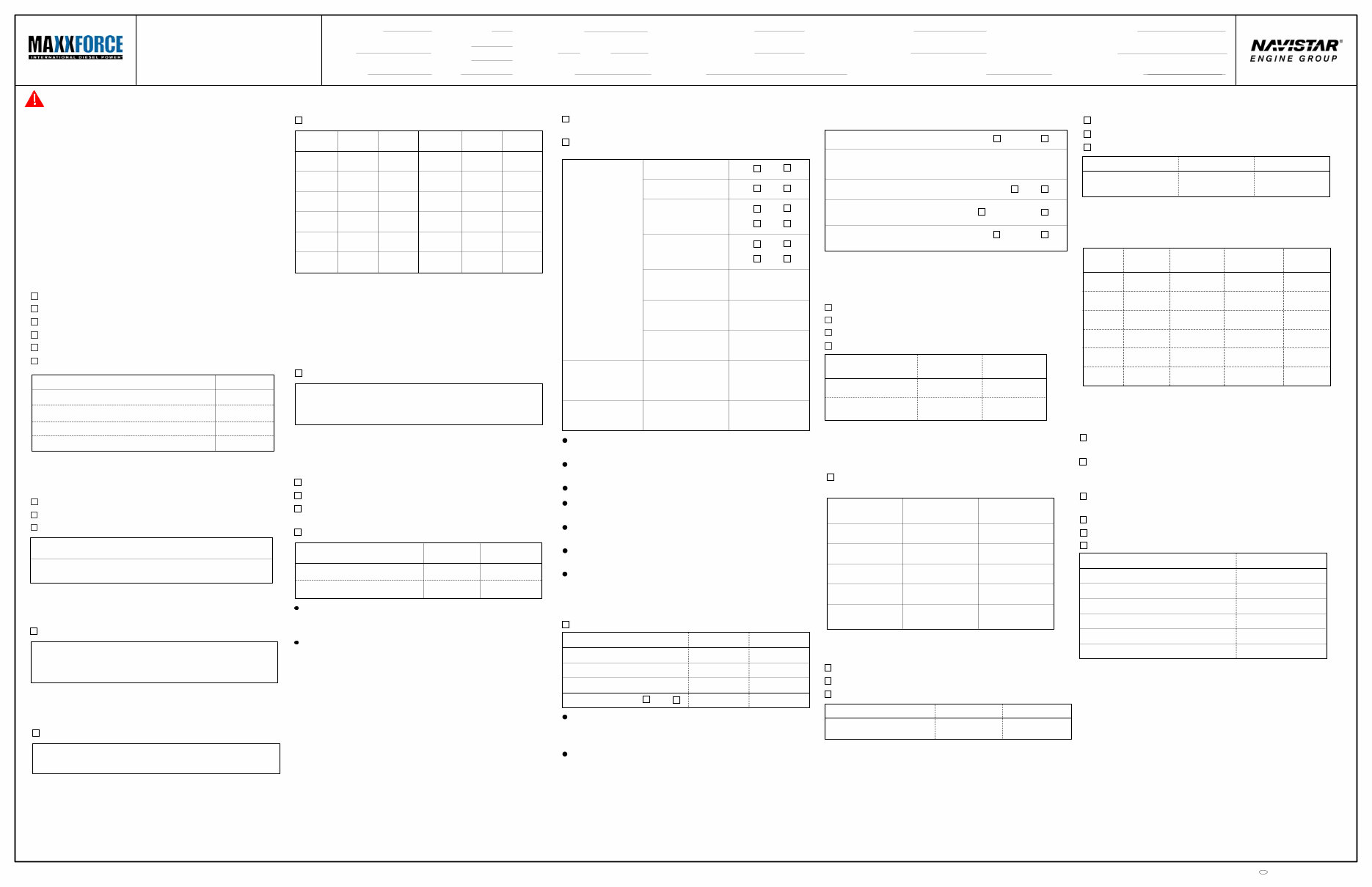
WARNING To prevent personal injury or death, read all safety instructions in the "Safety information" section of Diagnostics Manual EGES-395 before doing procedures on this form. Notes See "Performance Diagnostics" in EGES-395. Use figures and additional information to do each test or procedure. Record results on this form. Do all checks in sequence unless otherwise stated. Doing a check or test out of sequence could cause incorrect results. If a problem was found and corrected, it is not necessary to complete the rest of the form unless a performance concern remains. See EGES-395 Appendix A for Performance Specifications and Appendix B for Diagnostic Trouble Codes (DTCs). 4. KOEO Injector Test Use EST to run KOEO Injector Test. DTCs Correct problem causing DTCs before continuing. 1. Visual Inspection Engine Oil Level. Fuel Level. Engine Coolant Level. Electrical System. Exhaust System. Intake Restriction (measure at high idle). Check Oil level Fuel level Actual Coolant level Air filter restriction gauge or Gauge Bar Tool 3. KOEO Standard Test DTCs Correct problems causing DTCs before continuing. Use EST to run KOEO Standard Test 2. ECM Calibration and Diagnostic Trouble Codes Install Electronic Service Tool (EST). Record ECM calibration _________________________ Use EST to read DTCs. Active DTCs Inactive DTCs Correct problem causing active DTCs before continuing. International® MaxxForce™ 5 Performance Diagnostics Beginning with 2007 Model Year Date Unit No. Technician Kilometers Hours VIN Truck build Manual Transmission Auto Ambient temperature Coolant temperature Complaint Engine SN Engine HP Engine Family Rating Code ECM calibration Injector No. Turbocharger No. Miles 8. Fuel Supply System Measure pressure at the secondary fuel filter housing test port, remove EFP switch for access. If no concerns are found in Pressure, Quality, and Aerated Fuel test, do not continue testing fuel system. If a hum can not be heard from the HFCM, verify fuel pump is being powered. Repair as necessary. If fuel has air bubbles, check for leaks in supply lines - tank to HFCM. If fuel is contaminated, correct problem. Spec Actual Pressure, Quality, and Aerated Fuel Hear FP running Fuel in tank First sample Aerated fuel Contaminated fuel Second sample (if needed) Aerated fuel Contaminated fuel Fuel pressure KOEO Spec Actual Fuel pressure low idle Spec Actual Fuel pressure high idle Fuel Pump Discharge Pressure Fuel Pump Inlet Restriction Spec Actual Discharge pressure Spec Actual Restriction Yes No Yes No Yes No Yes No Yes No Yes No 5. Sensor Compare If sensor values are not within a reasonable range, see EGES-395 “Electronic Control System Diagnostics” section for diagnostic procedure. Sensor Spec. actual ECT EOT MAT ICP EOP MAP EBP BAP Sensor actual Spec. Use EST to check KOEO sensor values. 9. Injection Control Pressure (ICP) Use EST to monitor ICP and engine speed. Condition Spec Actual Low idle High idle - Initial High idle - After 2 minutes Aerated oil Yes No If EOP is high or unstable, hold at high idle for 2 minutes. Return to low idle, take oil sample, check for foam. Fix problem if lube oil is aerated. If oil is not aerated, unplug ICP sensor and check for engine stability. If problem is corrected, see Operational Voltage checks for ICP sensor in EGES-395 “Diagnostic Control System Diagnostics” section. If ICP is still high or unstable, replace IPR and retest. If fuel pressure is low or slow to build, replace both fuel filters and retest. If fuel pressure is still low or slow to build, do Fuel Pump Discharge Pressure test. If pump discharge pressure is in specification, inspect fuel regulator valve. If discharge pressure is low or slow to build, do Fuel Pump Inlet Restriction test. Navistar, Inc. 10. Boost Control See EGES-395 Performance Specifications Linkage movement (hand) Linkage movement and pressure (pressure @ boost pressure tube) OK Not OK Spec Actual Leaks Yes No Run KOEO Output State Test High Valve closed Valve open Linkage movement and pressure (pressure @ actuator) OK Not OK Correct turbocharger or BCS problems before continuing. 14. Crankcase Pressure Measure at oil fill tube with crankcase pressure test adapter. Clamp off crankcase breather hose. Measure at high idle. Magnehelic gauge or Manometer Actual Instrument Spec If Actual is higher than Spec correct problem causing restriction before continuing. 13. Exhaust Restriction Use EST to open KOER Air Management session. Unplug EGR valve harness. Run engine at high idle. Spec Actual High Idle Exhaust Back Pressure 11. EGR Valve Operation Output State Test Low High EGR valve spec Run KOEO Output State Test Low. Enter Output State Test Low data. Run KOEO Output State Test High. Enter Output State Test High data. Check Performance Specifications and repair EGR problems before continuing. 12. Road Test (Full load, rated speed) Use EST to monitor MAP, ICP, rpm, EBP, and Engine Load %. rpm MAP/boost Spec Actual EBP ICP Engine Load (EL %) 100% Rated speed 6. KOER Standard Test Engine coolant temperature must be 70 °C (158 °F) or higher. Use EST to run KOER Standard Test. Note: DTCs Correct problem causing active DTCs before continuing. 16. Manual Compression Test Disconnect CKP or CMP sensor to disable engine starting. Remove left bank glow plug and install Compression Test Adapter and Cylinder Compression Gauge. Test cylinders individually. Turn ignition switch to ON. Crank at least 3 but no more than 4 times. Record pressure. Reinstall glow plug. Repeat procedure for all remaining cylinders. Cylinder Compression Pressure Cylinder 1 Cylinder 2 Cylinder 3 Cylinder 4 Cylinder 5 Cylinder 6 If pressure difference is greater than 10 percent of each other, contact International® Technical Services at 1-800-336-4500 to start a case file. 15. Injector Disable Use EST to run injector disable test to identify suspect cylinders. If any cylinder is suspect, do Manual Compression Test. 1 2 3 4 5 6 EOT rpm Selected cylinder Average fuel rate Average Engine Load EGR valve actual 7. Torque Converter Stall (Automatic Only) Set parking brake and apply service brake. Put transmission in drive. Push accelerator to the floor, begin timing and monitor tachometer until tachometer stops moving. Record RPM and time. Condition Spec Actual Stall RPM Time (idle to stall in seconds) If minimum RPM is reached within specified time, do not continue with performance diagnostics for a launch concern. If RPM is low, or was not reached within specified time, continue to next test. EGDP EGT1 EGT2 EGT3 2008 International® MaxxForce 5 Diagnostic Form EGED-400 c
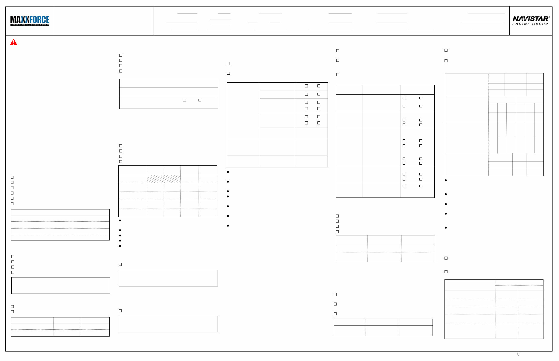
International® MaxxForce™ 5 Hard Start and No Start Diagnostics To prevent personal injury or death, read all safety instructions in the "Safety Information" section of International MaxxForce 5 Diagnostics Manual EGES-395 before doing procedures on this form. Notes See "Hard Start and No Start Diagnostics" in EGES-395. Use figures and additional information to do each test or procedure. Record results on this form. For starting concerns with ECT temperatures below 16 0 C (60 0 F), do Glow Plug System and Inlet Air Heater System tests as necessary. Do Required Test Procedures in sequence and do Special Test Procedures when needed. Doing a test out of sequence could cause incorrect results. If a problem was found and corrected, it is not necessary to complete the rest of the form unless a starting concern remains. See EGES-395 Appendix A for Performance Specifications and Appendix B for Diagnostic Trouble Codes (DTCs). WARNING Check for WAIT TO START lamp Check amber WATER IN FUEL lamp Listen for injector precycle. Listen for hum or buzz from electronic fuel pump. 2. Initial Ignition Key On (Do not start) Comments Main Power Relay Voltage to ECM Connect Main Power Relay Breakout Harness between the ECM main power relay and distribution box. Crank engine and use a DMM to measure voltage to ECM. (Min 130 rpm for 20 seconds) Check voltage between connector Pin 87 and ground. DMM Instrument Spec Actual 6.2 KOEO Injector Test Use EST to run KOEO Injector Test. Correct problem causing active DTCs before continuing. Active DTCs 6.1 KOEO Standard Test Use EST to run KOEO Standard Test Correct problem causing active DTCs before continuing. Active DTCs Inlet Air Heater System Install Amp Clamp around feed wire and use EST to do Output State Test for Inlet Air Heater. After 4 seconds, measure amperage for heater wire. If Amperage draw test results are within specification, do not continue testing the Inlet Air Heater System. Test Amperage draw Voltage at Element Resistance or Element Wiring harness continuity and resistance Relay operation Battery feed Relay output Air Heater Wire Circuit Spec 45 to 70 Amps BAT V < 5 ohms < 5 ohms 4. ECM Calibration, DTCs, and Sensor Values Install Electronic Service Tool (EST). Record ECM calibration _________________________ Use EST to read Diagnostic Trouble Codes (DTC). Use EST to check KOEO values for temperature and pressure sensors. Yes No Abnormal sensor values Suspect sensor/value Active DTCs Inactive DTCs Correct problems causing active DTCs and abnormal sensor values before continuing. EGR Valve Operation Output State Test Low High EGR valve actual Run KOEO Output State Test Low. Enter data from Output State Test Low. Run KOEO Output State Test High. Enter data from Output State Test High. Check Performance Specifications and repair EGR problems before continuing. Fuel System Measure pressure at the secondary fuel filter housing test port. Remove EFP switch for access. If concerns were not found in Pressure, Quality, and Aerated Fuel test, do not continue testing fuel system. Spec Actual Pressure, Quality, and Aerated Fuel Hear pump running Fuel in tank First sample Aerated fuel Contaminated fuel Second sample (if needed) Aerated fuel Contaminated fuel Fuel pressure KOEO Fuel Pump Discharge Pressure Fuel Pump Inlet Restriction Spec Actual Discharge pressure Spec Actual Restriction Yes No Yes No Yes No Yes No Yes No Yes No If a hum can not be heard from the HFCM, verify fuel pump is being powered. Repair as necessary. If fuel has air bubbles, check for leaks in supply lines - tank to HFCM. If fuel is contaminated, correct problem. If fuel pressure is low or slow to build, replace both fuel filters and retest. If fuel pressure is below specification, do Fuel Pump Discharge Pressure test. If pump discharge pressure is in specification, inspect fuel regulator valve. If discharge pressure is low or slow to build, do Fuel Inlet Restriction test. Low ICP test ICP System Function Audible air leak? Audible air leak? Audible air leak? Over 3.45 Mpa (500 psi) (0.82V)? Left Right Over 3.45 Mpa (500 psi) (0.82V)? IPR connectors: Corroded, bent or pushed back pins IPR Function Under Valve Cover ICP Leaks Cylinder Head Isolation High-pressure Pump Cylinder Head Crankcase Left Right Left Right Unplugged B+ applied Yes No Yes No Yes Yes No No No No Yes Yes No No Yes Yes No No Yes Yes Yes No Question Result Low ICP System Pressure Do the following tests, if ICP was not to spec during Test 5. Start and continue ICP System Function test, if lube oil pressure is above min spec and terminals on the IPR valve and engine harness are not damaged or corroded. If IPR connector pins are corroded, bent, or pushed back: do not do remaining test procedures for Low ICP. Glow Plug System Use EST to do Output State Test for glow plugs. After 9 seconds, measure amperage and check for DTCs. If test results in Glow Plug System Amperage are within specification, do not continue testing the glow plug system. Glow Plug System Amperage Glow Plug Harness to Ground Spec 0.1 - 6 ohms Glow Plug to Ground Spec 0.1 - 6 ohms Engine Harness 3-pin to Relay Spec < 5 ohms Relay Operation Cylinder Head Spec Actual Left Right 30-42 amps 30-42 amps Glow plugs L Glow plugs R Yellow Red White White Red Battery feed Relay output Spec Actual B+ B+ If Glow Plug System Amperage readings are not within spec, do Glow Plug Harness to Ground test for all glow plugs out of spec. If results of Glow Plug System Amperage are 0 amps for both cylinder heads, do Relay Operation test. If results of Glow Plug Harness to Ground test are within spec, do test Engine Harness 3-pin to Relay. If results of Glow Plug Harness to Ground are not within spec, do Glow Plug to Ground test for all glow plugs out of spec. If results of Glow Plug to Ground test are within spec, replace failed glow plug harness. If results are not within spec, replace glow plugs that are out of spec. 6 3 5 2 4 1 Yellow Terminal 5. EST Data List Enter data in the KOEO spec and Cranking spec columns. Monitor KOEO values and enter in KOEO actual column. Crank engine and monitor DATA for 20 seconds. Enter data in the Cranking actual column. See International MaxxForce 5 Diagnostic Manual “Appendix A Performance Specifications” If VBAT voltage is below spec, do Main Power Relay Voltage to ECM test. If no rpm is noted, check DTCs. If ICP is below spec, do Low ICP System Pressure test. If fuel pressure is low, do Fuel System test. If EGRP is out of spec, see EGDP Sensor in Section 7. PID VBAT RPM ICP EFP EGRP KOEO actual Cranking actual KOEO spec Cranking spec 0 1. Visual Inspection Engine Oil Level. Fuel Level. Engine Coolant Level. Electrical System. Exhaust System. Intake Air System and Charge Air Cooler (CAC). Check Oil level Fuel level Actual Coolant level Air filter restriction gauge Required Test Procedures Special Test Procedures International MaxxForce 5 Diagnostic Form EGED-400 B+ B+ Beginning with 2007 Model Year Date Unit No. Technician Miles Hours VIN Truck build Manual Transmission Auto Ambient temperature Coolant temperature Complaint Kilometers Engine SN Engine HP Engine Family Rating Code ECM calibration Injector No. Turbocharger No. Navistar, Inc. 2008 c EGR valve spec > 7 V 3. Engine Cranking Check cranking rpm. (Instrument panel) Check cranking battery voltage. Check Cranking rpm Cranking battery voltage Spec Actual 0 % 0 % > 9 V
Navistar Maxxforce 5 Engine Full Service & Repair Manual
This is a complete factory service repair workshop manual with no extra fees or expiry dates. It is available for instant access on your computer, tablet, or smartphone.
This professional manual covers all repairs, servicing, and troubleshooting procedures. It contains hundreds of pages with detailed photos and diagrams, providing step-by-step instructions and highly detailed exploded diagrams and pictures used by professional mechanics and technicians.
Can I print out a page?
Yes, you can print out a single page or the entire manual, as per your choice.
Can I use this manual on more than one computer?
Yes, this manual can be used on as many computers as required.
Is this a trial or a limited version?
No, this is the full manual without any limitations or trial periods and can be used for life.
Will this manual expire in 12 months or will I have to pay a renewal fee?
No, absolutely not! You can continue to use this manual for life without the need to renew or pay any extra.
Will this manual work on Windows & MAC computers?
Yes, it is fully compatible with all Windows & all MAC computers.
Thanks for looking at this item, please click on the button.
Recently Viewed
5,521,897Happy Clients
2,594,462eManuals
1,120,453Trusted Sellers
15Years in Business
Price:
Actual Price:
Navistar Maxxforce 5 Engine Full Service & Repair Manual