

MTD AC3 Series 4-Cycle Engines OEM Service & Repair Manual
What's Included?
Fast Download Speeds
Online & Offline Access
Access PDF Contents & Bookmarks
Full Search Facility
Print one or all pages of your manual

Professional Shop Manual
AC3 Series of 4-Cycle Engines
NOTE: These materials are for use by trained technicians who are experienced in the service and repair of outdoor power
equipment of the kind described in this publication, and are not intended for use by untrained or inexperienced individuals.
These materials are intended to provide supplemental information to assist the trained technician. Untrained or inexperi-
enced individuals should seek the assistance of an experienced and trained professional. Read, understand, and follow all
instructions and use common sense when working on power equipment. This includes the contents of the product’s Oper-
ators Manual, supplied with the equipment. No liability can be accepted for any inaccuracies or omission in this publication,
although care has been taken to make it as complete and accurate as possible at the time of publication. However, due to
the variety of outdoor power equipment and continuing product changes that occur over time, updates will be made to these
instructions from time to time. Therefore, it may be necessary to obtain the latest materials before servicing or repairing a
product. The company reserves the right to make changes at any time to this publication without prior notice and without
incurring an obligation to make such changes to previously published versions. Instructions, photographs and illustrations
used in this publication are for reference use only and may not depict actual model and component parts.
© Copyright 2010 MTD Products Inc. All Rights Reserved
For Parts Call 606-678-9623 or 606-561-4983
www.mymowerparts.com

For Parts Call 606-678-9623 or 606-561-4983
www.mymowerparts.com

I
Chapter 1: Introduction ............................................................................................1
Professional shop manual intent . . . . . . . . . . . . . . . . . . . . . . . . . . . . . . . . . . . . . 1
Fasteners . . . . . . . . . . . . . . . . . . . . . . . . . . . . . . . . . . . . . . . . . . . . . . . . . . . . . . 1
Assembly . . . . . . . . . . . . . . . . . . . . . . . . . . . . . . . . . . . . . . . . . . . . . . . . . . . . . . . 2
Description . . . . . . . . . . . . . . . . . . . . . . . . . . . . . . . . . . . . . . . . . . . . . . . . . . . . . 2
Identifying engines . . . . . . . . . . . . . . . . . . . . . . . . . . . . . . . . . . . . . . . . . . . . . . . 2
Model and serial numbers . . . . . . . . . . . . . . . . . . . . . . . . . . . . . . . . . . . . . . . . . . 4
Chapter 2: Maintenance ...........................................................................................5
Maintenance . . . . . . . . . . . . . . . . . . . . . . . . . . . . . . . . . . . . . . . . . . . . . . . . . . . . 5
Oil . . . . . . . . . . . . . . . . . . . . . . . . . . . . . . . . . . . . . . . . . . . . . . . . . . . . . . . . . . . . 5
Changing the oil . . . . . . . . . . . . . . . . . . . . . . . . . . . . . . . . . . . . . . . . . . . . . . . . . 5
Spark plugs . . . . . . . . . . . . . . . . . . . . . . . . . . . . . . . . . . . . . . . . . . . . . . . . . . . . . 6
Air filter . . . . . . . . . . . . . . . . . . . . . . . . . . . . . . . . . . . . . . . . . . . . . . . . . . . . . . . . 7
Spark arrestor . . . . . . . . . . . . . . . . . . . . . . . . . . . . . . . . . . . . . . . . . . . . . . . . . . . 8
Fuel filer . . . . . . . . . . . . . . . . . . . . . . . . . . . . . . . . . . . . . . . . . . . . . . . . . . . . . . . 9
Valve lash . . . . . . . . . . . . . . . . . . . . . . . . . . . . . . . . . . . . . . . . . . . . . . . . . . . . . 10
Chapter 3: Troubleshooting .................................................................................. 11
Definitions . . . . . . . . . . . . . . . . . . . . . . . . . . . . . . . . . . . . . . . . . . . . . . . . . . . . . 11
Introduction . . . . . . . . . . . . . . . . . . . . . . . . . . . . . . . . . . . . . . . . . . . . . . . . . . . . 11
Steps to troubleshooting . . . . . . . . . . . . . . . . . . . . . . . . . . . . . . . . . . . . . . . . . . 11
Identify factors that could cause the problem . . . . . . . . . . . . . . . . . . . . . . . . . . 13
Repairing the problem . . . . . . . . . . . . . . . . . . . . . . . . . . . . . . . . . . . . . . . . . . . . 17
Diagnostic tests . . . . . . . . . . . . . . . . . . . . . . . . . . . . . . . . . . . . . . . . . . . . . . . . . 17
Prime test . . . . . . . . . . . . . . . . . . . . . . . . . . . . . . . . . . . . . . . . . . . . . . . . . . . . . 18
Compression testing . . . . . . . . . . . . . . . . . . . . . . . . . . . . . . . . . . . . . . . . . . . . . 19
Chapter 4: Ignition ................................................................................................. 21
Troubleshooting the Ignition System . . . . . . . . . . . . . . . . . . . . . . . . . . . . . . . . . 21
Testing the module . . . . . . . . . . . . . . . . . . . . . . . . . . . . . . . . . . . . . . . . . . . . . . 22
Test the engine stop switch . . . . . . . . . . . . . . . . . . . . . . . . . . . . . . . . . . . . . . . . 23
Module . . . . . . . . . . . . . . . . . . . . . . . . . . . . . . . . . . . . . . . . . . . . . . . . . . . . . . . 24
Flywheel . . . . . . . . . . . . . . . . . . . . . . . . . . . . . . . . . . . . . . . . . . . . . . . . . . . . . . 25
Chapter 5: Fuel system and carburetor ............................................................... 27
Inspecting the fuel: . . . . . . . . . . . . . . . . . . . . . . . . . . . . . . . . . . . . . . . . . . . . . . 28
Test fuel for alcohol . . . . . . . . . . . . . . . . . . . . . . . . . . . . . . . . . . . . . . . . . . . . . . 28
Fuel tank . . . . . . . . . . . . . . . . . . . . . . . . . . . . . . . . . . . . . . . . . . . . . . . . . . . . . . 30
Fuel lines . . . . . . . . . . . . . . . . . . . . . . . . . . . . . . . . . . . . . . . . . . . . . . . . . . . . . . 31
Carburetor . . . . . . . . . . . . . . . . . . . . . . . . . . . . . . . . . . . . . . . . . . . . . . . . . . . . . 32
Troubleshooting the carburetor . . . . . . . . . . . . . . . . . . . . . . . . . . . . . . . . . . . . . 35
Disassembly of the carburetor . . . . . . . . . . . . . . . . . . . . . . . . . . . . . . . . . . . . . . 37
Re-assembly of the carburetor . . . . . . . . . . . . . . . . . . . . . . . . . . . . . . . . . . . . . 39
Carburetor insulator . . . . . . . . . . . . . . . . . . . . . . . . . . . . . . . . . . . . . . . . . . . . . 41
Table of Contents
For Parts Call 606-678-9623 or 606-561-4983
www.mymowerparts.com

II
Chapter 6: Starters ................................................................................................. 43
Recoil Starter Removal . . . . . . . . . . . . . . . . . . . . . . . . . . . . . . . . . . . . . . . . . . . 43
The starter rope, pulley and springs . . . . . . . . . . . . . . . . . . . . . . . . . . . . . . . . . 44
Electric starter system . . . . . . . . . . . . . . . . . . . . . . . . . . . . . . . . . . . . . . . . . . . . 48
Chapter 7: Clutch and Upper Drive Shaft ............................................................ 49
Upper drive shaft assembly . . . . . . . . . . . . . . . . . . . . . . . . . . . . . . . . . . . . . . . . 49
Clutch Removal/replacement . . . . . . . . . . . . . . . . . . . . . . . . . . . . . . . . . . . . . . . 51
Chapter 8: Engine assembly .................................................................................. 53
Engine disassembly . . . . . . . . . . . . . . . . . . . . . . . . . . . . . . . . . . . . . . . . . . . . . 54
Engine Reassembly . . . . . . . . . . . . . . . . . . . . . . . . . . . . . . . . . . . . . . . . . . . . . 59
For Parts Call 606-678-9623 or 606-561-4983
www.mymowerparts.com

Introduction
1
Professional Shop Manual intent
This Manual is intended to provide service dealers with an introduction to the mechanical aspects of the AC3
series of 4-cycle engines.
Disclaimer: The information contained in this manual is correct at the time of writing. Both the product and the infor-
mation about the product are subject to change without notice.
About the text format:
NOTE: is used to point out information that is relevant to the procedure, but does not fit as a step in the proce-
dure.
• Bullet points: indicate sub-steps or points.
Disclaimer: This manual is intended for use by trained, professional technicians.
• Common sense in operation and safety is assumed.
• In no event shall MTD be liable for poor text interpretation or poor execution of the procedures described
in the text.
• If the person using this manual is uncomfortable with any procedures they encounter, they should seek
the help of a qualified technician or MTD Technical Support.
Fasteners
• Most of the fasteners used on the engine are metric. Some are sized in fractional inches. For this reason,
wrench sizes are frequently identified in the text, and measurements are given in U.S. and metric scales.
• If a fastener has a locking feature that has worn, replace the fastener or apply a small amount of releas-
able thread locking compound such as Loctite® 242 (blue).
• Some fasteners like cotter pins are single-use items that are not to be reused. Other fasteners such as
lock washers, retaining rings, and internal cotter pins (hairpin clips) may be reused if the do not show
signs of wear or damage. This manual leaves that decision to the judgement of the technician.
Caution is used to point out potential danger to the technician, operator, bystanders, or sur-
rounding property. ! CAUTION
Warning indicates a potentially hazardous situation that, if not avoided, could result in death
or serious injury. ! WARNING ! DANGER
Danger indicates an imminently hazardous situation that, if not avoided, will result in death or
serious injury. This signal word is to be limited to the most extreme situations
CHAPTER 1: INTRODUCTION
For Parts Call 606-678-9623 or 606-561-4983
www.mymowerparts.com
AC3 Series of engines
2
Assembly
Torque specifications may be noted in the text that covers assembly, they may also be summarized in tables
along with special instructions regarding locking or lubrication. Whichever method is more appropriate will be used.
In many cases, both will be used so that the manual is handy as a quick-reference guide as well as a step-by-step
procedure guide that does not require the user to hunt for information.
The level of assembly instructions provided will be determined by the complexity and of reassembly, and by the
potential for unsafe conditions to arise from mistakes made in assembly.
Some instructions may refer to other parts of the manual for subsidiary procedures. This avoids repeating the same
procedure two or three times in the manual.
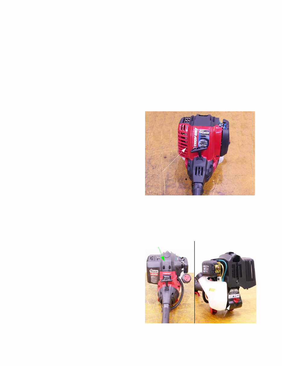
Description
The AC3 engine is used on a variety of handheld equip-
ment. This engine has:
• 29cc’s of displacement.
• A cantilever crank design.
• Pushrod activated OHV.
• Genuine 4-cycle design, not a hybrid 2-cycle/4-
cycle like Stihl and Shindaiwa.
• Engine covers split front and back.
Currently there are engine models in this series of
engine:
• AC3
• AC3.1
• AC3.2
The AC3 version has an 8 to 1 compression ratio. The AC3.1 and the AC3.2 have a 9 to 1 compression ratio
which increased power approximately 20%. The AC3.1 and 3.2 engines are also available with electric start versions.
Identifying engines
AC2
• 26 cc’s of displacement.
• Engine cover surrounds the cylinder head and
muffler.
Visible from the rear:
• A plastic, diagonal split crankcase sump.
• A dip stick that threads into the sump.
Figure 1.1
AC3 engine
Figure 1.2
Plastic sump
Full engine cover
For Parts Call 606-678-9623 or 606-561-4983
www.mymowerparts.com
Introduction
3
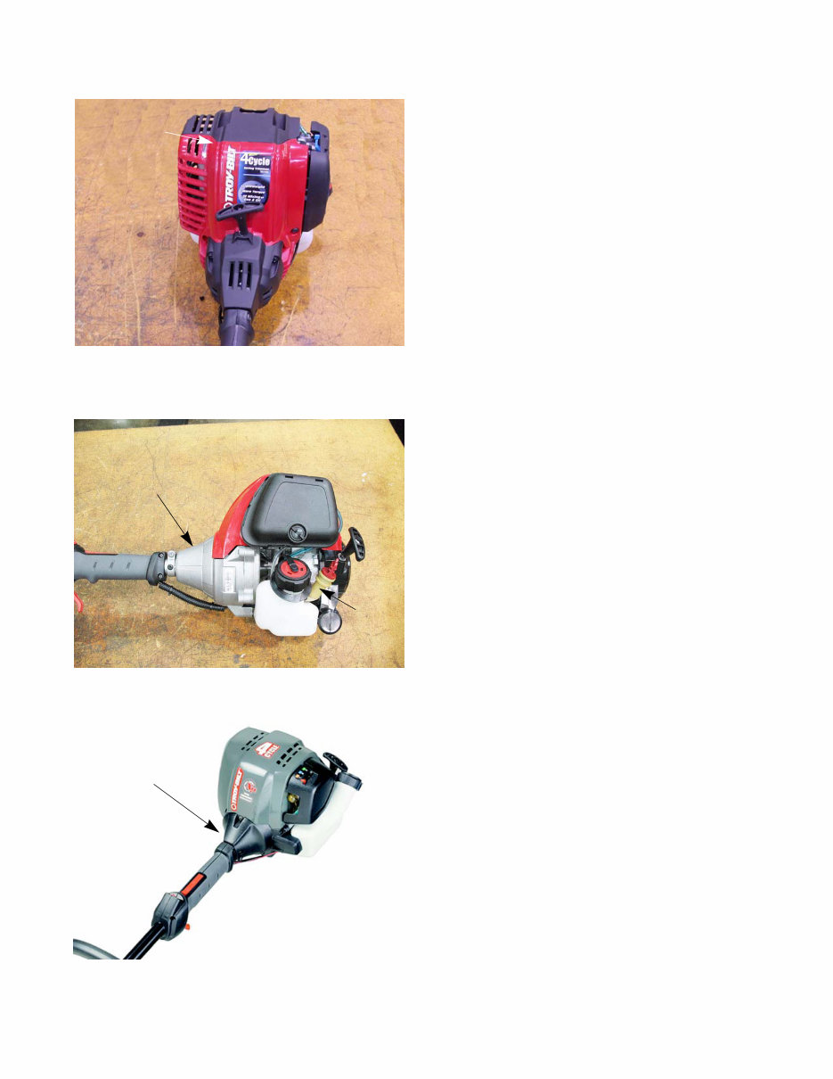
AC3
• 29cc’s of displacement.
• Engine covers split front and back.
• Metal sump
AC4
• 32 cc’s of displacement.
• Aluminum clutch housing.
• Extended oil fill tube that is near the carburetor.
• End mounted recoil starter.
AC5
• 25 cc’s of displacement.
• Identical to the AC4 except for the plastic clutch
housing.
Figure 1.3
Engine cover
splits front to
back
Figure 1.4
Aluminum clutch housing
oil
fill
tube
Figure 1.5
Plastic clutch
housing
For Parts Call 606-678-9623 or 606-561-4983
www.mymowerparts.com

AC3 Series of engines
4
Model and Serial Numbers
The model (item) and serial number are on a little
white sticker with bar code. These are the numbers
needed when ordering parts. This sticker can be found on
the side of the engine.
The model number is 41ADT59C711. The break down of what the number mean is as follows:
41 ............................................................................................ Hand held product
........A...................................................................................... Sales level
........... D.................................................................................. Product type
.................T59 ......................................................................... Unique Identifier
.........................C..................................................................... Packaging code
.............................711.............................................................. Customer number
The serial number is 1F296DZ0060. The serial number reads as follows:
1 .............................................................................................. Engineering level
..F ............................................................................................ Month of production (F = June)
.....29 ....................................................................................... Day of the month
.........6 ..................................................................................... Last digit of the year
...........D................................................................................... Plant it was built in (MTD Southwest)
..............Z ................................................................................ Assembly line number
.................0060 ....................................................................... Number of unit built
Figure 1.6
Model number
Serial number
For Parts Call 606-678-9623 or 606-561-4983
www.mymowerparts.com
Maintenance
5
MAINTENANCE
The information in this manual applies to the AC3 series of engines. Some basic principles may apply to engines
produced by other manufacturers.
As the saying goes “an ounce of prevention is worth a pound of cure”. The same can be said about preventive
maintenance on outdoor power equipment. By changing the spark plug, air filter, and oil at recommended intervals
many failures can be avoided. Sometimes just clearing off yard debris that has collected through use can make the
difference between a properly running piece of equipment and the expensive inconvenience of unplanned repairs.
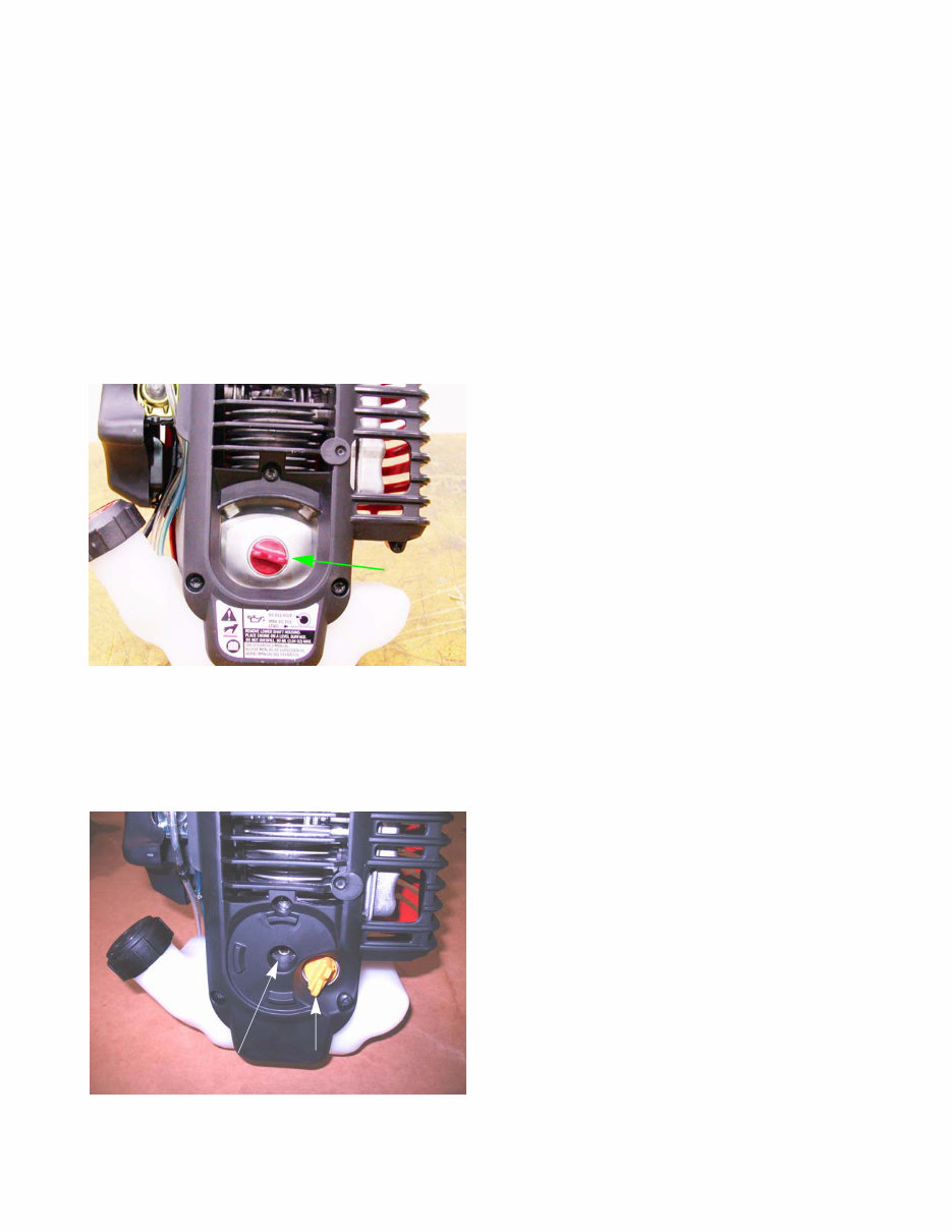
Oil
To check the oil:
1. Clean around the oil plug.
2. Place the trimmer on a level surface.
3. Unscrew the oil plug. See Figure 2.1.
4. The oil should be level with the bottom of the threads.
NOTE: If needed, add oil slowly until oil level is even with
the bottom of the threads.
5. Tighten oil plug finger tight.
Changing the oil
The first oil change should be done at 10 hours and then it should be changed every 25 hours or at the start of the
season.
To change the oil:
1. Clean around the oil plug.
2. Remove the oil plug. See Figure 2.2.
3. Tip the trimmer to the side and drain the oil in a safe,
approved container.
4. Disposed of the used oil by following the federal,
state and local regulations.
5. Fill the engine with 3.04 fluid ounces (90 ml) of SAE
30 oil that meets or exceeds API SM standards.
NOTE: The spark arrestor should be cleaned and the
valves adjusted at every oil change.
Figure 2.1
Oil plug
Figure 2.2
Oil plug
Electric start
coupler
CHAPTER 2: MAINTENANCE
For Parts Call 606-678-9623 or 606-561-4983
www.mymowerparts.com
AC3 Series of engines
6
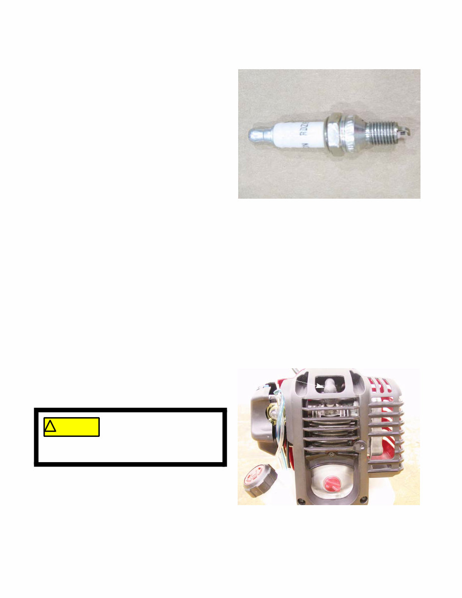
Spark plugs
The spark plug used in the 32cc trimmer is a Cham-
pion RDZ19H gapped to 0.025” (.655 mm).
See Figure 2.3.
Wear rate will vary with severity of use. If the edges of
the center electrode are rounded-off, or any other appar-
ent wear / damage occurs, replace the spark plug before
operating failure (no start) occurs.
Cleaning the spark plug:
NOTE: We do not recommend cleaning spark
plugs.
• Use of a wire brush may leave metal deposits
on the insulator that causes the spark plug to
short out and fail to spark.
• Use of abrasive blast for cleaning may cause
damage to ceramic insulator or leave blast
media in the recesses of the spark plug.
• When the media comes loose during engine operation, severe and non-warrantable engine damage may
result.
Inspection of the spark plug can provide indications of the operating condition of the engine.
• Light tan colored deposits on insulator and electrodes is normal.
• Dry, black deposits on the insulator and electrodes indicate an over-rich fuel / air mixture (too much fuel or
not enough air)
• Wet, black deposits on the insulator and electrodes indicate the presence of oil in the combustion cham-
ber.
• Heat damaged (melted electrodes / cracked insulator / metal transfer deposits) may indicate detonation.
• A spark plug that is wet with fuel indicates that fuel is present in the combustion chamber, but it is not
being ignited.
Spark plug removal and installation
To replace a spark plug:
1. Disconnect the spark plug wire. See Figure 2.4.
2. Remove the spark plug using a 5/8” spark plug
socket.
3. Gap a new plug at 0.025” (.6 mm).
4. Install the spark plug and tighten to a torque of 100 -
110 in. lbs.(11 -12 Nm).
5. Follow steps 1 and 2 in reverse order.
6. Test run the trimmer in a safe area before returning it to service.
Figure 2.3
Figure 2.4
Spark plug wire ! CAUTION
Do not grab the spark plug wire
with pliers. Damage to the spark-
plug boot will result. A damaged
spark plug boot will weaken the spark of the spark
plug.
For Parts Call 606-678-9623 or 606-561-4983
www.mymowerparts.com
You're Reading a Preview
What's Included?
Fast Download Speeds
Online & Offline Access
Access PDF Contents & Bookmarks
Full Search Facility
Print one or all pages of your manual
$30.99
$40.99
Viewed 16 Times Today


Secure transaction
What's Included?
Fast Download Speeds
Online & Offline Access
Access PDF Contents & Bookmarks
Full Search Facility
Print one or all pages of your manual
$30.99
$40.99
- MTD AC3 Series 4-Cycle Engines Service & Repair Manual is a comprehensive technical guide for engine service, maintenance, troubleshooting, and replacement procedures.
- It includes step-by-step instructions, clear images, and exploded-view illustrations, making it suitable for professional mechanics and DIY enthusiasts.
- Table of Contents:
- Chapter 1: Introduction
- Chapter 2: Maintenance
- Chapter 3: Troubleshooting
- Chapter 4: Ignition
- Chapter 5: Fuel system and carburetor
- Chapter 6: Starters
- Chapter 7: Clutch and Upper Drive Shaft
- Chapter 8: Engine assembly
- This manual is not a generic repair guide but the manufacturer-sourced OEM manual used by professional technicians.
- It contains detailed troubleshooting and replacement procedures, along with clear images and exploded-view illustrations.
- The manual is easily accessible, searchable, and printable, compatible with various electronic devices, and requires Adobe Reader for access.


