

Mitsubishi 6M60 Diesel Engine Service Repair Manual
What's Included?
Fast Download Speeds
Online & Offline Access
Access PDF Contents & Bookmarks
Full Search Facility
Print one or all pages of your manual

Service Manual
99709-51100 For use with the FD80N-FD160N Service Manuals.
6M60-TL Diesel Engine

GROUP INDEX
00
11
12
13A
13E
14
15
17
54
61
GENERAL ........................................
ENGINE............................................
LUBRICATION .................................
FUEL AND ENGINE CONTROL......
ELECTRONICALLY CONTROLLED
FUEL SYSTEM ..................................
COOLING.........................................
INTAKE AND EXHAUST .................
EMISSION CONTROL .....................
ELECTRICAL...................................
SPECIAL EQUIPMENT ...................
FOREWORD
This Shop Manual is published for the information and
guidance of personnel responsible for maintenance of the
Mitsubishi 6M60-TL series diesel engine, and includes
procedures for adjustment and maintenance services.
We earnestly look forward to seeing that this manual is
made full use of in order to perform correct services with
no wastage.
For more details, please consult your nearest authorized
Mitsubishi forklift truck dealer.
Kindly note that the specifications and maintenance ser-
vice figures are subject to change without prior notice in
line with improvement which will be effected from time to
time in the future.
SEPTEMBER 2006
Applicable models
6M60-TL
(for industrial use)

00-1
13E
13A
GROUP 00 GENERAL
HOW TO READ THIS MANUAL ......................................................... 00-2
ENGINE NUMBER ............................................................................ 00-7
PRECAUTIONS FOR MAINTENANCE OPERATION ....................... 00-8
DIAGNOSTIC CODES
1. Using Multi-Use Tester .............................................................. 00-17
2. Use of Blinking Warning Lamp for Diagnostic Code .................... 00-19
3. Up-Time Service Tool Functions .................................................... 00-21
4. Troubleshooting ............................................................................... 00-29
TABLE OF STANDARD TIGHTENING TORQUES .......................... 00-31
00-2
This manual consists of the following parts:
• Specifications
• Structure and Operation
• Troubleshooting
• General Inspection and Adjustment
• Service procedures
General Inspection and Adjustment
• Procedures for inspection and adjustment of individual parts and assemblies as mounted on the machine are de-
scribed including specific items to check and adjust. Specified or otherwise, inspection should be performed for
looseness, play, backlash, crack, damage, etc.
Service procedure
• Procedures for servicing components and parts off the machine are described centering on key points in their re-
moval, installation, disassembly, reassembly, inspection, etc.
Inspection
• Check items subject to “acceptable/unacceptable” judgement on the basis of service standards are all given.
• Some routine visual checks and cleaning of some reused parts are not described but must always be included in
actual service work.
Caution
• This service manual contains important cautionary instructions and supplementary information under the follow-
ing four headings which identify the nature of the instructions and information:
Terms and Units
• Front and rear
The forward running direction of the machine is referred to as the front and the reverse running direction is re-
ferred to as the rear.
• Left and right
Left hand side and right hand side, when facing the forward running direction of the machine, are respectively left
and right.
Standard value
• Standard value dimensions in designs indicating: the design dimensions of individual parts, the standard clear-
ance between two parts when assembled, and the standard value for an assembly part, as the case may be.
Limit
• When the value of a part exceeds this, it is no longer serviceable in respect of performance and strength and must
be replaced or repaired.
DANGER
Precautions that should be taken in handling potentially dangerous substances
such as battery fluid and coolant additives.
WARNING
Precautionary instructions, which, if not observed, could result in serious injury or
death.
CAUTION
Precautionary instructions, which, if not observed, may result in damage to or de-
struction of equipment or parts.
NOTE
Suggestions or supplementary information for more efficient use of equipment or
better understandings.
HOW TO READ THIS MANUAL
00
00-3
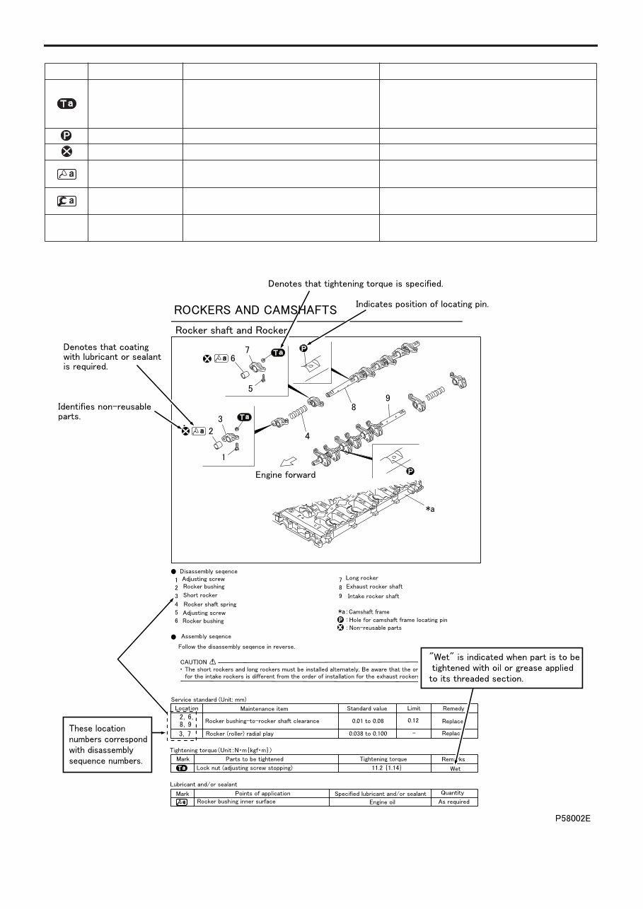
Tightening torque
• Values are directly specified for out-of-standard tightening torques for bolts and nuts.
• Where there is no specified figure for tightening torque, follow the table covering standard tightening torques.
• When the item is to be tightened in a wet state, “wet” is indicated. Where there is no indication, read it as dry.
Units
• Tightening torques and other parameters are given in SI* units with metric units added in brackets { }. Values in
engine specifications, performance curves, and other items taken from official approval documents are given only
in metric units.
*SI: Le Système International d’Unités
Item SI unit {metric unit} Conversion factor
Force N {kgf} 9.80665 N {1 kgf}
Moment of force N·m {kgf·m} 9.80665 N·m {1 kgf·m}
Pressure
Positive pressure kPa {kgf/cm
2
} 98.0665 kPa {1 kgf/cm
2
}
Vacuum pressure
kPa {mmHg} 0.133322 kPa {1 mmHg}
Pa {mmH
2
O} 9.80665 Pa {1 mmH
2
O}
Volume dm
3
{L} 1 dm
3
{1 L}
Heat quantity J {kcal} 4186.05 J {1 kcal}
Heat flow W {kcal/h} 1.16279 W {1 kcal/h}
Power kW {PS} 0.7355 kW {1 PS}
Angle ˚ –
Temperature ˚C –
Electric current A –
Voltage V –
Resistance Ω –
Electric power W –
Unit SI unit Foot-pound unit Conversion rate
Force N (Newton) lbf 1 N = 0.2248 lbf
Moment of force N·m lbf.ft 1 N·m = 0.7375 lbf.ft
Pressure kPa (kilopascal) lbf/in.
2
1 kPa = 0.145 lbf/in.
2
1 kPa = 0.2953 in. Hg
Volume
L
cm
3
cm
3
gal.
oz
cu.in.
1 L = 0.2642 gal. (U.S.)
1 L = 0.220 gal. (Imp.)
1 cm
3
= 0.033814 oz (U.S.)
1 cm
3
= 0.035195 oz (Imp.)
1 cm
3
= 0.061023 cu.in.
Power kW (kilowatt) HP 1 kW = 1.34 HP
Temperature ˚C ˚F t˚C = (1.8t˚C + 32)˚F
Mass quantity of
matter
kg
g
lb
oz
1 kg = 2.2046 lb
1 g = 0.035274 oz
Dimension
m
mm
ft.
in.
1 m = 3.2808 ft.
1 mm = 0.03937 in.
Stress N/cm
2
lbf/in.
2
1 N/cm
2
= 1.45 lbf/in.
2
Example: 390 N·m {40 kgf·m}
Metric unit
SI unit
00-4
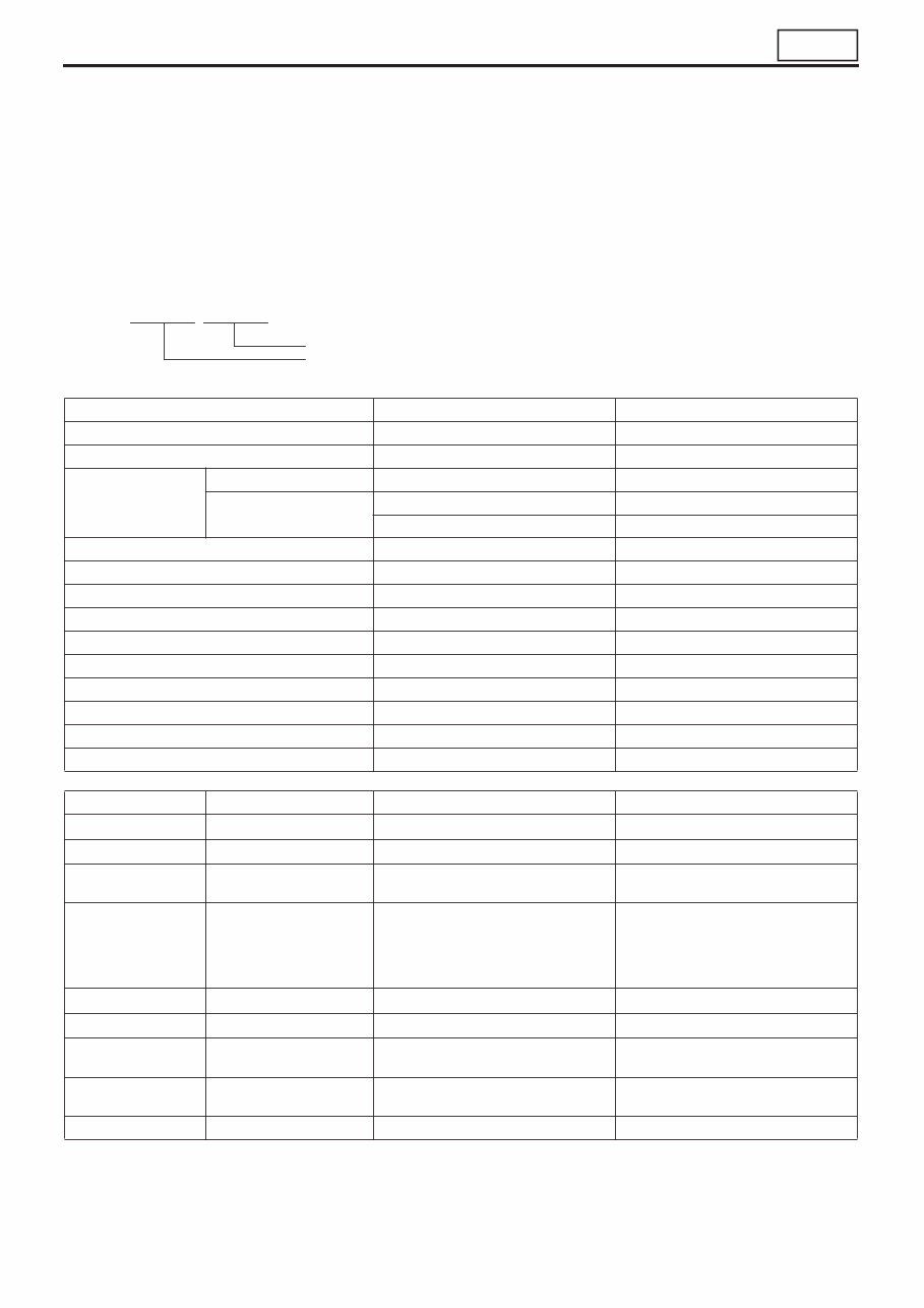
Symbol Denotation Application Remarks
Tightening torque
Parts not tightened to standard torques
(standard torques specified where neces-
sary for servicing)
Specified values shown in table
See Table of Standard Tightening Torques for
parts for which no tightening torques are speci-
fied.
Locating pin Parts to be positioned for installation
Non-reusable parts Parts not to be reused
Lubricant and/or
sealant
Parts to be coated with lubricant or sealant
for assembly or installation
Necessary lubricant and/or sealant, quantity re-
quired, etc. are specified in table.
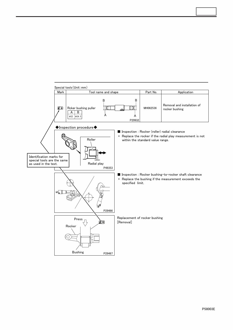
Special tool
Parts for which special tools are required for
service operation
Tool name/shape and part number are shown in
table.
*a Associated part
Parts associated with those removed/disas-
sembled for servicing
HOW TO READ THIS MANUAL
00
00-5
00-6
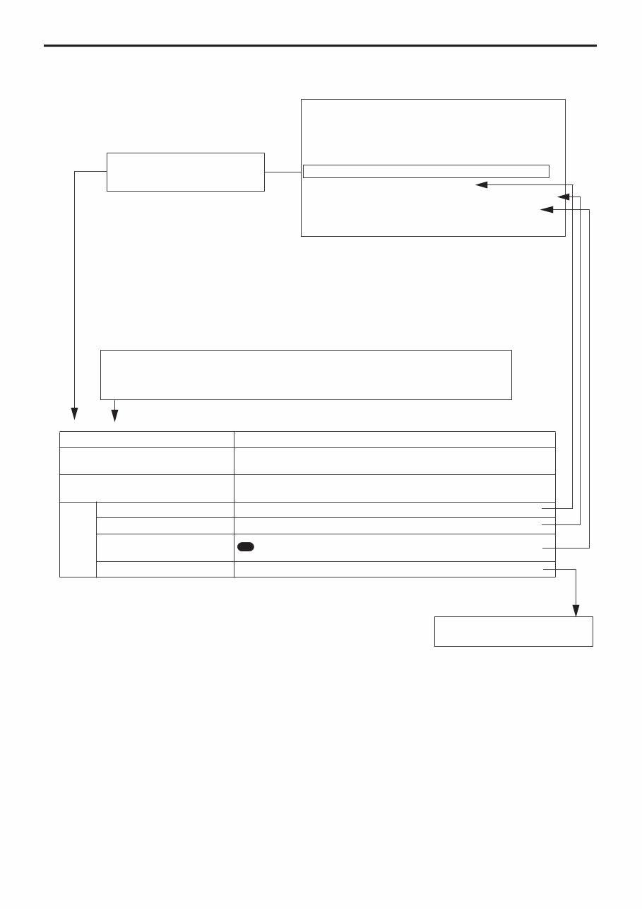
How to Use Diagnostic Codes <Electronically Controlled Fuel System (Gr13E)>
P125A: Common Rail Pressure M/V1 (high) (warning lamp flashes: 63)
Code generation criteria MPROP1 (rail pressure control valve) voltage is above standard valve.
Resetability
System recovers (power is re-supplied to electronic control unit) if signal
becomes normal when starter switch is turned OFF → ON.
Electronic control unit control
• Engine is stopped.
• Exhaust gas recirculation control is stopped.
In-
spec-
tion
item
Service data 0C: Difference Common Rail Pressure
Actuator test B9: Fuel Leak Check
Electronic control unit
connector
: Resistance of MPROP (rail pressure control valve)
Electrical part #574: MPROP1 (rail pressure control valve)
08
This section suggests areas to
inspect for each diagnostic
code.
TROUBLESHOOTING
1. Diagnostic Procedure
2. Diagnostic Precautions
3. Inspections Based On Diagnostic Codes
4. Multi-use Tester Service Data
5. Actuator Tests Performed Using Multi-use Tester
6. Inspections Performed At Electronic Control
Unit Connectors
There are the diagnostic code and message displayed on Multi-Use Tester.
Numerical values in parenthesis are added only when a diagnostic code indicated in
the Multi-Use Tester display differs from the code indicated by the number of warning
lamp flashes.
Refer to “Inspection of Electrical
Equipment.”
The contents of this manual include functions and parts that are not used in your truck depending on
the truck specifications. Please refer to the chassis service manual for the details.
HOW TO READ THIS MANUAL
00
00-7
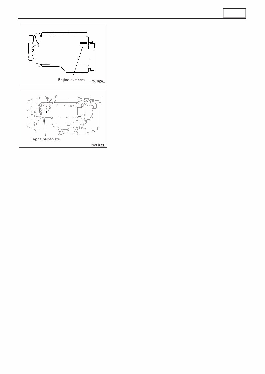
• Serial engine numbers are assigned to the engines in manufac-
turing sequence. Every engine has its own number. These num-
bers are required for registration and related inspection of the
vehicle.
• An engine nameplate indicates the following item.
• Engine model
ENGINE NUMBER
You're Reading a Preview
What's Included?
Fast Download Speeds
Online & Offline Access
Access PDF Contents & Bookmarks
Full Search Facility
Print one or all pages of your manual
$30.99
Viewed 63 Times Today


Secure transaction
What's Included?
Fast Download Speeds
Online & Offline Access
Access PDF Contents & Bookmarks
Full Search Facility
Print one or all pages of your manual
$30.99
This service repair manual is designed for the Mitsubishi 6M60-TL Diesel Engine, specifically for use with the FD80N-FD160N Mitsubishi Forklift Trucks. It includes the following chapters:
- FOREWORD
- GENERAL
- ENGINE
- LUBRICATION
- FUEL AND ENGINE CONTROL
- ELECTRONICALLY CONTROLLED FUEL SYSTEM
- COOLING
- INTAKE AND EXHAUST
- EMISSION CONTROL
- ELECTRICAL
- SPECIAL EQUIPMENT
The manual is available in a printable format and is presented in English.


