HOW TO RE.AD THIS MANUAL HOW THIS MANUAL IS COMPILED . • • • • • . • • . • . . • • . • . . • . . . . ii GENERAL EXPLANATION OF THIS MANUAL . . • • • . . . . . . . . . . iii TERMS AND UNITS . . . . • . • • . • • • • • • • • . . • . . • • • . . • • . • . • . • • . • vii
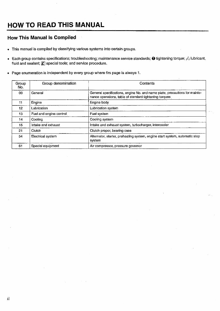
HOW TO READ THIS MANUAL How This Manual Is Compiled • This manual is compiled by classifying various systems into·certain groups. • Each group contains specifications; troubleshooting; maintenance service standards; 0 tightening torque; ~ lubricant, fluid and sealant; ~ special tools; and service procedure. • Page enumeration is independent by every group where firs page is always 1. Group Group denomination Contents No. 00 General General specifications, engine No. and name plate, precautions for mainte- nance operations, table of standard tightening torques 11 Engine Engine body 12 Lubrication Lubrication system 13 Fuel and engine control Fuel system 14 Cooling Cooling system 15 Intake and exhaust Intake and exhaust system, turbocharger, intercooler 21 Clutch Clutch proper, bearing case 54 Electrical system Alternator, starter, preheating system, engine start system, automatic stop system 61 Special equipment Air compressor, pressure governor ii
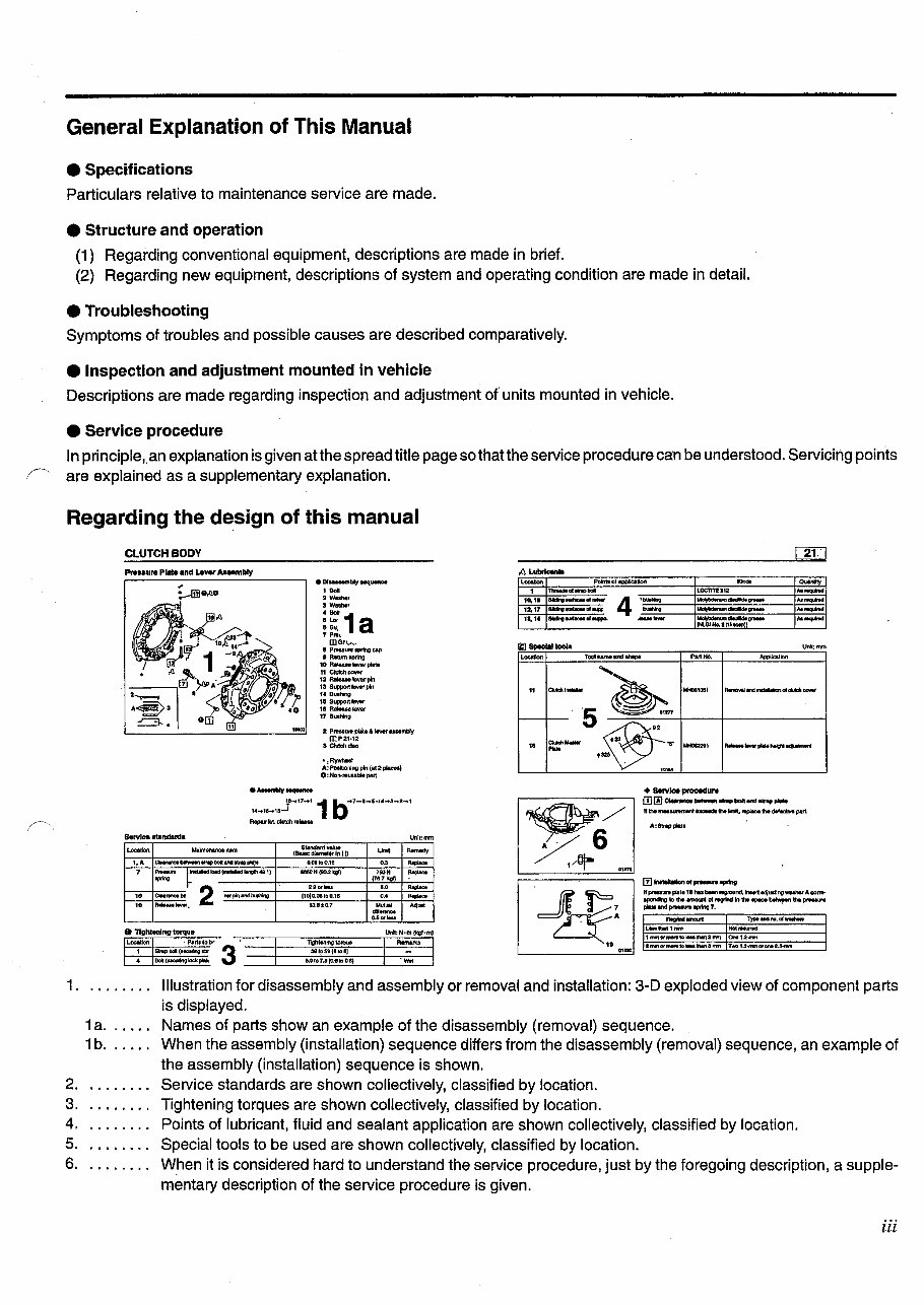
General Explanation of This Manual e Specifications Particulars relative to maintenance service are made. e Structure and operation (1) Regarding conventional equipment, descriptions are made in brief. (2) Regarding new equipment, descriptions of system and operating condition are made in detail. e Troubleshooting Symptoms of troubles and possible causes are described comparatively. e Inspection and adjustment mounted in vehicle Descriptions are made regarding inspection and adjustment of units mounted in vehicle. e Service procedure In principle,. an explanation is given atthe spread title page so that the service procedure can be understood. Servicing points f' are explained as a supplementary explanation. Regarding the design of this manual CLUTCH BODY 21. ·-- • Df.......,.bly Mqutnce 1 eo• 2 W&lher 3W~, 4 eon :~ 1 a 7 Pnu. IDGrv .... 8 Prn~tn IPMg cap D Rlltttnuptltlg 10 Re!ee.M lever pllttl 11 Clutch cover 12R-...klvet'P'n 13 Suppottlevtrpln 14Butllvng 111 SUpport ....... ,. Relauelever 17 Bu.hlng 2 Prnsunt plale & IIYet' UMmbly 0::P21•12 s ClutohcftiC • :Fiyv.hMI A:PoelboBingpln(a12placel) O:Non-,.uub141 patt ,_ 1 10.1• 12.17 11,14 .... ,_ 11 10 Polntlol~tlon """"' """""' 1h'Mdt 111-.p bell LOCTtTE112 ......... Slklno..t..cfNIW 4 ·- ---- ,._. ... SlklnO~crlqil - ---- .. _ ... 81dr!Q..,_ollaJIPO. -- ~=~ ,._. ... TootnamtandiMpe ....... ...,.,., .. --~ MI«MM10!11 ~.s..-....onolcl*"oowr . ~ ~ . 5 - 01f77 -- ~· ""''''" ~---NIItll~ ...... '"' • tlfiM, + Sorv~poocoduro moo.... _ ___ ... __ H the mMIIftmltlt ._. hllmlt, r.p.oe h dlf.XW. part. A:S1rlppla11 Service atandarda Unlt:mm ~( ,Alj- '"" looallon ... ..._....... , ............ Uml1 """""' (BIMc d~mettf In I D ..• CIN-~Ihpboltlndlhflpl.l,. O.Oito0.1fl ,. - 7 :.::- -~lniU!IItdto.d(..w.dllct;lh401) IMON!90.211g!} , ... - (787tgl) a tor._. 5.0 - ,. CIMnnot bt 2 "'pO'l and iiW*Ig (tOJO.oatao.te OA - 10 --. 13.1!1:t0.7 ·~"" ~"" .,_ rn- .. -- lfpteatnp(at• tl hu bNn r.ground, inHrt ~Uitlngwut.r" ACXI~ IIPO"dlnglobamotnOI~il'athll~~hptM&UI'lt .,... and prM&UN IPflna 7. . 0.6Gf ..... ~MIOII"II: lpMdi'KIO.ufWI!It*l ~: 0 'Tightening torque Unii!N·m{kgf·ll'l) lAMfllf11nm Not~ 11M'10f...,...IO.._fllf12mn 0..1.2-fiWn """''" 1 • 1. . ...... . 1a. 1b. 2 ........ . 3 ........ ' 4 ..... ' ... 5. 6. ,. ..... · Parlftobl' 3 l\ghllollmgtorque - Strtpbol(MC:UflnoiU'I 3111~511{41011J Bolt(INCUIIrlglodcpW!. Ulo:>7~(0.G.,OI!} ·- lfNI'IOt,._lo._...,,mn Two1.2-«<mor-2.3-rnm Illustration for disassembly and assembly or removal and installation: 3-D exploded view of component parts is displayed. Names of parts show an example of the disassembly (removal) sequence. When the assembly (installation) sequence differs from the disassembly (removal) sequence, an example of the assembly (installation) sequence is shown. Service standards are shown collectively, classified by location. Tightening torques are shown collectively, classified by location. Points of lubricant, fluid and sealant application are shown collectively, classified by location. Special tools to be used are shown collectively, classified by location. When it is considered hard to understand the service procedure, just by the foregoing description, a supple- mentary description of the service procedure is given. iii
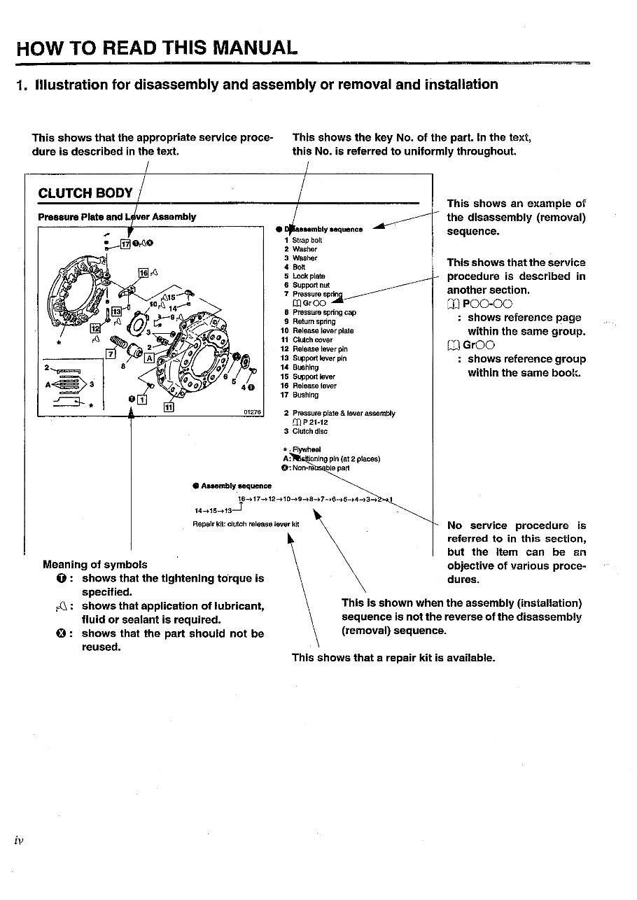
HOW TO READ THIS MANUAL 1. Illustration for disassembly and assembly or removal and installation iv This shows that the appropriate service proce- dure is described in the text. CLUTCH BODY Pressure Plate and L ver Assembly • Assembly sequence This shows the key No. of the part. In the text, this No. is referred to uniformly throughout. • 1 Strap bolt 2 Washer 3 Washer 4 Bo~ 5 lockplate 6 Support nut 7 Pressure sprin [I)GrOO 8 Pre-ssure spring cap 9 Retum spring 10 Release lever plate 11 Clutch cover 12 Release lever pin 13 Support lever pin 14 Bushing 15 Support lever 16 Release lever 17 Bushing •. Flywheel A: · ionlng pin (at 2 places) 0: Non-re ble part This shows an example of the disassembly (removal) sequence. This shows that the service procedure Is described in another section. Cl)P00-00 : shows reference page within the same group. [J]GrOO shows reference group within the same boolt. 16-.17 -.12-.10-.9-.a ... 1 -.a-.s-.4-.3-. 14-.15-.13_1 Repair kit: clutch release lever kit No service procedure is referred to in this section, but the item can be an objective of various proce- dures. Meaning of symbols 0 : shows that the tightening to·rque is specified. ~ : shows that application of lubricant, fluid or sealant is required. 0 : shows that the part should not be reused. This is shown when the assembly (installation) sequence is not the reverse of the disassembly (removal) sequence. This shows that a repair kit is available.
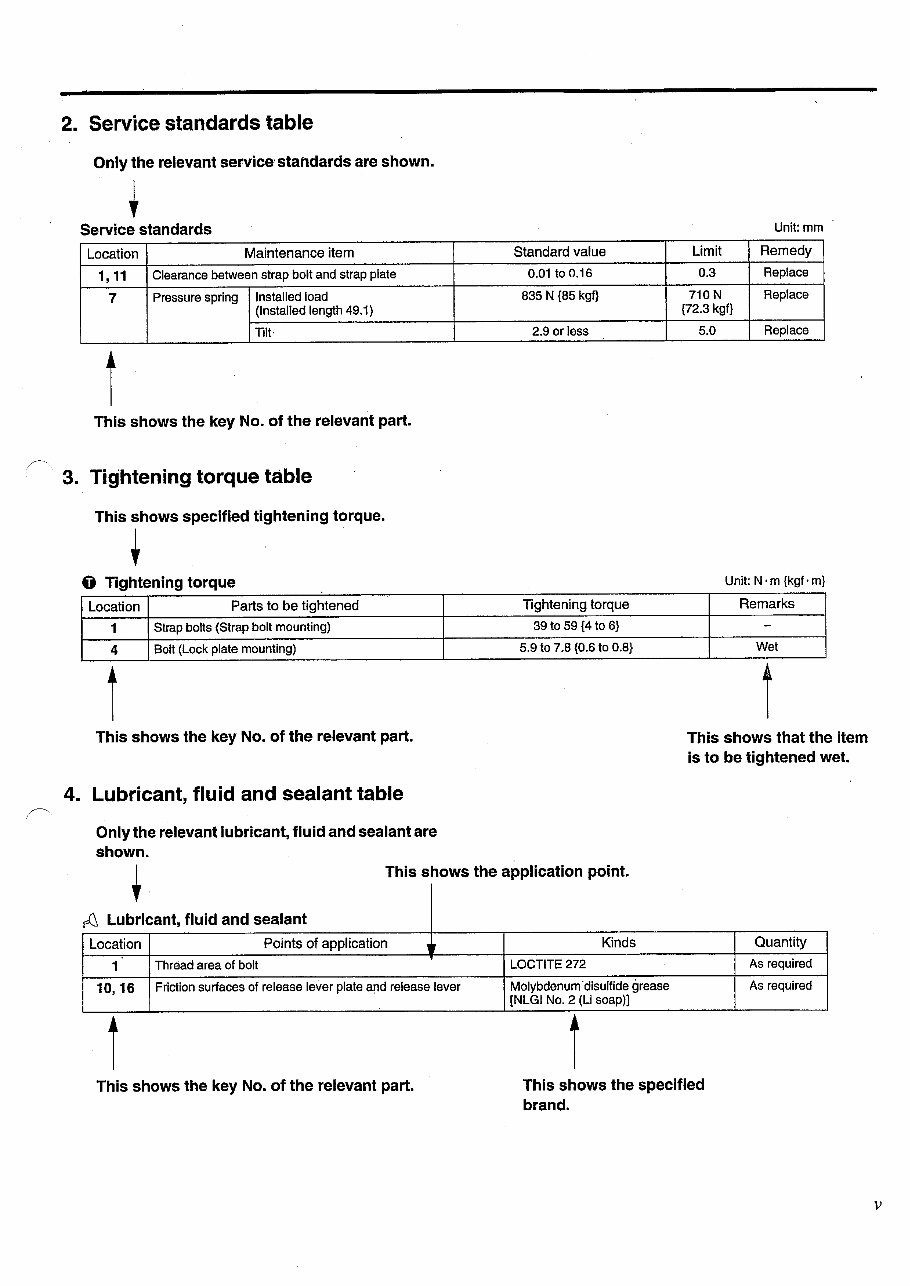
2. Service standards table Only the relevant service· standards are shown. Service standards Location Maintenance item 1' 11 Clearance between strap bolt and strap plate 7 Pressure spring Installed load (Installed length 49.1) lilt· t This shows the key No. of the relevant part. 3. Tightening torque table This shows specified tightening torque. t 0 Tightening torque Location Parts to be tightened 1 Strap bolts (Strap bolt mounting) 4 Bolt (Lock plate mounting) t This shows the key No. of the relevant part. 4. Lubricant, fluid and sealant table Only the relevant lubricant, fluid and sealant are shown. Standard value 0.01 to 0.16 835 N {85 kgf} 2.9 or less Tightening torque 39 to 59 {4 to 6} 5.9 to 7.8 {0.6 to 0.8} Unit: mm Limit Remedy 0.3 Replace 710 N Replace {72.3 kgf} 5.0 Replace Unit: N · m {kgf · m} Remarks - Wet t This shows that the item is to be tightened wet. This shows the application point. ~ Lubricant, fluid and sealant Location Points of application 1 1 Thread area of bolt 10,16 Friction surfaces of release lever plate a!ld release lever t This shows the key No. of the relevant part. Kinds LOCTITE272 Molybdenum ·disulfide grease [NLGI No.2 (Li soap)] t This shows the specified brand. Quantity As required As required v
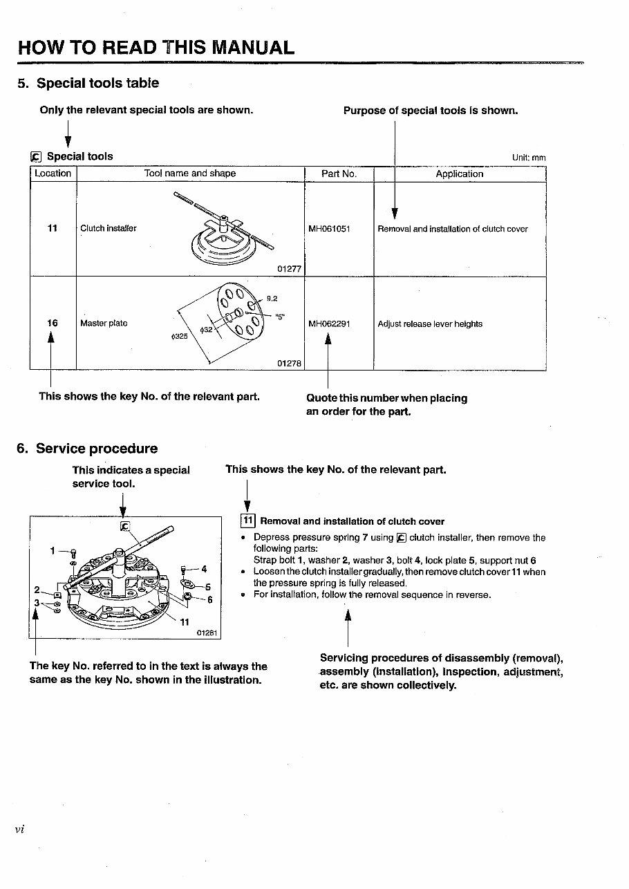
HOW TO READ THIS MANUAL 5. Special tools table Only the relevant special tools are shown. ~ [.g Special tools Location Tool name and shape 11 Clutch installer 01277 16 Master plate This shows the key No. of the relevant part. Purpose of special tools is shown. Unit:mm Part No. Application MH061051 Removal and installation of clutch cover MH062291 Adjust release lever heights Quote this number when placing an order for the part. 6. Service procedure vi This indicates a special service tool. This shows the key No. of the relevant part. + @] Removal and installation of clutch cover • Depress pressure spring 7 using [g clutch installer, then remove the following parts: · Strap bolt 1, washer 2, washer 3, bolt 4, lock plate 5, support nut 6 • Loosen the clutch installer gradually, then remove clutch cover11 when the pressure spring is fully released. • For installation, follow the removal sequence in reverse. The key No. referred to in the text is always the same as the key No. shown in the illustration. Servicing procedures of disassembly (removal), .assembly (installation), inspection, adjustment, etc. are shown collectively.
Terms and Units The terms and units in this manual are defined as follows. e This service manual contains important cautionary instructions and supplementary information under the following four .headings which identify the nature of the instructions and information: DANGER,&. WARNING_&.--- CAUTION,&. --- NOTE e Front and rear Precautions that should be taken in handling potentially dangerous substances such as battery fluid and coolant additives. Precautionary instructions, which, if not observed, could result in serious injury or death. Precautionary instructiqns, which, if not observed, could result in damage to or destruction of equipment or parts. Suggestions or supplementary information for more efficient use of equipment or a better understanding. The terms ''front" is the fan side and "rear'' the flywheels side of the engine. e Left and right The terms "right" and "left" shall be used to indicate the side as viewed from the flywheel side of the engine. e Terms of service standards (1) Standard value Standard value dimensions in designs indicating: the design dimensions. of individual parts, the standard clearC\nce between two parts when assembled, and the standard value for an assembly part, as the case may be. The figure in [ ] is the basic diameter. (2) Limit When the value of a part exceeds this, it is no longer serviceable in respect of performance and strength and must be replaced or repaired. e Tightening torque Excessive or insufficient tightening torque has particular importance in respect of performance. Accordingly, tightening torque is specified in locations that are to be tightened. Where there is no specified figure for tightening torque, follow the table covering standard tightening torques. When the item is to be tightened in a wet state, wet is indicated. Where there is no indication, read it as dry, and tighten at specified torque. vii
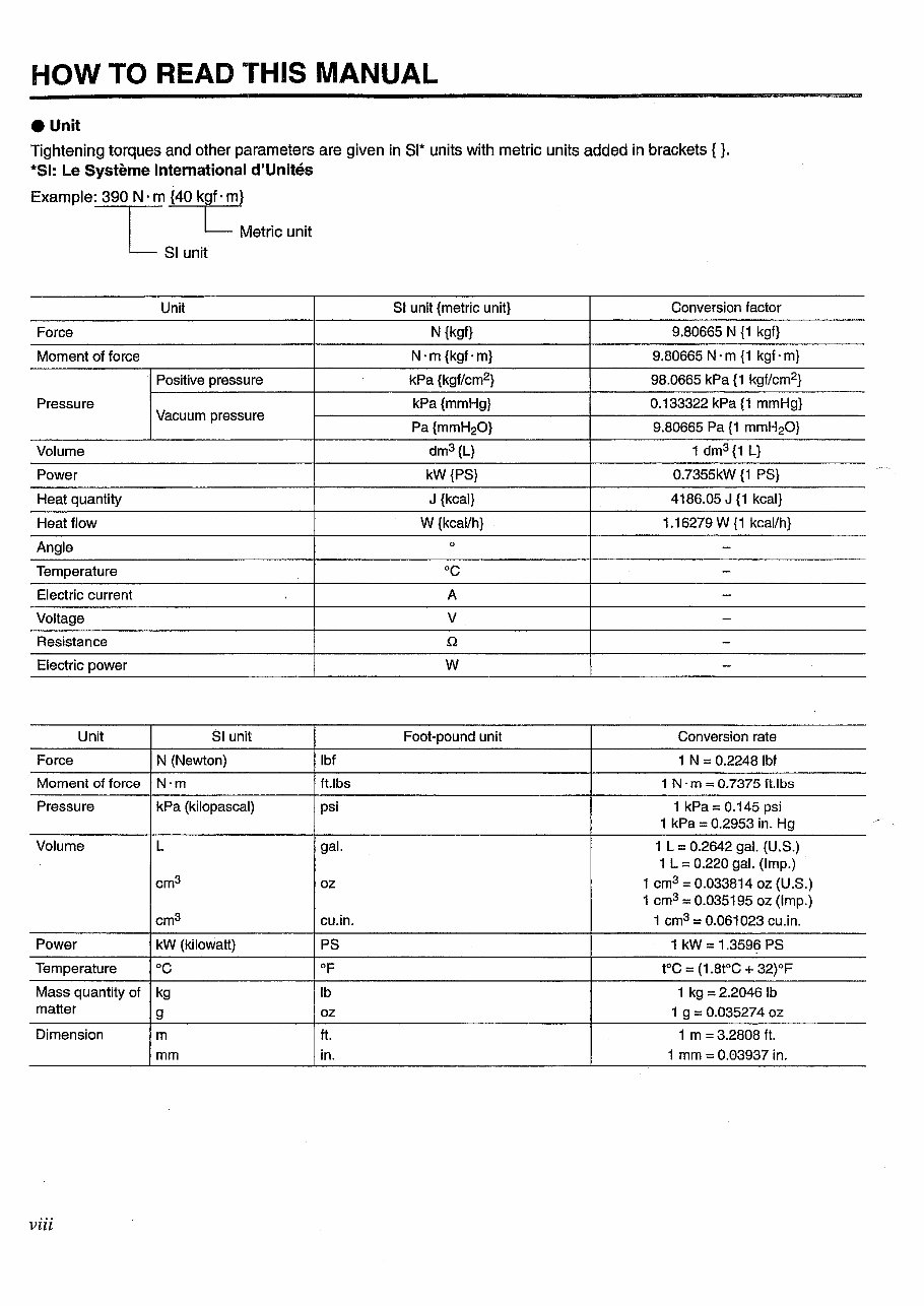
HOW TO READ THIS MANUAL eunit Tightening torques and other parameters are given in Sl* units with metric units added in brackets { }. *SI: Le Systeme International d'Unltes Example: 390 N · m {40 kgf · m} ~ L Metric unit L Sl unit Unit Force Moment of force Positive pressure Pressure Vacuum pressure Volume Power Heat quantity Heat flow Angle Temperature Electric current Voltage Resistance Electric power Unit Sl unit Force N (Newton) Moment of force N·m Pressure kPa (kilopascal) Volume L cm 3 cm 3 Power kW (kilowatt) Temperature oc Mass quantity of kg matter g Dimension m mm viii lbf ft.lbs psi gal. oz cu.in. PS OF lb oz ft. in. Sl unit {metric unit} Conversion factor N {kgf} 9.80665 N {1 kgf} N·m{kgf·m} 9.80665 N · m {1 kgf · m} kPa {kgf/cm2} 98.0665 kPa {1 kgf/cm2} kPa {mmHg} 0.133322 kPa {1 mmHg} Pa {mmH20l 9.80665 Pa {1 mmH20} dm3 {L} 1 dm 3 {1 L} kW {PS} 0.7355kW {1 PS} J {kcal} 4186.05 J {1 kcal} W {kcal/h} 1.16279W{1 kcal/h} 0 - oc - A - v - Q - w - Foot-pound unit Conversion rate 1 N = 0.2248 lbf 1 N · m = 0.7375 ft.lbs 1 kPa = 0.145 psi 1 kPa = 0.2953 in. Hg 1 L = 0.2642 gal. (U.S.) 1 L = 0.220 gal. (Imp.) 1 cm3 = 0.033814 oz (U.S.) 1 cm3 = 0.035195 oz (Imp.) 1 cm3 = 0.061023 cu. in. 1 kW = 1.3596 PS t°C = (1.8t°C + 32)°F 1 kg = 2.2046 lb 1 g = 0.035274 oz 1 m = 3.2808 ft. 1 mm = 0.03937 in.
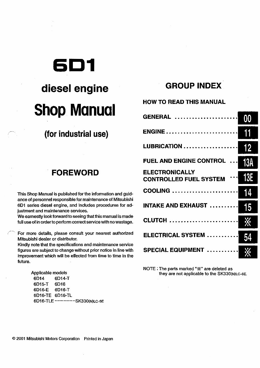
Mitsubishi 6D1 Diesel Engines (6D14/6D15/6D16) Service & Repair Manual is a comprehensive technical resource suitable for both professional mechanics and DIY enthusiasts.
Models covered:
6D14
6D14-T
6D15-T
6D16
6D16-E
6D16-T
6D16-TE
6D16-TLE
This manual includes detailed service, maintenance, troubleshooting, and replacement procedures for the engine. It features step-by-step instructions, clear images, and exploded-view illustrations, making it accessible for all users.
Please note:
This manual is not a generic repair guide but the official resource used by professional technicians. It encompasses all troubleshooting and replacement procedures provided by the manufacturer, with step-by-step instructions, exploded-view illustrations, and clear images.
It eliminates the need to search through numerous pages and offers the convenience of digital access, allowing users to search, bookmark, and even print specific sections.
Printable: Yes Language: English Compatibility: Compatible with various electronic devices, including PC, Mac, Android, and Apple devices. Requirements: Adobe Reader (free)
Recently Viewed
5,521,897Happy Clients
2,594,462eManuals
1,120,453Trusted Sellers
15Years in Business
Price:
Actual Price:
Mitsubishi 6D1 Diesel Engines (6D14/6D15/6D16) OEM Service & Repair Manual