Mitsubishi 4G3 Engine Factory Service Repair Manual
What's Included?
Lifetime Access
Fast Download Speeds
Online & Offline Access
Access PDF Contents & Bookmarks
Full Search Facility
Print one or all pages of your manual
BACKUP Service Manual ENGINE GROUP INDEX 1992 - 1993 Introduction . . . . . . . . . . . . . . . . . . . . . . . . . . . . FOREWORD The information contained in this service manual has been prepared for the professional automotive technician involved in daily repair operations. In- formation in this manual is divided into groups by engine models. Each group is further divided to address individual components within the group. These groups contain general information, specifica- tion, removal and installation, disassembly and reassembly procedures for the components. The first page of each group contains an alphabetical index to assist in finding the location of the component. The information, descriptions and spe- cifications were in effect at the time this manual was released. WE SUPPORT VOLUNTARY TECHNICIAN CERTIFICATION THROUGH National lnstit~te for AUTOMOTIVE SERVICE EXCELLENCE Engine 4G1 l . . . . . . . . . . . . . . . . . . . . . . . . . . . . . . . . . . . . . . . . mm 4G3 3 . . . . . . . . . . . . . . . , . . . . . . . . . . . . . . . . . . . . . . . . 4G6 <1992>> . . . . . . . . . . . . . . . . . . . . . . . . mm 4G9 9 . . . . . . . . . . . . . . . . . . . . . . . . . . . . . . . . . . ...*.. m 6G7 . . . . . . . . . . . . . . . . . . . . . . . . . . . . . . . . . . . . . . . . 4G6 <1993>> . . . . . . . . . . . . . . . . . . . . . . . . CCT Mitsubishi Motors Co[poration reserves the right to make changes in dew? or to make addltlons to or improvements in its products WIthout impoang any obligations upon itself to install them on its products previously manufactured. @ 1992 Mitsubishi Motors Corporation Printed in Japan
2 INTRODUCTION EXPLANATION OF MANUAL CONTENTS I Maintenance and Servicing Procedures (1) A diagram of the component parts is provided near the front of each section in order to give the reader a better under- standing of the installed condition of component parts. (2) The numbers provided within the diagram indicate the sequence for maintenance and servicing procedures; the symbol m indicates a non-reusable part; the tighten- ing torque is provided where applicable. 0 Removal steps: The part designation number corresponds to the number in the illustration to indicate removal steps. l Disassembly steps: The part designation number corresponds to the number in the illustration to indicate disassembly steps. 0 Installation steps: Specified in case installation is impossible in reverse order of removal steps. Omit- ted if installation is possible in reverse order of removal steps. l Reassembly steps: ia Specified in case reassembly is im$ossi- ble in reverse order of disassembly Omitted if reassembly is possible verse order of disassembly steps. Classification of Major Maintenance/ Service Points When there are major points relative to mainte- nance and servicing procedures (such as essential maintenance and service points, maintenance and service standard values, information regarding the use of special tools, etc.), these are arranged together as major maintenance and service points and explained in detail. GAO: Indicates that there are essential points for removal or disassembly. I)A4: Indicates that there are essential points for installation or reassembly. Symbols for Lubrication, Sealants and Adhesives Information concerning the locations for lubrica- tion and for application of sealants and adhesives is provided, by using symbols, in the diagram of component parts, or on the page following the component parts page, and explained. & . . Grease (multrpurpose grease unless there is a brand or type specified) . . . . . Sealant or adhesive i . . . . . Brake fluid, automatic transmission fllid or air conditioning compressor :m . . . . . Engine oil or gear oil I TSB Revision
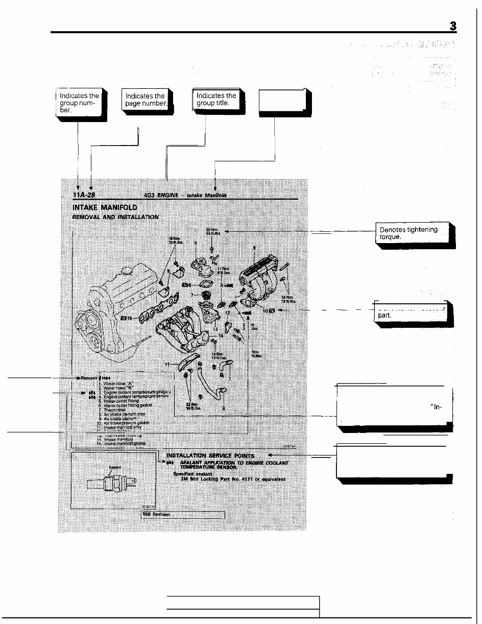
INTRODUCTION 3 Indicates the section title. Denotes non-reusable TSB Revision This number corresponds to the number appearing in “Removal steps”, “Disassembly steps”, “ln- stallation steps” or “Reassembly steps” I Operating procedures, cautions, etc. on removal, installation, dis- assembly and reassembly are de- scribed. I
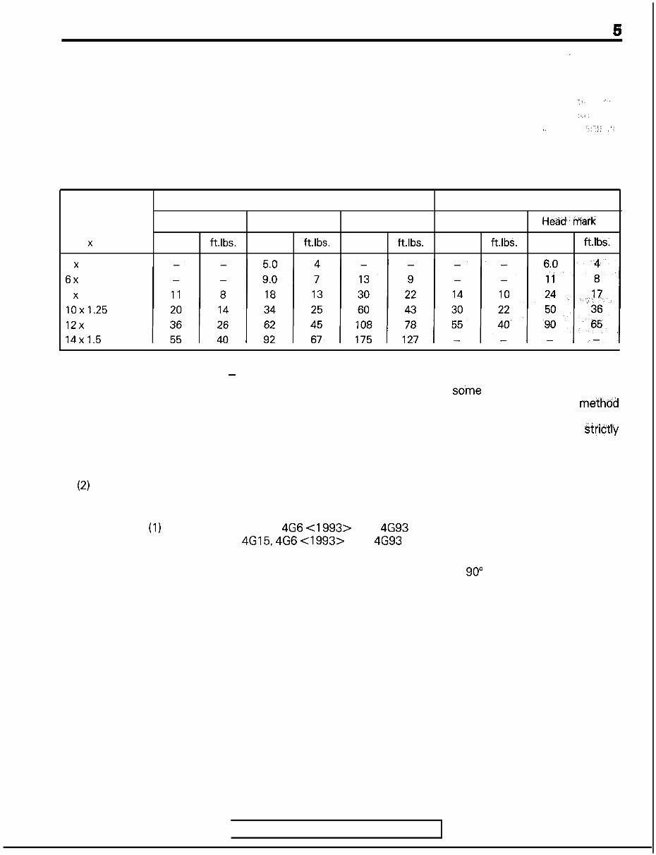
INTRODUCTION 6 SPECIAL TOOL NOTE . 1 Please refer to the special tool cross reference chart which is located in the service manual at the beginning of each group, for a cross reference from the MMC special tool number to the special tool number that is available in your market. iiS *‘l *.j, l” “...!: ‘/’ TORQUE REFERENCES General tightening torque is as shown in the following table. The specific part tightening torque is shown at the beginning of each group. Size mm (dia. x pitch) 5 x 0.8 6x 1.0 8 x 1.25 10x1.25 12x 1.25 14x1.5 Bolt with spring washer Flange bolt Head mark 4 Head mark 7 Head mark 10 Head mark 4 Heaid. i-MC 7 Nm ft.lbs. Nm ft.lbs. Nm ft.lbs. Nm ft.lbs. Nm ft.lbS. NEW TIGHTENING METHOD - BY USE OF BOLTS TO BE TIGHTENED IN PLASTIC AREA A new type of bolts, to be tightened in plastic area, is currently used in so’me parts of the engine. The tightening method for the bolts is different from the conventional one. Be sure to observe the method described in the text when tightening the bolts. Service limits are provided for the bolts. Make sure that the service limits described in the text are strictly observed. l Areas where the bolts are in use: (1) Cylinder head bolts (2) Main bearing cap bolts (3) Connecting rod cap bolts Remarks: The bolts in (1) and (2) apply to the 4G6 <I 993> and 4G93 engines. The bolts in (3) apply to the 4G15, 4G6 <1993> and 4693 engines. l Tightening Method After tightening the bolts to the specified torque, tighten them another 90” or 180” (twice 90”). The tightening method varies on different areas. Observe the tightening method described in the text. TSB Revision
INTRODUCTION FORM-IN-PLACE GASKET The engine has several areas where the form-in-place gasket (FIPG) is in use. To ensure that the gasket fully serves its purpose, it is necessary to observe some precautions when applying the gasket. Bead size, continuity and location are of paramount importance. Too thin a bead could cause leaks. Too thick a bead, on the other hand, could be squeezed out of location, causing blocking or narrowing of the fluid feed line. To eliminate the possibility of leaks from a joint, therefore, it is absolutely necessary to apply the gasket evenly without a break, while observing the correct bead size. The FIPG used in the engine is a room temperature vulcanization (Rn/) type and is supplied in a loo-gram tube (Part No. MD970389 or MD9971 10). Since the RTV hardens as it reacts with the moisture in the atmospheric air, it is normally used in the metallic flange areas. The FIPG, Part No. MD970389, can be used for sealing both engine oil and coolant, while Part No. 997110 can only be used for engine oil sealing. Disassembly The parts assembled with the FIPG can be easily disassembled without use of a special method. In some cases, however, the sealant between the joined surfaces may have to be broken bylightly striking with a mallet or similar tool. A flat gasket scraper may be lightly hammered in between the joined surfaces. In this case, however, care must be taken to prevent damage to the joined surfaces. Surface Preparation Thoroughly remove all substances deposited on the gasket application surfaces, using a gasket scraper or wire brush. Check to ensure that the surfaces to which the FIPG is to be applied is flat.‘ Make sure that there are no oils, greases and foreign substances deposited on the application surfaces. Do:not forget to remove the old sealant remaining in the bolt holes. Form-In-Place Gasket Application 5 When assembling parts with the FIPG, you must observe some precautions, but the procedure is very simple as in the case of a conventional precut gasket. Applied FIPG bead should be of the specified size and without breaks. Also be sure toencircle the bolt hole circumference with a completely continuous bead. The FIPG can be wiped away unless it is hardened. While the FIPG is still moist (in less than 15 minutes), mount the parts in position. When the parts are mounted, make sure that the gasket is applied to the required area only. The FIPG application procedure may vary on different areas. Observe the procedure described in the text when applying the FIPG. TSB Revision
4G15 BRACKET ................................................................ 53 CRANKSHAFT, FLYWHEEL AND DRIVE PLATE ........................................................ 51 CYLINDER HEAD AND VALVES ........................ 33 EXHAUST MANIFOLD AND WATER PUMP .................................................... 28 FRONT CASE AND OIL PUMP ............................ 39 FUEL AND EMISSION PARTS ............................ 22 GENERAL INFORMATION ................................ 2 GENERAL SPECIFICATIONS ............................ 5 GENERATOR AND IGNITION SYSTEM ........ 14 CONTENTS INTAKE MANIFOLD ............................................ 26 PISTON AND CONNECTING ROD .................... 43 ROCKER ARMS AND CAMSHAFT .................... 30 SEALANT ................................................................ 11 SERVICE SPECIFICATIONS ................................ 6 SPECIAL TOOLS .................................................... 12 THROlTLE BODY ................................................ 24 TIMING BELT ........................................................ 17 TORQUE SPECIFICATIONS ................................ 10
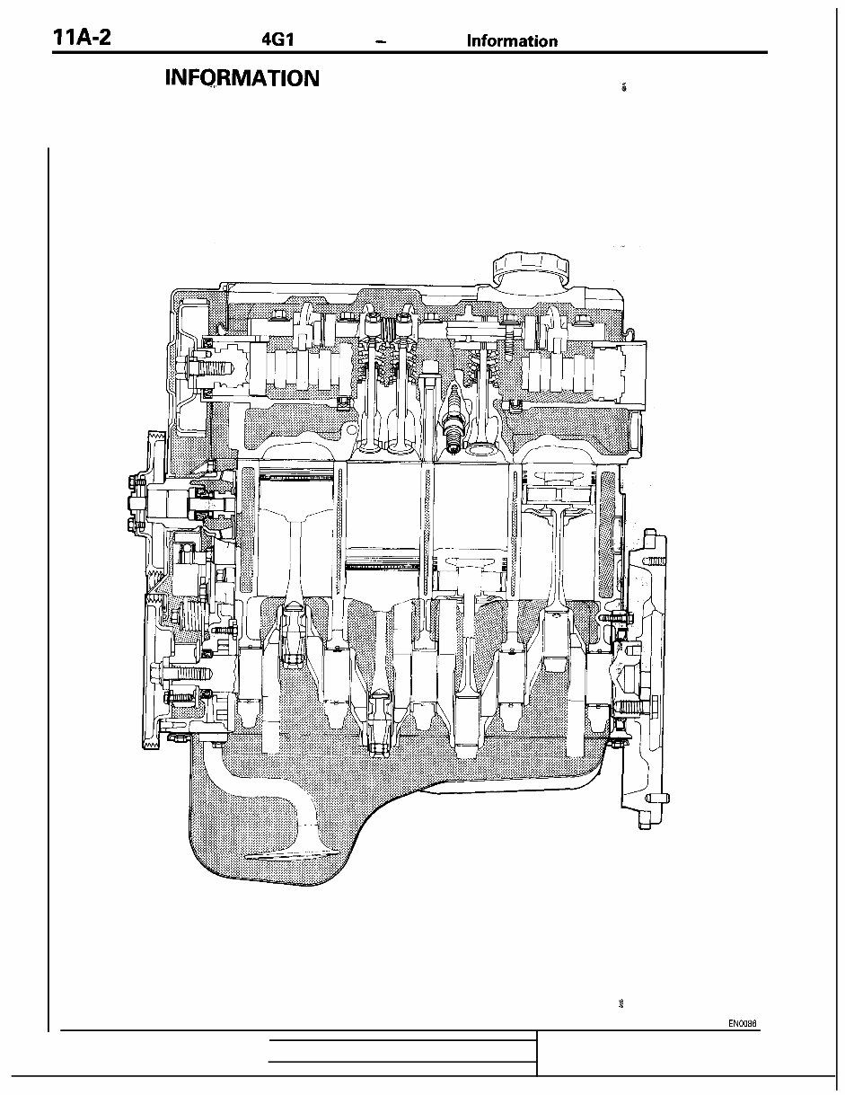
IlA-2 4Gl ENGINE - General Information GENERAL INFQRMATION ENGINE SECTIONAL VIEW TSB Revision 3 1 EN0086
This is the complete official full factory service repair manual for the Mitsubishi 4G3 Engine. It is a genuine repair service factory manual that covers all styles. This manual is useful for both professional mechanics and DIY enthusiasts.
The manual covers a wide range of topics including engine identification, general precautions, maintenance check list, special tools, troubleshooting, servicing specifications, tightening torques, disassembling and servicing, cooling system, fuel system, and electrical system.
It contains necessary illustrations, diagrams, and specifications to guide the mechanic through any repair procedure. Additionally, an advanced troubleshooting guide is included to help diagnose and correct any problem.
This highly detailed manual contains everything needed to repair, maintain, rebuild, refurbish, or restore the vehicle. All diagnostic and repair procedures are covered in great detail. It is designed to help users easily find the information they need and print out only the pages they require.
The manual is available in English and can be printed without any restriction. It is compatible with all PC-based Windows operating systems and Mac. The file format is either .OVA or .PDF, and it can be saved to the hard drive or burned to CD-ROM. All pages are printable, saving on shipping costs and waiting time for delivery.
With this manual, users can save on shop labor costs and perform all servicing themselves. It provides detailed substeps, notes, cautions, warnings, numbered instructions, bold figure numbers, detailed illustrations, and enlarged insets to help identify and examine parts in detail.
Furthermore, the manual makes it easy to diagnose and repair problems with the machine's electrical system, as troubleshooting and electrical service procedures are combined with detailed wiring diagrams for ease of use.
File Format: .OVA or .PDF
Language: English
Printable: Yes
Delivery: Link will appear on the checkout page after payment is complete
Requirements: Adobe Reader
Recently Viewed
5,521,897Happy Clients
2,594,462eManuals
1,120,453Trusted Sellers
15Years in Business
Price:
Actual Price:
Mitsubishi 4G3 Engine Factory Service Repair Manual