

1
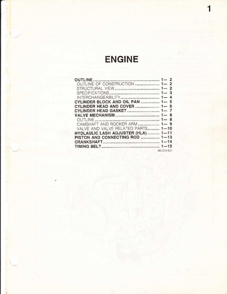
ENGINE
ouTLlNE ....',|- 2
OUTLINE OF CONSTRUCTION ... 1- 2
STRUCTURAL VIEW ... 1- 2
SPECIFICATIONS ....... 1- 3
INTERCHANGEABILITY............. .1- 4
CYLINDER BLOCK AND OIL PAN.............. 1- 5
CYLINDER HEAD AND COVER..........
CYLINDER HEAD GASKET 1_ 7
VALVE MECHAN|SM............ ...... 1- 8
OUTLINE
... 1: 8
CAMSHAFT AND ROCKER ARM........ 1- 9
VALVE AND VALVE RELATED PARTS......... 1_10
HYDLAULTC LASH ADJUSTER (HLA) 1-11
prsToN
AND CONNECTING ROD .............. 1-13
CRANKSHAFT.........
... 1-14
TIMING BELT 1-15
86U01 X-501
OUTLINE
OUTLINE OF CONSTRUCTION
The New 626 is equipped with an F2 2.2liter engine. This engine is based on the previous 626 FE
engine, with increased displacement. The engine features three valves per cylinder and a new timing
belt layout.
Main Changes:
.1.
The piston stroke is increased for greater displacement
2, Intake and exhaust efficiency is improved through the use of two smaller rntake valves and one
larger exhaust valve per cylinder, for an increase of total valve area.
3. The timing belt layout is changed for improved durability and noise reduction.
4. A stiffener is used between the cylinder block and the oil pan to lessen noise and improve performance.
R Tha nrrlinrlor hlnnft gpf
crankshaft strength is improved to meet the higher power output.
6. Hydraulic lash adjusters are used to reduce noise, thus the valve clearance is made maintenance-free.
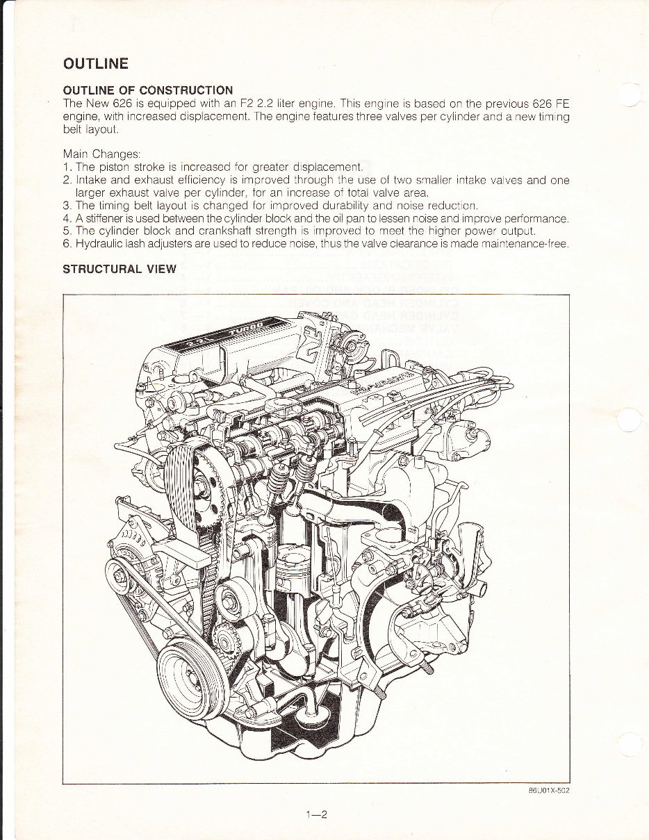
STRUCTURAL VIEW
86U01 X-502
t-z
SPECIFICATIONS
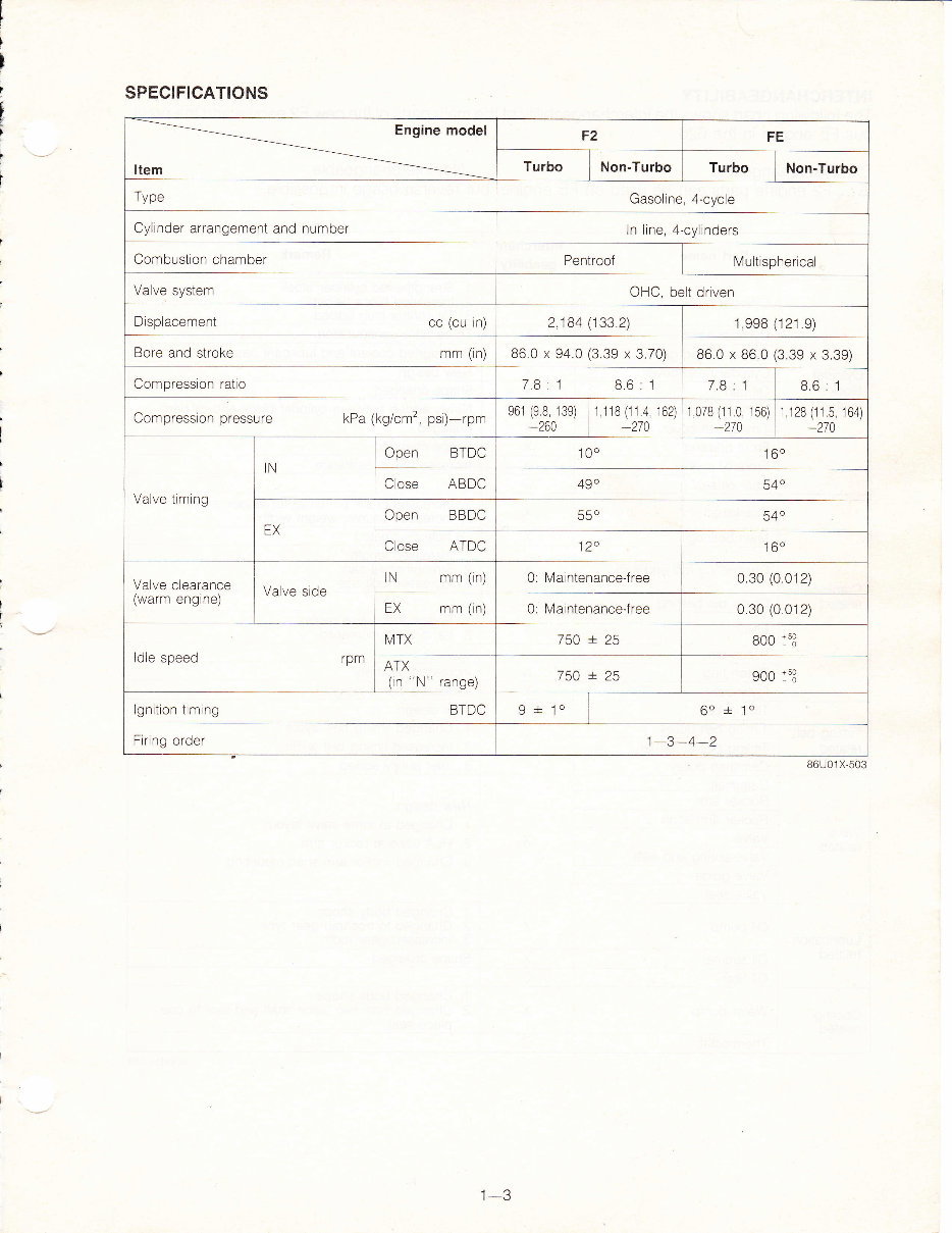
F2 FE
Turbo Non-Turbo Turbo Non-Turbo
Trrno
' J Y" Gasoline, 4-cycle
Cylinder arrangement and number ln line, 4-cylinders
Combustion chamber Pentroof Multispherical
Valve system
OHC, belt driven
Displacement cc (cu in) 2,184 (133.2) 1,998 (121 .9)
Bore and stroke mm (in) 86.0 x 94.0 (3.39 x 3.70) 86.0 x 86.0 (3.39 x 3.39)
Compression ratio 7.8:1 8.6:1 7.8:1 8.6:1
Compression pressure kPa (kg/cm', psi)-rpm
e61 (98 139)
*260
1 118 (11 4 162)
_270
1 078 (11 0 156)
_270
1 128 (11.5 164)
-270
Valve timing
IN
Open BTDC 100 160
Close ABDC 49"
tr/1o
EX
Open BBDC 550
Close ATDC 120
-160
\/-t,,^
^t^^,^^^^ v otv9 utv4t 4t tuE
(warm engine)
Valve side
IN mm (in) 0: Maintenancejree 0.30 (0 012)
EX mm (in) 0: Maintenance-free 0.30 (0 012)
ldle speed rpm
N/TX 750 + 25 8oo i53
ATX
(in "N"
range)
7qi + )q
9oo 153
lgnition timing BTDC
o -t- lo
6o
+
1o
Firing order 1-3-4-2
86U01 X-503
t-J
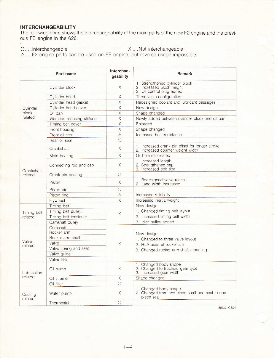
INTERCHANGEABILITY
The following chart shows the interchangeability of the main parts of the new F2 engine and the previ-
ous FE engine in the 626.
C.....lnterchangeable X..... Not interchangeable
L.....F2 engine parts can be used on FE engrne, but reverse usage impossible.
Part name
Interchan-
geability
Remark
Cylinder
block
related
Cylinder block X
1
2.
3.
Strengthened cylinder block
Increased block height
Oil control plug added
Cvlinder head Three-valve confiouration
Cylinder head gasket X Redesiqned coolant and lubricant
passaoes
Cvlinder head cover X New desion
Oil pan X Shape chanqed
Vibration reducino stiffener X Newlv added between cvlinder block and oil
pan
Timinq belt cover X Enlaroed
Front housino X Shape changed
Front oil seal A Increased heat-resistance
Rear oil seal C
Crankshaft
rol2ia.i
Crankshaft
1.
2.
Increased crank pin offset for longer stroke
Increased counter weicht width
Main bearing Oil hole elliminated
Connecting rod and cap X
1.
2.
3.
Increased length
Strengthened cap
Increased bolt size
Crank
pin
bearinq o
Piston X
1,
2.
Redesigned valve recess
Land width increased
Piston pin C
Piston rino A Increased reliabilitv
F vwneel
Increased rnertia weioht
Timing belt
.^l^+^l
IEI4LgU
T mino belt
X
New design
1. Changed trm ng belt layoul
2. Increased timing belt width
Q lrllor nr rllarr lrirlod
vv,,v
y qvvvv
Timinq belt
pullev
mino belt tensioner
Camshaft
pullev
Valve
related
iamshaft
New design
1. Changed to three valve layout
2 HLA used at rocker arm
3. Changed rocker arm shaft mounting
Rocker arm
Rocker arm shafl
Valve
Valve sorino and seat
Valve
quide
Valve seal
Lubrication
.^l^+^A
I claLgu
Oil pump X
1. Changed body shope
2. Changed to trochoid gear type
3. lncreased oear width
Oil strainer X Shape changed
Oil filter C
Cooling
related
Water pump X
1. Changed body shape
2. Changed from two piece shaft and seal to one
olece seal
Thermostat o
86U01 X-504
1A
t-?
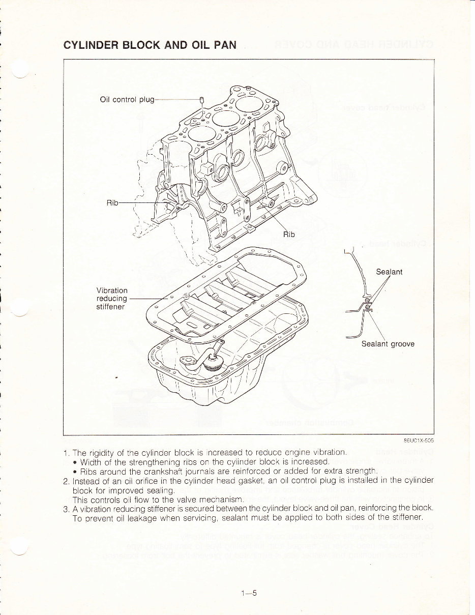
CYLINDER BLOCK AND OIL PAN
86U01 X-505
'1.
The rigidity of the cylinder block is increased to reduce engine vibration.
o
Width of the strengthening ribs on the cylinder block is increased.
.
Ribs around the crankshaft
journals
are rernforced or added for extra strength.
2. Instead of an oil orifrce in the cylinder head gasket, an oil control plug is installed in the cylinder
block for improved sealing,
This controls oil flow to the valve mechanlsm.
3. A vibration reducrng stiffener is secured between the cylinder block and oil pan, reinforcing the block.
To prevent oil leakage when servicing, sealant must be applied to both sides of the stiffener.
\
\\ Seal
V
E/
"/R
J\
Sealant
ant
Vibration
reducing
stiffener
wt
I-U
You're Reading a Preview
What's Included?
 Lifetime Access
Fast Download Speeds
Offline Viewing
Access Contents & Bookmarks
Full Search Facility
Print one or all pages of your manual
$39.99
Mazda engine service manual F2-2
Viewed 50 Times Today

What's Included?
Lifetime Access
Fast Download Speeds
Offline Viewing
Access Contents & Bookmarks
Full Search Facility
Print one or all pages of your manual
$39.99


Secure transaction
What's Included?
Lifetime Access
Fast Download Speeds
Offline Viewing
Access Contents & Bookmarks
Full Search Facility
Print one or all pages of your manual
Description
Get the service manual for F2-2.0G and F2-2.2G models. This manual covers 2.0 LPG (2-3[t]), 2.2 LPG (2-3[t]), 2.0 LPG (1-2[t]), 2.0 Gas (2-3[t]), and 2.2 Gas (2-3[t]), as well as 2.0 Gas (1-2[t]). It's a valuable resource for both professional mechanics and DIY enthusiasts.


