

1
COMPILER TECO/ATI ENDORSED DATE
29.02.2004
REG. CODE
1-5302-633
MODEL N°
51074
DATE OF ISSUE
02-04
REVISION 00
RY125
1
st
Edition
WORK SHOP
MANUAL
RY 125 series engines, p.no. 1-5302-633
2
COMPILER TECO/ATI ENDORSED DATE
29.02.2004
REG. CODE
1-5302-633
MODEL N°
51074
DATE OF ISSUE
02-04
REVISION 00
FOREWORD
We have done all in our power to give up to date and accurate technical information in this manual. Ruggerini engines
are, however, constantly developing thus the data in this publication may be liable to modification without prior notice.
The information in this manual is the exclusive property of Ruggerini. Neither partial nor total duplications or reprints
are therefore permitted without the express authorization of Ruggerini.
The information in this manual is given on the assumption that:
1 - The persons who service Ruggerini engines have been adequately trained and outfitted to safely and professionally
carry out the necessary tasks;
2 - The persons who service Ruggerini engines possess the necessary skills and special Ruggerini tools to safely
and professionally carry out the necessary tasks;
3 - The persons who service Ruggerini engines have read the specific information concerning the above mentioned
Service operations and that they have clearly understood the operations required.
GENERAL SERVICE NOTES
1 - Only use genuine Ruggerini spare parts. Use of spurious spares may lead to incorrect performance and shorten
the life of the engines.
2 - The metric system is used to express all data, i.e. the dimensions are given in millimeters (mm), torque is
expressed in Newton-meters (Nm), weight in kilograms (kg), volume in liters or cubic centimeters (cc) and
pressure in barometric units (bar).
3
COMPILER TECO/ATI ENDORSED DATE
29.02.2004
REG. CODE
1-5302-633
MODEL N°
51074
DATE OF ISSUE
02-04
REVISION 00
WARRANTY CERTIFICATE
WARRANTY CERTIFICATE
Products Ruggerini Motori manufactured by Lombardini Srl are warranted to be free from non-conformity defects for a
period of 24 months from the date of delivery to the first end user.
For engines fitted to stationary equipment, working at constant load and at constant and/or slightly variable speed
within the setting limits, the warranty covers a period up to a limit of 2000 working hours, if the above mentioned
period (24 months) is not expired.
If no hour-meter is fitted, 12 working hours per calendar day will be considered.
For what concerns the parts subject to wear and deterioration (injection/feeding system, electrical system, cooling
system, sealing parts, non-metallic pipes, belts) warranty covers a maximum limit of 2000 working hours, if the above-
mentioned period (24 months) is not expired.
For correct maintenance and replacement of these parts, it is necessary to follow the instructions reported in the
documentation supplied with each engine.
To ensure the engine warranty is valid, the engine installation, considering the product technical features, must be
carried out by qualified personnel only.
The list of the Lombardini authorized dealers for Ruggerini Motori products is reported in the “World Service
Organisation” booklet, supplied with each engine.
Special applications involving considerable modifications to the cooling/lubricating system (for ex.: dry oil sump),
filtering system, turbo-charged models, will require special written warranty agreements.
Within the above stated periods Lombardini Srl directly or through the Ruggerini Motori authorized network will repair
and/or replace free of charge any own part or component that, upon examination by Ruggerini Motori Service Dept. or
by an authorized Ruggerini Motori agent, is found to be defective in conformity, workmanship or materials.
Any other responsibility/obligation for different expenses, damages and direct/indirect losses deriving from the engine
use or from both the total or partial impossibility of use, is excluded.
The repair or replacement of any component will not extend or renew the warranty period.
Lombardini Srl warranty obligations here above described will be cancelled if:
- Engines are not correctly installed and as a consequence the correct functional parameters are not respected and
altered.
- Engines are not used according to the instructions reported in the “Use and Maintenance” booklet supplied with
each engine.
- Any seal affixed to the engine by the Manufacturer has been tampered with or removed.
- Spare parts used are not original from Manufacturer.
- Feeding and injection systems are damaged by unauthorized or poor quality fuel types.
- Electrical system failure is due to components, connected to this system, which are not supplied or installed by
the Manufacturer.
- Engines have been disassembled, repaired or altered by any part other than an authorized Ruggerini Motori agent.
Following expiration of the above stated warranty periods and working hours, Lombardini will have no further
responsibility for warranty and will consider its here above mentioned obligations for warranty complete.
Any warranty request related to non-conformity of the product must be addressed to the Ruggerini Motori service
agents.
4
COMPILER TECO/ATI ENDORSED DATE
29.02.2004
REG. CODE
1-5302-633
MODEL N°
51074
DATE OF ISSUE
02-04
REVISION 00
INDEX
I TROUBLE SHOOTING__________________________________________________________ Page 7
II SAFETY AND WARNING DECALS - SAFETY INSTRUCTIONS ____________________________ " 8
III MODEL NUMBER AND IDENTIFICATION _____________________________________________ " 10
IV TECHNICAL DATA ______________________________________________________________" 11
V CHARACTERISTICS _____________________________________________________________ " 12
VI OVERALL DIMENSIONS __________________________________________________________ " 13
VII SPECIAL TOOLS________________________________________________________________ " 14
VIII MAINTENANCE - RECOMMENDED OIL TYPE - REFILLING _______________________________ " 15
IX DISASSEMBLY OF THE ENGINE _________________________________________________ Page 17
Demounting and remounting the main bearings .......................................................................................................... 18
Demounting the piston ................................................................................................................................................... 18
Flywheel extraction .......................................................................................................................................................... 17
Removing the cover on the timing system side ............................................................................................................. 17
Removing the injection pump ......................................................................................................................................... 17
Removing the injector ..................................................................................................................................................... 17
X CHECKS AND OVERHAUL ______________________________________________________ Page 19
Camshaft ........................................................................................................................................................................ 23
Checking the oil pump .................................................................................................................................................... 23
Connecting rod ............................................................................................................................................................... 21
Crankshaft ....................................................................................................................................................................... 22
Cylinder ........................................................................................................................................................................... 20
Fuel pump (optional) ...................................................................................................................................................... 24
Head ................................................................................................................................................................................ 19
Injection pump tappets and pads ................................................................................................................................... 24
Lubrication circuit ............................................................................................................................................................ 22
Oil retention rings ............................................................................................................................................................ 22
Piston rings - Piston - Pin ............................................................................................................................................... 21
Rocker arms ................................................................................................................................................................... 20
Tapets and rocker arms .................................................................................................................................................. 24
Valve springs ................................................................................................................................................................... 20
Valves - Guides - Housings ............................................................................................................................................ 19
This manual contains pertinent information regarding the repair of RUGGERINI air-cooled, indirect injection Diesel engines
type RY125: updated February 29, 2004.
5
COMPILER TECO/ATI ENDORSED DATE
29.02.2004
REG. CODE
1-5302-633
MODEL N°
51074
DATE OF ISSUE
02-04
REVISION 00
INDEX
XI INJECTION EQUIPMENT ________________________________________________________ Page 25
Checking the injection pump .......................................................................................................................................... 26
Demounting and remounting ......................................................................................................................................... 28
Fuel circuit ....................................................................................................................................................................... 25
Injection pump ................................................................................................................................................................ 25
Injection pump assembly ............................................................................................................................................... 26
Injection pump calibration .............................................................................................................................................. 26
Injector ............................................................................................................................................................................. 27
Injector inspection and calibration ................................................................................................................................. 27
Leak test .......................................................................................................................................................................... 27
XII ELECTRICAL EQUIPMENT ______________________________________________________ Page 29
Characteristics of the system ......................................................................................................................................... 29
Checking the alternator ................................................................................................................................................... 30
Checking the system ...................................................................................................................................................... 29
Ring gear ........................................................................................................................................................................ 30
XIII ENGINE ASSEMBLY ___________________________________________________________ Page 31
Camshaft ........................................................................................................................................................................ 34
Connecting rod - drive shaft connection ......................................................................................................................... 33
Counter-shaft .................................................................................................................................................................. 33
Cover on timing system side .......................................................................................................................................... 35
Cylinder ........................................................................................................................................................................... 36
Drive shaft assembly ...................................................................................................................................................... 33
Flywheel .......................................................................................................................................................................... 35
Head ................................................................................................................................................................................ 36
Injection lead ................................................................................................................................................................... 37
Injection pump tappets ................................................................................................................................................... 31
Injector and injector tube ................................................................................................................................................ 38
Mounting the injection pump on the engine ................................................................................................................... 38
Oil retention rings ............................................................................................................................................................ 35
Piston .............................................................................................................................................................................. 36
Play adjustment .............................................................................................................................................................. 34
Preparing the engine block ............................................................................................................................................. 31
Removal and assembly of the drive shaft gear .............................................................................................................. 33
Timing system cover pre-assembly ............................................................................................................................... 32
Valve clearance ............................................................................................................................................................... 37
6
COMPILER TECO/ATI ENDORSED DATE
29.02.2004
REG. CODE
1-5302-633
MODEL N°
51074
DATE OF ISSUE
02-04
REVISION 00
INDEX
XIV ENGINE TESTING _____________________________________________________________ Page 39
Braked engine test .......................................................................................................................................................... 39
Rpm regulation ............................................................................................................................................................... 39
XV STORAGE ___________________________________________________________________ Page 40
Setting at work ................................................................................................................................................................. 40
Storage for up to 6 months ............................................................................................................................................. 40
Storage periods of more than 6 months ........................................................................................................................ 40
XVI QUICK REFERENCE CHARTS ____________________________________________________ Page 41
Adjustments .................................................................................................................................................................... 41
Couplings ........................................................................................................................................................................ 41
Standard screw tightening torques ................................................................................................................................. 42
Tightening torques .......................................................................................................................................................... 42
XVII SERVICE ____________________________________________________________________ Page 43
7
COMPILER TECO/ATI ENDORSED DATE
29.02.2004
REG. CODE
1-5302-633
MODEL N°
51074
DATE OF ISSUE
02-04
REVISION 00
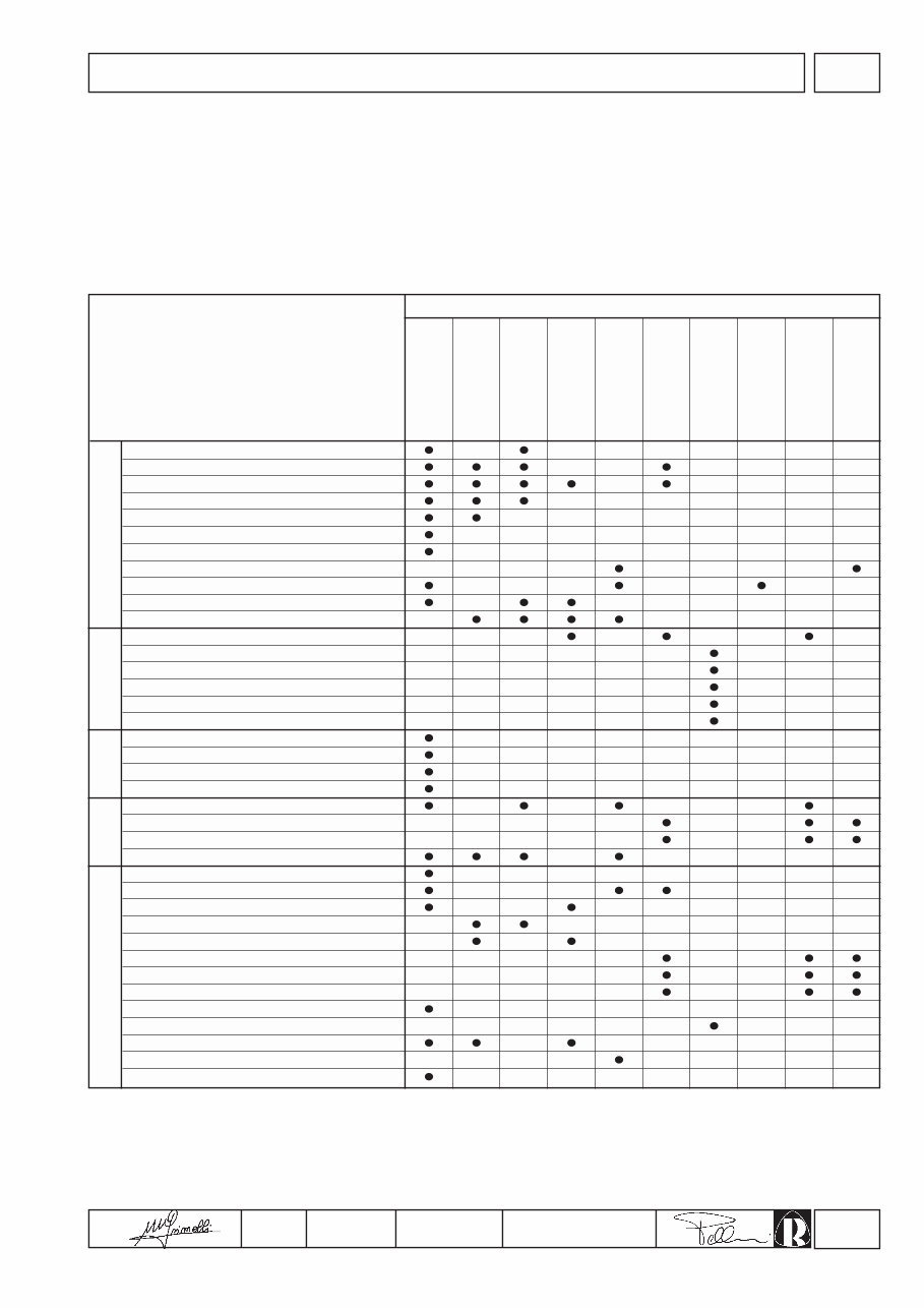
I TROUBLE SHOOTING
Clogged pipes
Clogged fuel filter
Air inside fuel circuit
Clogged tank breather hole
Faulty fuel pump
Injector jammed
Jammed injection pump delivery valve
Wrong injector setting
Excessive plunger blow-by
Jammed injection pump delivery control
Wrong injection pump setting
Oil level too high
Jammed pressure relief valve
Worn oil pump
Air inside oil suction pipe
Faulty pressure gauge or switch
Clogged oil suction pipe
Battery discharged
Wrong or inefficient cable connection
Defective ignition switch
Defective starter motor
Clogged air filter
Excessive idle operation
Incomplete running-in
Engine overloaded
Advanced injection
Delayed injection
Incorrect governor linkage adjustment
Broken or loose governor spring
Idle speed too low
Worn or jammed piston rings
Worn or scored cylinders
Worn valve guides
Jammed valves
Worn bearings
Governor linkage not free to slide
Drive shaft not free to slide
Damaged cylinder head gasket
TROUBLE
LUBRICATION
POSSIBLE CAUSE
FUEL CIRCUIT
ELECTRIC
SYSTEM
MAINTE-
NANCE
SETTINGS/REPAIRS
POSSIBLE CAUSES AND TROUBLE SHOOTING
The following table contains the possible causes of some failures which may occur during operation. Always perform these
simple checks before removing or replacing any part.
Engine does not
start
No acceleration
Black smoke
Excessive oil
consumption
Too low oil
pressure
Engine starts but
stops
Non-uniform speed
White smoke
Oil and fuel
dripping from
exhaust
Increase oil level
8
COMPILER TECO/ATI ENDORSED DATE
29.02.2004
REG. CODE
1-5302-633
MODEL N°
51074
DATE OF ISSUE
02-04
REVISION 00
II SAFETY AND WARNING DECALS - SAFETY INSTRUCTIONS
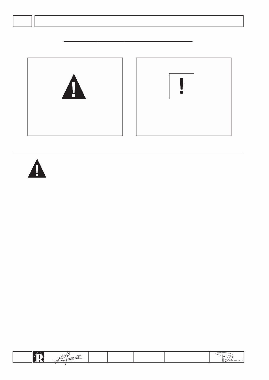
Failure to comply with the
instructions could result in
damage to persons and
property
Failure to comply with the
instructions could lead to
technical damage to the
machine and/or system
SAFETY AND W ARNING DECALS
SAFETY INSTRUCTIONS
DANGER CAUTION
• Ruggerini Engines are built to supply their performances in a safe and long-lasting way. To obtain these results, it is
essential for users to comply with the servicing instructions given in the relative manual along with the safety
recommendations listed below.
• The engine has been made according to a machine manufacturer's specifications and all actions required to meet the
essential safety and health safeguarding requisites have been taken, as prescribed by the current laws in merit. All
uses of the engine beyond those specifically established cannot therefore be considered as conforming to the use
defined by Ruggerini which thus declines all liability for any accidents deriving from such operations.
• The following indications are dedicated to the user of the machine in order to reduce or eliminate risks concerning engine
operation in particular, along with the relative routine maintenance work.
• The user must read these instructions carefully and become familiar with the operations described. Failure to do this
could lead to serious danger for his personal safety and health and that of any persons who may be in the vicinity of
the machine.
• The engine may only be used or assembled on a machine by technicians who are adequately trained about its operation
and the deriving dangers. This condition is also essential when it comes to routine and, above all, extraordinary
maintenance operations which, in the latter case, must only be carried out by persons specifically trained by Ruggerini
and who work in compliance with the existing documentation.
• Variations to the functional parameters of the engine, adjustments to the fuel flow rate and rotation speed, removal of
seals, demounting and refitting of parts not described in the operation and maintenance manual by unauthorized
personnel shall relieve Ruggerini from all and every liability for deriving accidents or for failure to comply with the laws
in merit.
• On starting, make sure that the engine is as horizontal as possible, unless the machine specifications differ. In the
case of manual start-ups, make sure that the relative actions can take place without the risk of hitting walls or dangerous
objects, also considering the movements made by the operator. Pull-starting with a free cord (thus excluding self-
winding starting only), is not permitted even in an emergency.
• Make sure that the machine is stable to prevent the risk of overturning.
• Become familiar with how to adjust the rotation speed and stop the engine.
• Never start the engine in a closed place or where there is insufficient ventilation. Combustion creates carbon monoxide,
an odourless and highly poisonous gas. Lengthy stays in places where the engine freely exhausts this gas can lead
to unconsciousness and death.
9
COMPILER TECO/ATI ENDORSED DATE
29.02.2004
REG. CODE
1-5302-633
MODEL N°
51074
DATE OF ISSUE
02-04
REVISION 00
II SAFETY AND WARNING DECALS - SAFETY INSTRUCTIONS
• The engine must not operate in places containing inflammable materials, in explosive atmospheres, where there is dust
that can easily catch fire unles specific, adequate and clearly indicated precautions have been taken and have been
certified for the machine.
• To prevent fire hazards, always keep the machine at least one meter from buildings or from other machinery.
• Children and animals must be kept at a due distance from operating machines in order to prevent hazards deriving
from their operation.
• Fuel is inflammable. The tank must only be filled when the engine is off. Thoroughly dry any spilt fuel and move the
fuel container away along with any rags soaked in fuel or oil. Make sure that no soundproofing panels made of
porous material are soaked in fuel or oil. Make sure that the ground or floor on which the machine is standing has
not soaked up any fuel or oil.
• Fully tighten the tank plug each time after refuelling. Do not fill the tank right to the top but leave an adequate space
for the fuel to expand.
• Fuel vapour is highly toxic. Only refuel outdoors or in a well ventilated place.
• Do not smoke or use naked flames when refuelling.
• The engine must be started in compliance with the specific instructions in the operation manual of the engine and/or
machine itself. Do not use auxiliary starting aids that were not installed on the original machine (e.g. Startpilot’).
• Before starting, remove any tools that were used to service the engine and/or machine. Make sure that all guards
have been refitted.
• During operation, the surface of the engine can become dangerously hot. Avoid touching the exhaust system in
particular.
• Before proceeding with any operation on the engine, stop it and allow it to cool. Never carry out any operation whilst
the engine is running.
• The coolant fluid circuit is under pressure. Never carry out any inspections until the engine has cooled and even in
this case, only open the radiator plug or expansion chamber with the utmost caution, wearing protective garments
and goggles. If there is an electric fan, do not approach the engine whilst it is still hot as the fan could also start
operating when the engine is at a standstill. Only clean the coolant system when the engine is at a standstill.
• When cleaning the oil-cooled air filter, make sure that the old oil is disposed of in the correct way in order to
safeguard the environment. The spongy filtering material in oil-cooled air filters must not be soaked in oil. The
reservoir of the separator pre-filter must not be filled with oil.
• The oil must be drained whilst the engine is hot (oil T ~ 80°C). Particular care is required to prevent burns. Do not
allow the oil to come into contact with the skin.
• Make sure that the drained oil, the oil filter and the oil it contains are disposed of in the correct way in order to
safeguard the environment.
• Pay attention to the temperature of the oil filter when the filter itself is replaced.
• Only check, top up and change the coolant fluid when the engine is off and cold. Take care to prevent fluids
containing nitrites from being mixed with others that do not contain these substances since "Nitrosamine",
dangerous for the health, can form. The coolant fluid is polluting and must therefore be disposed of in the correct
way to safeguard the environment.
• During operations that involve access to moving parts of the engine and/or removal of rotating guards, disconnect
and insulate the positive wire of the battery to prevent accidental short-circuits and to stop the starter motor from
being energized.
• Only check belt tension when the engine is off.
• Only use the eyebolts installed by Ruggerini to move the engine. These lifting points are not suitable for the entire
machine; in this case, the eyebolts installed by the manufacturer should be used.
10
COMPILER TECO/ATI ENDORSED DATE
29.02.2004
REG. CODE
1-5302-633
MODEL N°
51074
DATE OF ISSUE
02-04
REVISION 00
III MODEL NUMBER AND IDENTIFICATION
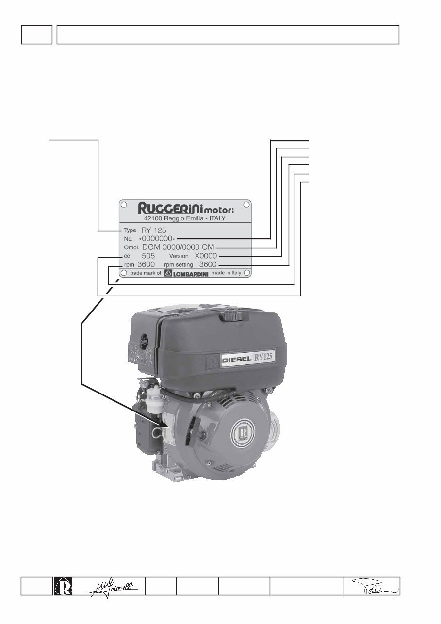
ENGINE IDENTIFICATION
Engine Serial Number
Approval code
Customer's code
R.P.M. setting
R.P.M.
Displacement (cc)
MODEL NUMBER
Model
You're Reading a Preview
What's Included?
 Lifetime Access
Fast Download Speeds
Online & Offline Access
Access PDF Contents & Bookmarks
Full Search Facility
Print one or all pages of your manual
$26.99
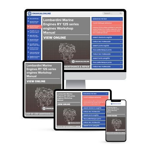
Lombardini Marine Engines RY 125 series engines Workshop Manual
Viewed 84 Times Today

What's Included?
Lifetime Access
Fast Download Speeds
Online & Offline Access
Access PDF Contents & Bookmarks
Full Search Facility
Print one or all pages of your manual
$26.99

Secure transaction
What's Included?
Lifetime Access
Fast Download Speeds
Online & Offline Access
Access PDF Contents & Bookmarks
Full Search Facility
Print one or all pages of your manual
Description
- This Workshop Manual covers all the models listed below:
- RY 125
- RY 125 BS
- RY 125 BS CSA
- RY 125/S
- RY 125/S CSA
This workshop manual is essential for servicing, maintaining, and repairing any of the Lombardini Marine RY 125 series engines. It includes clear and detailed instructions, photos, illustrations, and diagrams to assist you. The manual covers technical information such as engine torque settings, piston and ring specifications, special tools, and more. It is a valuable resource for professional mechanics and DIY enthusiasts who want to repair, service, or maintain their Lombardini Marine RY 125 series engine. The manual is available in digital format for instant download.


