- 2 - Service Manual LW 502 automotive _ cod. 1.5302.727 - 2° ed_rev. 01 ATLO REGISTERING DOCUMENT MODIFICATIONS This document is made up of 98 pages (-sides - excluding the cover and title page). Pages are numbered in progressive order from 051135.01 to 051135.98. Any modifications to this document must be registered by the drafting body and approved by the head of the Quality Management System, with completion of the table below. Copyright 2005 - Lombardini. Reproduction, even partial, of this document is subject to the manufacturer’s written authorisation. The manufacturer is committed to a policy of continuing improvement and reserves the right to modify the document, with no obligation to notify, providing that omission to do so constitutes no safety risk. The text may be reproduced in part or in whole, providing that the author is cited. Text and graphics by: IDM Esperti in Comunicazione Tecnica - Forlì Drafting body Document Code Edition Issue date Review date Replaced Pages Added Pages Eliminated pages 1-5302-727 2° 30/06/05 10/01/2007
- 3 - Service Manual LDW 502 automotive _ cod. 1.5302.727 - 2° ed_rev. 01 1 GENERAL REMARKS AND SAFETY 1.1 PURPOSE OF THE MANUAL ..................................... 5 1.2 USING THIS MANUAL ................................................ 5 1.3 MANUFACTURER AND ENGINE IDENTIFICATION .. 5 1.4 GLOSSARY AND TERMINOLOGY ............................. 6 1.5 WARRANTY CLAUSES .............................................. 6 1.6 GENERAL SAFETY REGULATIONS .......................... 6 1.7 GENERAL SAFETY DURING OPERATING PHASES 6 1.8 SAFETY AND ENVIRONMENTAL IMPACT ................ 7 1.9 PRECAUTIONS WHEN THE ENGINE IS INSTALLED ON THE MACHINE ..................................................... 7 1.10 PRECAUTIONS WHEN THE ENGINE IS ON THE ROTATING STAND ..................................................... 7 2 TECHNICAL INFORMATION 2.1 GENERAL DESCRIPTION OF THE ENGINE ............. 9 2.2 TECHNICAL SPECIFICATIONS ................................ 10 2.3 CHARACTERISTIC CURVE DIAGRAMS ................. 12 2.4 ALTERNATOR LOAD CURVE DIAGRAMS .............. 13 2.5 LUBRICANTS ........................................................... 14 2.5.1 SAE Classification ..................................................... 14 2.5.2 API/MIL sequences ................................................... 14 2.5.3 ACEA Standards ....................................................... 14 2.5.4 Recommended oil ...................................................... 14 2.6 OPERATING PRINCIPLE FOR LUBRICATION ........ 15 2.7 OPERATING PRINCIPLE FOR COOLING ............... 15 2.8 OPERATING PRINCIPLE FOR FUEL INJECTION ... 16 2.9 WIRING DIAGRAM ................................................... 17 2.10 SPECIAL TOOLS AND EQUIPMENT FOR MAINTENANCE ........................................................ 19 2.11 TABLE OF TIGHTENING TORQUES ........................ 19 2.12 TABLE OF SEALANTS ............................................. 21 2.13 ROUTINE ENGINE MAINTENANCE ........................ 21 3 MALFUNCTIONS 3.1 LOOKING FOR MALFUNCTIONS ........................... 23 4 STORING THE ENGINE 4.1 HANDLING AND LIFTING ......................................... 25 4.2 STORING THE ENGINE (UNINSTALLED) ............... 25 4.3 STORING THE ENGINE (INSTALLED) .................... 25 4.4 PROTECTIVE TREATMENT ..................................... 26 4.5 PREPARING THE ENGINE FOR OPERATION (UNINSTALLED) ....................................................... 26 4.7 PREPARING THE ENGINE FOR OPERATION (INSTALLED) ............................................................ 27 5 REMOVING THE ASSEMBLIES 5.1 RECOMMENDATIONS FOR REMOVING THE ASSEMBLIES ........................................................... 29 5.2 REMOVING THE EXHAUST AND INTAKE MANIFOLDS ............................................................. 29 5.2.1 Disassembling the intake manifold ............................ 29 5.2.2 Disassembling the exhaust manifold ......................... 30 5.3 REMOVING THE COOLING FAN BELT DRIVE ........ 30 5.3.1 Disassembling the cooling fan belt (with external alternator) ............................................ 31 5.3.2 Disassembling the cooling fan belt (with internal alternator) ............................................. 31 5.4 REMOVING THE TIMING BELT DRIVE .................... 31 5.4.1 Disassembling the timing belt casing ........................ 31 5.4.2 Disassembling the timing belt .................................... 32 5.4.3 Disassembling the pulleys (camshaft and crankshaft) ........................................ 32 5.5 REMOVING THE CYLINDER HEAD ......................... 33 5.5.1 Disassembling the rocker arm cover ......................... 33 5.5.2 Disassembling the rocker arms ................................. 33 5.5.3 Disassembling the fuel pump .................................... 33 5.5.4 Disassembling the injection-pumps ........................... 34 5.5.5 Disassembling the precombustion chamber .............. 34 5.5.6 Disassembling the speed governor and flow limiter .......................................................... 35 5.5.7 Disassembling the camshaft ..................................... 36 5.5.8 Disassembling the cylinder head ............................... 36 5.6 REMOVING THE CRANK GEAR AND CRANKCASE ................................................... 36 5.6.1 Disassembling the flywheel ....................................... 36 5.6.2 Disassembling the oil pump ....................................... 37 5.6.3 Disassembling the crankcase and crankshaft ........... 38 5.6.4 Disassembling the connecting rod and piston ........... 39 5.7 DISASSEMBLING THE VALVES .............................. 39 5.8 DISASSEMBLING THE PISTON ............................... 40 6 OVERHAULS AND TUNING 6.1 RECOMMENDATIONS FOR OVERHAULS AND TUNING ............................................................ 41 6.1.1 Shaft seals ................................................................ 41 6.1.2 O-rings ...................................................................... 41 6.1.3 Bearings .................................................................... 41 6.2 OVERHAULING THE CRANK GEARS AND CRANKCASE ............................................................ 41 6.2.1 Overhauling cylinders and pistons ............................. 41 6.2.2 Dimensional check and overhaul of cylinders ............ 42 6.2.3 Dimensional check and overhaul of pistons ............... 42 6.2.4 Dimensional check of sealing rings ........................... 43 6.2.5 Dimensional check and overhaul of crankshaft ......... 44 6.2.6 Dimensional check and overhaul of connecting rods ......................................................... 45 6.2.7 Checking parallelism of the connecting rod axes ....... 45 6.2.8 Checking and overhauling the fuel pump ................... 46 6.2.9 Overhauling the decanting device .............................. 47 6.3 OVERHAUL OF CYLINDER HEAD AND RELATED COMPONENTS ........................................................ 47 6.3.1 Checking and overhauling the cylinder head ............. 47 6.3.2 Checking and overhauling the rocker arm pin ........... 48 6.3.3 Checking and replacing the camshaft ....................... 49 6.3.4 Checking and replacing the fuel pump drive rod ........ 50 6.3.5 Checking and overhauling the valves ........................ 51 6.3.6 Adjusting valve-rocker arm clearance ....................... 52 6.3.7 Checking clearance volume ....................................... 52 6.3.8 Calibrating the injector ............................................... 53 6.3.9 Checking and overhauling the speed governor .......... 53 6.4 CHECKING TIMING BELT RATING .......................... 54 6.4.1 Valve adjustments ..................................................... 54 6.5 DIAGRAM OF TIMING BELT RATES ........................ 55 6.6 ADJUSTING STATIC INJECTION TIMING ............... 55 6.7 BALANCING INJECTION-PUMP DELIVERY ............ 58 GENERAL INDEX
- 4 - Service Manual LW 502 automotive _ cod. 1.5302.727 - 2° ed_rev. 01 GENERAL INDEX 6.8 ADJUSTING MINIMUM AND MAXIMUM IDLE SPEED RPMS .................................................. 60 6.9 ADJUSTING INJECTION DELIVERY ....................... 60 6.9.1 Adjusting injection delivery (without dyno brake) ....... 60 6.9.2 Adjusting injection delivery (with dyno brake) ............ 61 6.10 CHECKING OIL PRESSURE .................................... 61 7 INSTALLATION OF ASSEMBLIES 7.1 RECOMMENDATIONS FOR INSTALLING THE ASSEMBLIES ........................................................... 63 7.2 PRE-ASSEMBLY OF SEALING RINGS – PISTONS .................................. 63 7.3 PRE-ASSEMBLY OF CONNECTING RODS – PISTONS ........................... 64 7.4 INSTALLING VALVES ............................................... 64 7.4.1 Assembling the valves ............................................... 64 7.5 INSTALLATION OF CRANK GEAR AND CRANKCASE … ............................................... 65 7.5.1 Installing piston/connecting rod - engine block .......... 65 7.5.2 Assembling the crankshaft ........................................ 66 7.5.3 Assembling the crankcase ........................................ 66 7.5.4. Measuring crankshaft axial clearance ........................ 67 7.5.5 Assembling the crankshaft flange (flywheel side) ...... 67 7.5.6 Installing the oil pump ................................................ 68 7.5.7 Assembling the flywheel ............................................ 69 7.6 INSTALLATION OF CYLINDER HEAD AND COMPONENTS…. .................................................... 70 7.6.1 Assembling the precombustion chamber .................. 70 7.6.2 Assembling the cylinder head .................................... 71 7.6.3 Assembling the camshaft .......................................... 71 7.6.4 Assembling the speed governor and flow limiter ........ 72 7.6.5 Assembling injection – pumps ................................... 73 7.6.6 Assembling the mechanical fuel pump ...................... 74 7.6.7 Assembling the rocker arms ...................................... 75 7.6.8 Assembling the rocker arm cover .............................. 75 7.7 INSTALLING THE TIMING BELT DRIVE ................... 76 7.7.1 Assembling the timing belt pulley .............................. 76 7.7.2 Assembling the timing belt ........................................ 76 7.7.3 Assembling the belt drive cover ................................. 77 7.8 INSTALLATION OF THE COOLING FAN BELT DRIVE ............................................................. 78 7.8.1 Assembling the fan belt drive pulleys ........................ 78 7.8.2 Assembling the fan belt drive .................................... 79 7.8.3 Assembling the cooling fan ........................................ 80 7.9 INSTALLING INTAKE AND EXHAUST MANIFOLDS 80 7.9.1 Assembling the exhaust manifold .............................. 80 7.9.2 Assembling the intake manifold ................................. 80 8 REPLACING PARTS 8.1 RECOMMENDATIONS FOR REPLACING PARTS .. 83 8.2 REPLACING THE ALTERNATOR – FAN BELT ......... 83 8.3 REPLACING THE TIMING BELT .............................. 85 8.4 REPLACING THE OIL FILTER .................................. 85 8.5 REPLACING THE AIR FILTER .................................. 86 8.6 REPLACING THE ALTERNATOR ............................. 87 8.7 REPLACING THE STARTER MOTOR ...................... 87 8.8 REPLACING THE FLYWHEEL RING GEAR ............ 88 8.9 REPLACING THE COOLANT THERMOSTAT .......... 88 8.10 REPLACING THE COOLANT PUMP ........................ 89 8.11 REPLACING THE THERMOSTATIC VALVE …. ....... 89 8.12 REPLACING THE NEGATIVE-PRESSURE VENT VALVE ....................................................................... 90 8.13 REPLACING THE PRE-HEATING GLOW PLUGS ... 90 8.14 REPLACING INJECTOR PUMP PARTS ................... 91 8.14.1 Pumping element replacement .................................. 91 8.14.2 Replacing the nozzle-injector ..................................... 93 8.15 REPLACING THE COOLING FAN SUPPORT .......... 93 INDEX ................................................................ 95
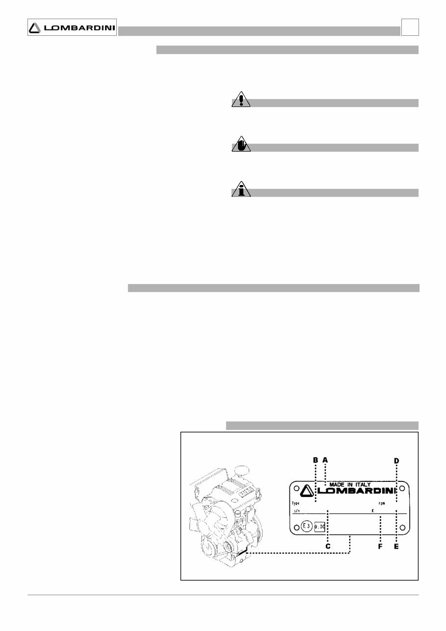
- 5 - Service Manual LDW 502 automotive _ cod. 1.5302.727 - 2° ed_rev. 01 1 GENERAL REMARKS AND SAFETY 1.1 PURPOSE OF THE MANUAL - This manual was written by the manufacturer to provide technical and operating information to authorised LOMBARDINI after-sales service centres to carry out assembly, disassembly, overhauling, replacement and tuning operations. - This information is provided by the manufacturer in its own language (Italian) and may be translated into other languages to satisfy legislative and/or commercial requirements. - As well as employing good operating techniques and observing the right timing for operations, operators must read the information very carefully and comply with it scrupulously. - Time spent reading this information will help to prevent health and safety risks and financial damage. - Written information is accompanied by illustrations in order to facilitate your understanding of every step in the operating phases. - Important remarks and features of the text are highlighted using symbols, which are explained below. Danger – Attention This indicates situations of grave danger, which, if ignored, may seriously threaten the health, and safety of individuals. Caution – Warning This indicates that it is necessary to take proper precautions to prevent any risk to the health and safety of individuals and avoid financial damage. Important This indicates particularly important technical information that should not be ignored. 1.2 USING THIS MANUAL - This manual is divided into several chapters. - The first chapter gives general information and details about safety (purpose of the manual, safety, etc.). - The second, third and fourth chapters provide general technical information (technical specifications, diagrams, tightening torques, malfunctions, etc.). - The fifth, sixth, seventh and eighth chapters describe the most important operating procedures (removal, overhaul and tuning, installation, replacements, etc.). - This final section, which is reserved specifically for LOMBARDINI after-sales service centres, has been prepared with technical and practical considerations in mind. - However, the actual sequence of operations that LOMBARDINI service centres must use may in some cases be different from the ones described in this manual. For this reason, the reader should refer to the index to find his/her topic of interest quickly. 1.3 MANUFACTURER AND ENGINE IDENTIFICATION The identification plate shown in the figure can be found directly on the engine. It contains the model, engine identity and all information needed to operate safely. A) Manufacturer’s identity B) Engine type C) Engine serial number D) Maximum speed E) Customer code E) Approval data
- 6 - Service Manual LW 502 automotive _ cod. 1.5302.727 - 2° ed_rev. 01 1 GENERAL REMARKS AND SAFETY 1.4 GLOSSARY AND TERMINOLOGY For clarity, here are the definitions of a number of terms used recurrently in the manual. - Piston number one: first piston “viewed from the flywheel side of the engine”. - Rotation direction: clockwise or anticlockwise “viewed from the timing belt side of the engine”.. 1.5 WARRANTY CLAUSES LOMBARDINI issues a warranty certificate for each engine giving details of all relevant general terms. 1.6 GENERAL SAFETY REGULATIONS - In designing and building its product, the manufacturer has paid particular attention to those aspects posing a risk to the health and safety of persons handling the engine. In addition to legislative requirements, all “rules for good technical construction” have been applied. - The purpose of this information is to invite operators to pay particular attention in order to prevent any form of risk. Caution is always the best policy. Safety is also the responsibility of all operators who handle the - All persons carrying out work on the engine at any point in its life must possess precise technical qualifications and skills, as well as experience recognised and gained in the specific sector. Non- compliance with these requirements may cause damage to the health and safety of individuals. - Do not tamper with, sidestep, eliminate or bypass the installed safety devices. Non-compliance with this requirement may be hazardous to the health and safety of individuals. - The procedures contained in this manual have been tested and selected by the manufacturer’s technical experts, and hence are to be recognised as authorised operating methods. - A number of procedures must be carried out with the aid of equipment and tools that simplify and improve the timing of operations. - Some of these tools are normal workshop equipment, while others are specific instruments that have been constructed by the engine manufacturer. - All tools must be in good working condition so that engine components are not damaged and that operations are carried out properly and safely. - It is important to wear the personal safety devices prescribed by work safety laws and also by the standards of this manual. - Holes must be lined up methodically and with the aid of suitable equipment. Do not use your fingers to carry out this operation to avoid the risk of amputation. - Some phases may require the assistance of more than one operator. If so, it is important to inform and exercise them regarding the type of activity they will be performing in order to prevent risks to the health and safety of all persons involved. - Do not use flammable liquids (petrol, diesel, etc.) to degrease or wash components. Use special products. - Keep flames away from the engine to avoid the risk of fire. - Replace worn or damaged parts exclusively with original LOMBARDINI spare parts. This will contribute to ensuring better performance and longer product life. 1.7 GENERAL SAFETY DURING OPERATING PHASES
- 7 - Service Manual LDW 502 automotive _ cod. 1.5302.727 - 2° ed_rev. 01 1 GENERAL REMARKS AND SAFETY - Use the oils and greases recommended by the manufacturer. Do not mix different brands or oils with different characteristics. - Use a torque wrench to tighten the main fixing points of engine components. Stick to the tightening torques indicated by the manufacturer. - Discontinue use of the engine if any irregularities arise, particularly in the case of unusual vibrations. - The engine has been designed and built to satisfy all the operating conditions described by the manufacturer. - Do not tamper with any devices to alter the level of performance guaranteed by the manufacturer. In order to minimise the impact on the environment, the manufacturer now provides a number of indications to be followed by all persons handling the engine, for any reason, during its expected lifetime. - All packaging components must be disposed of in accordance with the laws of the country in which disposal is taking place. - Keep exhaust pipes in efficient working order to limit the noise level of the engine and reduce environmental pollution. - When discontinuing use of the engine, select all components according to their chemical characteristics and dispose of separately. - All operations, except where expressly stated otherwise, must be carried out when the engine is not running and has cooled sufficiently to avoid the risk of burns. - Do not keep the engine running in areas that are closed and inadequately ventilated. Take all necessary precautions to prevent a build up of exhaust fumes. Every organisation has a duty to implement procedures to identify, assess and monitor the influence of its own activities (products, services, etc.) on the environment. Procedures for identifying the extent of the impact on the environment must consider the following factors: - Liquid waste - Waste management - Soil contamination - Atmospheric emissions - Use of raw materials and natural resources - Regulations and directives regarding environmental impact - Before removing the engine from the machine on which it is installed, disconnect the electric current, the fuel supply, coolant and all connections including mechanical ones. - To lift the engine, attach the lifting device at the points (eyebolts) specified by the manufacturer. - Close all engine openings carefully (exhaust, intake, etc.) wash the outside and dry with a jet of compressed air. - Anchor the engine to the rotating stand to facilitate all operations. Note:the engine may also be placed on the workbench, depending on the type of work to be carried out. 1.10 PRECAUTIONS WHEN THE ENGINE IS ON THE ROTATING STAND 1.8 SAFETY AND ENVIRONMENTAL IMPACT 1.9 PRECAUTIONS WHEN THE ENGINE IS INSTALLED ON THE MACHINE
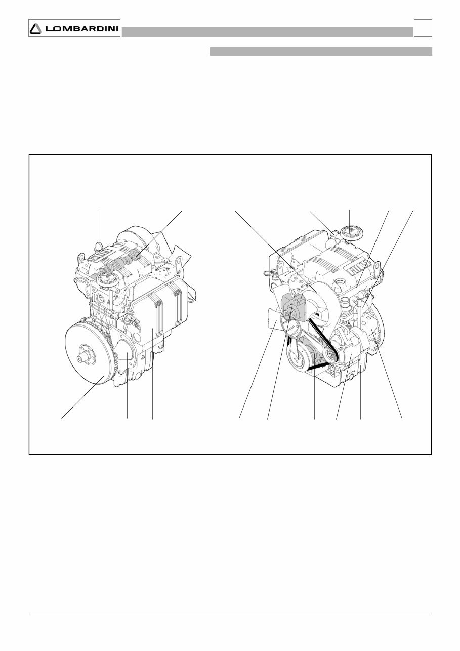
- 9 - Service Manual LDW 502 automotive _ cod. 1.5302.727 - 2° ed_rev. 01 E P F G R T C M B Q D S H A N L 2 Main components A) Cylinder head B) Engine block C) Crankcase D) Timing belt assembly E) Flywheel and crankshaft assembly F) Air intake assembly G) Cooling fan H) Negative-pressure vent valve L) Alternator M) Oil filter N) Exhaust manifold P) Starter motor Q) Camshaft R) Coolant pump S) Fuel supply pump T) Oil pump 2.1 GENERAL DESCRIPTION OF THE ENGINE TECHNICAL INFORMATION
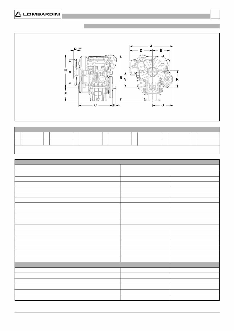
- 10 - Service Manual LW 502 automotive _ cod. 1.5302.727 - 2° ed_rev. 01 A B C D 36 280 E G 451 491 N P 181 213 H M R S 340 151 182 160 Q 51( 1 ) 52( 2 ) 353 238 n° mm cm 3 2 72x62 505 μm cm 2 13÷14 4470 Kg 60 35° 25° 910 36 Nl/min m 3 /min 22,8:1 1:2 3600 9.8 (13.4) 9.1 (12.4) 8.2 (11.2) 28.7 300 kW (CV) kW (CV) kW (CV) Nm Kg 2 2.2 TECHNICAL SPECIFICATIONS DIMENSIONS (mm) GENERAL DETAILS Operating cycle Number of cylinders Bore x stroke Displacements Compression rate Intake Filter capacity Filtering surface Cooling Driving shaft rotation Combustion sequence Timing system Dry weight of engine Maximum tilt while operating Maximum tilt while operating Volume of air flow (at 3600 RPM) Volume of cooling air (at 3600 RPM) (1) with suction fan (2) with blower fan Maximum operating speed Max. power (N 80/1269/EEC - ISO 1585 - DIN 7020) Max. power (NB ISO 3046 - 1 IFN - DIN 6270) Max. power (NA ISO 3046 - 1 ICXN - DIN 6270) Maximum torque (at 2400 RPM) Axial load allowed on driving shaft POWER AND TORQUE 4-stroke diesel no more than 1 minute no more than 30 minutes Air filter (dry) Water Clockwise (from distribution side) Synchronous toothed belt RPM TECHNICAL INFORMATION
The Lombardini Marine Engines LDW 502 SERVICE MANUAL is a comprehensive guide tailored to assist both professional mechanics and DIY enthusiasts in servicing and maintaining their LDW 502 marine engines. It contains detailed instructions, diagrams, and specifications for all aspects of engine maintenance, including troubleshooting, repair procedures, and routine maintenance tasks. The manual covers all models of the LDW 502 marine engines, ensuring that you have the correct information for your specific engine model.
Designed for easy navigation and understanding, this service manual is a valuable resource for anyone working on or owning a Lombardini LDW 502 marine engine. Purchase the Lombardini Marine Engines LDW 502 SERVICE MANUAL today to ensure proper care and maintenance of your engine.







 Lifetime Access




