


Administrator X4IQAT1XJQSU1TP printed this protected Document 'D904_D906_D914_D916_D924_D926_ 8718458_04092008_v02_en.pdf' Friday, 01.January 2010 19:59

Administrator X4IQAT1XJQSU1TP printed this protected Document 'D904_D906_D914_D916_D924_D926_ 8718458_04092008_v02_en.pdf' Friday, 01.January 2010 19:59

Foreword
This manual includes the major points for proper maintenance, adjustments and repairs with technical
data and screw tightening torques for Liebherr Diesel engine D 904 / 906 / 914 / 916 / 924 / 926.
These tasks must be carried out by trained professionals.
The Service manual will not be updated. For that reason, we always refer to additional Service
Information bulletins. All changes will be incorporated when the Service manual is reissued
periodically.
No part of this documentation may be reproduced or copied without our explicit written permission.
This Service manual was written by Liebherr-Machines-Bulle S.A., Dept. Service – Diesel - Engine
and issued by the Service Dept., Liebherr Hydraulikbagger GmbH, Kirchdorf/Iller, Dept. VS.
All changes reserved. LIEBHERR-MACHINES-BULLE SA
All rights reserved. Dept.: Service – Diesel – Engine
Issue: Id. No.
12 / 2003 8718458 (English)
Administrator X4IQAT1XJQSU1TP printed this protected Document 'D904_D906_D914_D916_D924_D926_ 8718458_04092008_v02_en.pdf' Friday, 01.January 2010 19:59

Administrator X4IQAT1XJQSU1TP printed this protected Document 'D904_D906_D914_D916_D924_D926_ 8718458_04092008_v02_en.pdf' Friday, 01.January 2010 19:59

Index
1) Engine illustrations
2) Technical description
3) Engine description, engine data tag, cylinder description, direction of rotation
and engine identification number
4) Engine data, adjustment values, operating pressures, operating temperatures
and fluid quantities
5) Torque specifications
6) Valve adjustment
7) Cylinder head gaskets
8) Cylinder head
9) Cylinder liner
10) Piston and connecting rod
11) Check piston clearance
12) Crankshaft an bearing
13) Camshaft and valve drive
14) Lubrication circuit
15) Oil pans
16) Lube oil pump
17) Lube oil filter and oil cooler
18) Coolant circuit
19) Water filter
20) Coolant pump
21) Fan drive
22) Fuel system
23) Fuel pump
24) Fuel filter
25) Injection pump
26) Injection pump drive, adjust begin of delivery
27) Fuel injector
28) Engine exhaust
29) Fan and flywheel side crankshaft seal
30) Hydraulic pump auxiliary drive
31) Air compressor
32) Starter
33) Air conditioner compressor and alternator
34) Starting aid
35) Turbo charger
36) Gear drive
37) Maintenance and inspection
38) Service fluids
39) Troubleshooting
40) Special tools
Administrator X4IQAT1XJQSU1TP printed this protected Document 'D904_D906_D914_D916_D924_D926_ 8718458_04092008_v02_en.pdf' Friday, 01.January 2010 19:59

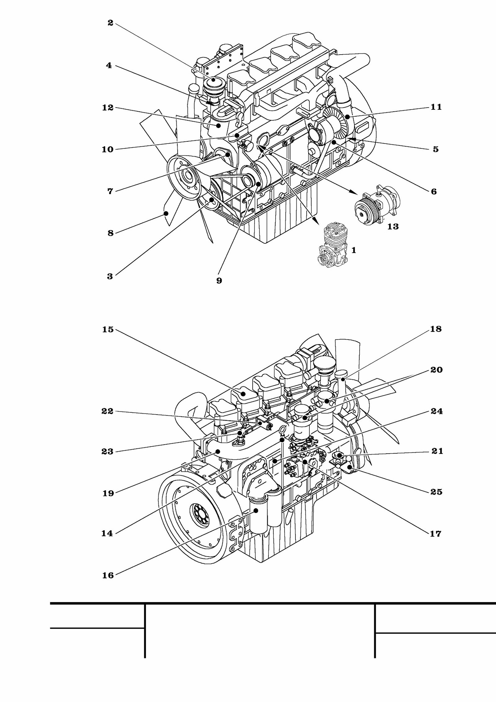
1 Engine illustrations
Engine view: Left , as seen from the flywheel side onto the engine
1 Air compressor
2 Oil separator
3 V-belt - crankshaft
4 Coolant temperature sensor
5 Oil pressure sensor (with warning contact)
6 Starter
7 Coolant pump
8 Fan
9 Alternator
10 Coolant thermostat
11 Exhaust turbocharger
12 Water filter
13 Air conditioner compressor
Engine view: Right, as seen from the flywheel side onto the engine
14 Oil dipstick
15 Valve cover
16 Oil filter
17 Injection pump
18 Oil filler neck
19 Suction pipe
20 Fuel filter
21 Fuel pump
22 Solenoid valve (flame glow plug)
23 Flame glow plug
24 Data tag
25 Hydraulic pump auxiliary drive
Administrator X4IQAT1XJQSU1TP printed this protected Document 'D904_D906_D914_D916_D924_D926_ 8718458_04092008_v02_en.pdf' Friday, 01.January 2010 19:59
MJFCIFSS
Datum / Edition / Date
12 / 2003
Benennung / Description / Denomination
Typ
Model
Type
Blatt
Page
Feuille
Engine illustration
D 904 / 914 / 924
D 906 / 916 / 926
1
Administrator X4IQAT1XJQSU1TP printed this protected Document 'D904_D906_D914_D916_D924_D926_ 8718458_04092008_v02_en.pdf' Friday, 01.January 2010 19:59

2 Technical description
Engine design
Water-cooled, 4 and 6 cylinder in-line engines with LIEBHERR direct injection process and
exhaust turbocharger.
Characteristics
A sturdy basic construction and generous dimensions provide the foundation for high
operating safety and long service life. Low fuel consumption, low noise and exhaust
emissions are achieved through a combustion process, which is specially adapted to
requirements. Low maintenance effort on easily accessible components and a variety of
optional accessories ensure good overall efficiency.
Power transmission
The 4 cylinder engines feature a steel crankshaft with 5 bearings, the 6 cylinder engines 7
bearings, with inductively hardened bearing surfaces and 8 / 12 forged counterweights. A
vibration damper is installed on the fan side on the crankshaft. Forge-pressed, split connecting
rod, leaded bronze tri-metal sliding bearings or sputter bearings, smooth shaft three ring piston
of aluminum alloy with ring support and combustion recess in the piston base.
Exchangeable, wet cylinder liners
Housing
The crankcase is made in one unit of alloy cast iron. Single cylinder heads with integrated
intake channel and removable / exchangeable valve seat rings and valve guides. Flywheel
housing, front timing case and oil pan on the underside close off the engine.
Engine timing
Per cylinder one intake and exhaust valve each, suspended in the cylinder head (ohv.).
Actuated by a steel camshaft with 5 or 7 bearings via steel tappets, push rod and rocker arm.
Drive of camshaft, injection pump, lube oil pump, air compressor, coolant pump, and auxiliary
hydraulic pumps by the crankshaft via nitride gears on the fan side.
Lubrication
Force-feed lubrication with gear pump for crankshaft, connecting rod and camshaft bearings
as well as piston pin bushing, tappet and rocker arm.
Oil filtration via two replaceable filter elements in the main oil circuit. Auxiliary components as
well as injection pump and air compressor are connected to engine lubrication circuit. The
engine oil cooler is integrated in the coolant flow.
Cooling
Dual thermostatically regulated fluid cooling with rotary pump. Individual supply of each
cylinder unit via distributor channels integrated in the crankcase.
Piston cooling through oil spray from engine lubrication circuit.
Fuel injection system and regulation
Maintenance free BOSCH in line injection pump or distributor pump with mechanical BOSCH
centrifugal regulator. On A4, A5 - engines with „EDC“ control (electronic regulation), fuel
pump with fuel filter, BOSCH four or six hole nozzles.
Administrator X4IQAT1XJQSU1TP printed this protected Document 'D904_D906_D914_D916_D924_D926_ 8718458_04092008_v02_en.pdf' Friday, 01.January 2010 19:59

Flame starter
The flame starter is a cold starting assistance for low ambient temperature. It minimizes the
emission of white smoke after starting the diesel engine. By reducing the starting period, the
starter and the batteries will be saved.
The flame spark plug, mounted in the air intake, will get fuel via a solenoid valve with dosaging
nozzle and could set free.
Electrical equipment
Starter and alternator: 24 Volt
Electronic sensors controlling the engine parameters
Air charge pressure sensor, temperature sensor at cooling agent and air charge, rotation
sensor and oil pressure sensor are indicators for the external control functions. Each function
and error signal is described in the corresponding user manual.
MJFCIFSS
Datum / Edition / Date
12 / 2003
Benennung / Description / Denomination
Typ
Model
Type
Blatt
Page
Feuille
Technical description
D 904 / 914 / 924
D 906 / 916 / 926
2
Administrator X4IQAT1XJQSU1TP printed this protected Document 'D904_D906_D914_D916_D924_D926_ 8718458_04092008_v02_en.pdf' Friday, 01.January 2010 19:59

Administrator X4IQAT1XJQSU1TP printed this protected Document 'D904_D906_D914_D916_D924_D926_ 8718458_04092008_v02_en.pdf' Friday, 01.January 2010 19:59
You're Reading a Preview
What's Included?
 Lifetime Access
Fast Download Speeds
Online & Offline Access
Access PDF Contents & Bookmarks
Full Search Facility
Print one or all pages of your manual
$39.99
Liebherr D924te D924ti-e D926te Diesel Engine Full Service & Repair Manual
Viewed 17 Times Today

What's Included?
Lifetime Access
Fast Download Speeds
Online & Offline Access
Access PDF Contents & Bookmarks
Full Search Facility
Print one or all pages of your manual
$39.99

Secure transaction
What's Included?
Lifetime Access
Fast Download Speeds
Online & Offline Access
Access PDF Contents & Bookmarks
Full Search Facility
Print one or all pages of your manual
- This is a complete factory service repair workshop manual for the Liebherr D924te, D924ti-e, D926te diesel engine.
- The manual is available for instant access on your computer, tablet, or smartphone.
- It covers all repairs, servicing, and troubleshooting procedures with detailed photos and diagrams.
- Professional mechanics and technicians use this manual, which contains step-by-step instructions and highly detailed exploded diagrams and pictures.
- You can print out a single page or the entire manual as per your choice.
- This manual can be used on multiple computers without any limitations or trial periods.
- There is no expiry date, renewal fee, or need to pay extra for continued use.
- It is fully compatible with all Windows and MAC computers.
Thanks for considering this manual. Click the button for more information.


