Kubota V1200-B Diesel Engine OEM Service & Repair Manual
What's Included?
Lifetime Access
Fast Download Speeds
Online & Offline Access
Access PDF Contents & Bookmarks
Full Search Facility
Print one or all pages of your manual
WORKSHOP MANUAL DIESEL ENGINE MOTEUR DIESEL MANUAL D'ATELIER WERKSTATTAN LElTU NG DIESELMQTOR 70mm STROKE SERIES MOTEUR DE 70mm DE COURSE SERIENMOTOR MIT 70mm HUB Redistribution or publication of this document by any means, is strictly prohibited.
Redistribution or publication of this document by any means, is strictly prohibited.
TO THE READER This Workshop Manual has been prepared t o provide servicing personnel with information on the mechanism, service and maintenance of KUBOTA Diesel Engines 70 mm STROKE SERIES. It is divided into two parts, "Mechanism" and "Disassembling and Servicing". Mechanism Information on construction and functions are included for each engine section. This part should be understood before proceeding with trouble- shooting, disassembling and servicing. 1 Disassembling and Servicing Under the heading "General" come general precautions, troubleshooting, lists of servicing specifications and periodic inspection items. For each engine section, there are If Checking and Adjustment", If Disassembllng and Assembling", and "Servicing" which cover procedures, precautions, factory specification and allowable limits. All information, illustrations and specifications contained in this manual are based on the latest production information available at the time of publication. The right is reserved t o make changes in all information at any time without notice. Due t o covering many models of this manual, illustration or picture being used have not been specified as one model. Apr. '88 @ KUBOTA Corporation 1990 INTRODUCTION Ce manuel d'atelier a et6 prepare pour permettre au personnel d'entretien de disposer d'informations sur les mecanismes, les entretiens et la maintenance des moteurs Kubota Diesel moteur de serie a 70 mm de course. I1 est divise en deux sections: "Mecanismes" et "Demontage et entretien". 1 Mecanisme Des informations sur la construction et les fonctions sont donnees pour chaque partie du moteur. Cette partie du manuel doit @tre comprise avant que I'oncommence les operations de recherche des anomalies, de demontage et d'entretien. Demontage et entretien Sous le titre "Generalites" on trouvera des precautions generales, les procedures de recherche des anomalies et les listes de caracteristiques d'entretien et items de verification pCriodique. Pour chaque partie du moteur, on trouvera les titres "Verification et reglage", " Dhontage et remontage" et "Entretien" oir sont reprises les precautions,. les caracteristiques d'usine et les limite de service. Toutes lees informations, illustrations et specifications contenues dans ce manuel sont basees sur les dernieres informations de production disponibles au moment de la publication. Nous nous reservons le droit de modifier tout 6ICment de ces infomations, ? I tout moment et sans preavis. Ce manuel couvrant de nombreux modeles, les illustrations ou photos utilisees sont donnkes a titre indicatif. Avr. '88 @ KUBOTA Corporation 1990 Redistribution or publication of this document by any means, is strictly prohibited.
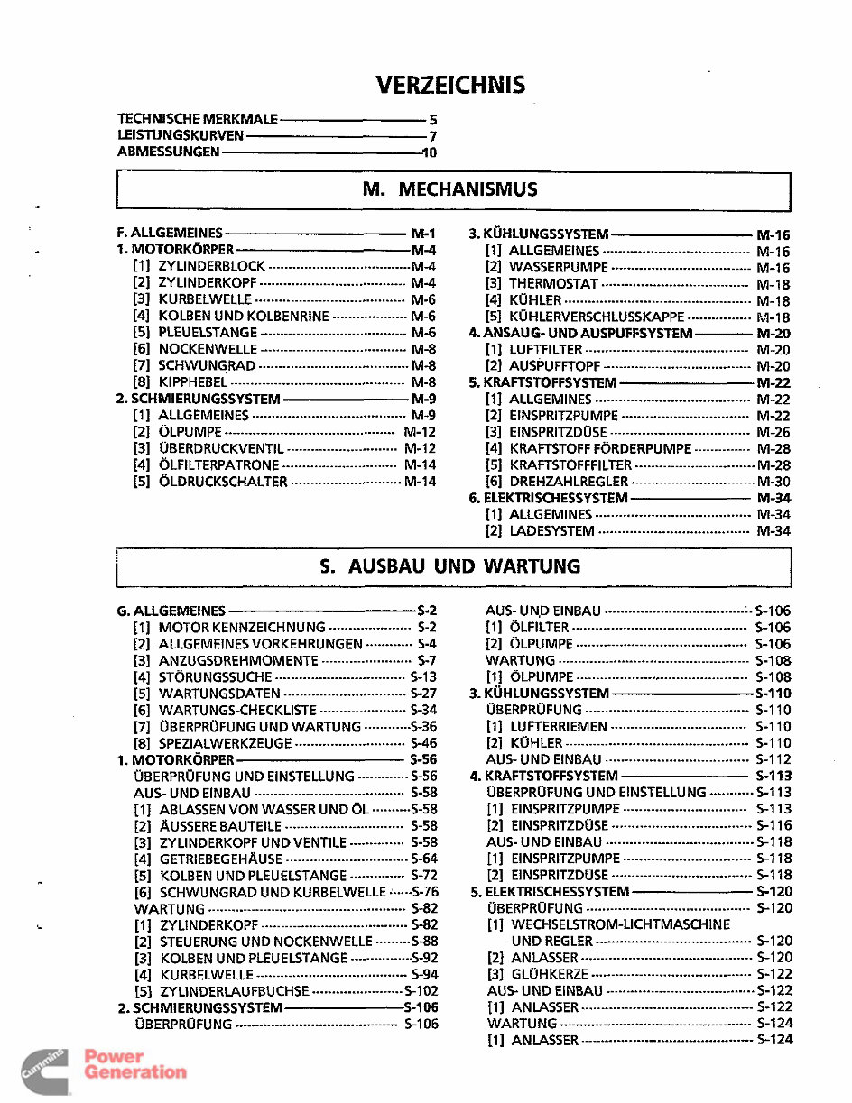
FUR DEN LESER Dieses Handbuch sol1 dem Wartungspersonanl lnformationen uber die Funktion, den Betrieb und die Wartung der KUBOTA-Dieselmotoren Serienmotormit 70 mm Hub liefern. Es ist in zwei Teile, "Funktion" und "Ausbau und Wartung" aufgegliedert. H Mechanismus Fur jeden Motorabschnitt werden Informationen bezuglich Konstruktion und Funktion gegeben. Dieser Teil sollte sorgfaltig gelesen werden, bevor mit der Storungssuche, dern Ausbau und der Wartung begonnen wird. Ausbau und Wartung Der Abschnitt "allgemeines" beinhaltet allgemeine Vorkehrungen, Storungs- suchen und Listen von Wartungsdaten sowie von regelmaRig zu Oberprufenden Teilen. Fur jeden Motorabschnitt ist ein Kapitel "Prufung und Einstellung", "Aus- und Einbau" und "Wartung" vorgesehen, welches uber Verfahrensweisen, Vorkehrungen, Werkdaten und zulassige Grenzwerte AufschluR gibt. Allen in diesem Hanbuch enthaltenen Informationen, Abbildungen und technischen Merkmalen liegen die letzten, zum Zeitpunkt der Veroffentlichung verfugbaren lnformationen zugrunde. Eine Anderung aller lnformationen t u jeder Zeit und ohne Ankundigung bleibt vorbehalten, Da in diesem Handbuch mehrere Modelle beschrieben werden, wurden die jeweilig verwendeten abbildungen oder Bilder nicht fur ein einzelnes Modell prazisiert. Apr. '88 @ KUBOTA Corporation 1990 Redistribution or publication of this document by any means, is strictly prohibited.
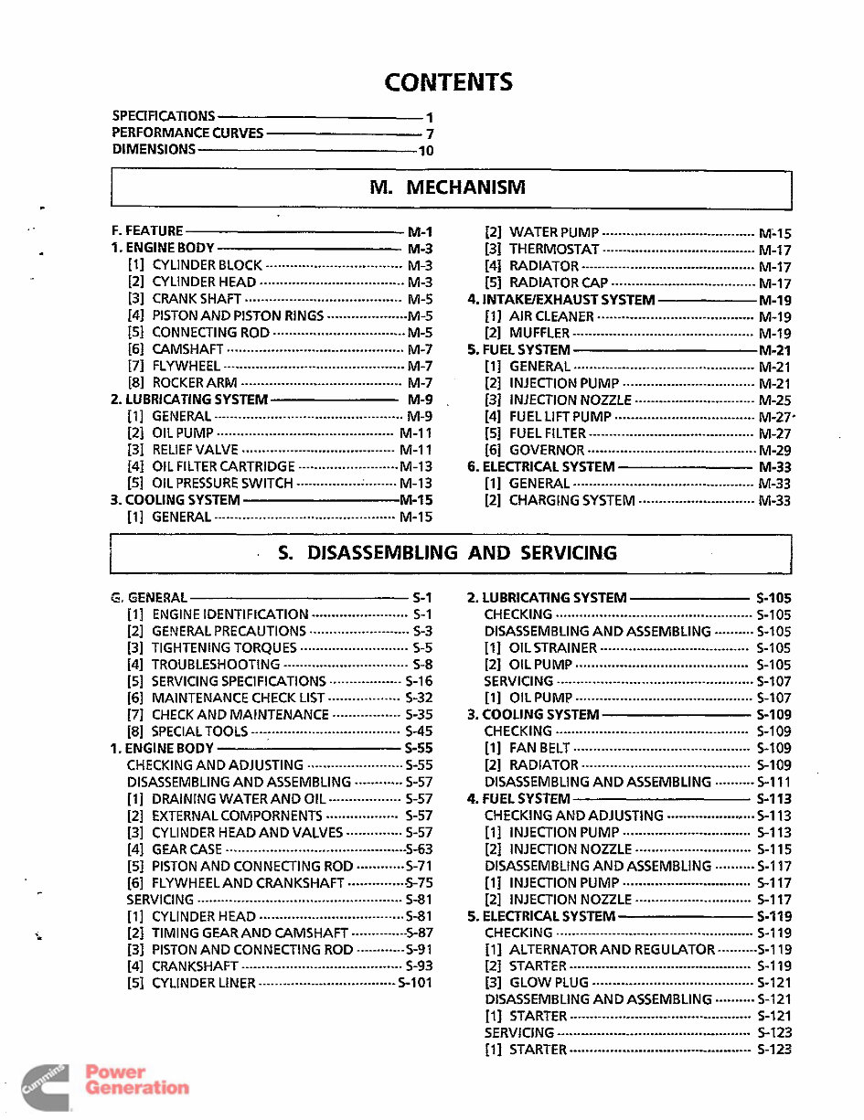
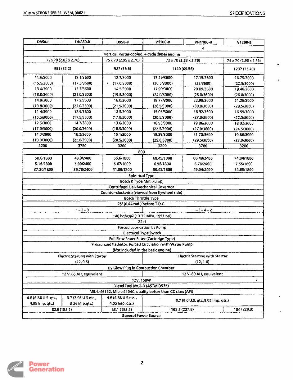
CONTENTS SPECIFICATIONS 1 PERFORMANCE CURVES 7 DIMENSIONS 10 M. MECHANISM L ...................................... F. FEATURE M-1 [2] WATER PUMP M-15 ...................................... 1. ENGINE BODY M-3 131 THERMOSTAT M-17 [I] CYLINDER BLOCK M-3 141 RADIATOR M-17 [2] CYLINDER HEAD M-3 151 RADIATOR M-17 131 CRANK SHAFT M-5 4. INTAKWEXHAUST SYSTEM M-19 [4] PISTONAND PISTON RINGS --------------*----- M -5 M-19 [51 CONNECTING ROD M-5 [2] MUFFLER M-19 [6] CAMSHAFT M-7 5. FUEL SYSTEM M-21 171 FLYWHEEL M-7 [I] GENERAL M-2 1 [a] ROCKER ARM M -7 [2] INJECTION PUMP M-2 1 2. LUBRICATING SYSTEM M-9 . [3] INJEflION NOZZLE M-25 [I] GENERAL M-9 141 FUEL LIFT PUMP M-27. [2] OIL PUMP M-1 1 151 FUEL FILTER M-27 [31 RELIEF VALVE M-11 [6] GOVERNOR M-29 [4] OIL FILTER CARTRIDGE M-13 6. ELECTRICAL SYSTEM M-33 151 OIL PRESSURE SWITCH ' M-13 [I] GENERAL M-33 [I] GENERAL M-15 .................................. ........................................... .................................... .................................... ....................................... ....................................... [I] AIR CLEANER ................................. ............................................. ............................................ ............................................. ............................................. ........................................ ................................. .............................. ............................................... ................................... ............................................ ......................................... ...................................... .......................................... ......................... ......................... ............................................. 3. COOLING SYSTEM M-15 [2] CHARGING SYSTEM ............................. M-33 ............................................. I . S. DISASSEMBLING AND SERVIC1N.G I i G. GENERAL s-1 [I] ENGINE lDENTlFlCATlON 5-1 121 GEb!EWL PRECAUTIONS 5-3 131 TIGHTENING TORQUES 5-5 [5] SERVICING SPECIFICATIONS .................. S-16 [6] MAINTENANCE CHECK LIST .................. 5-32 [7] CHECK AND MAINTENANCE ................. 5-35 [a] SPECIALTOOLS 5-45 1. ENGINE BODY s-55 CHECKINGAND ADJUSTING 5-55 DISASSEMBLINGAND ASSEMBLING ---------*-- 5-57 [ll DRAINING WATER AND OIL .................. 5-57 [2] EXTERNAL COMPORNENTS ----*-----------*- 5-57 [3] CYLINDER HEAD AND VALVES .............. 5-57 [41 GEAR CASE 5-63 [5] PISTONAND CONNECTING ROD ............ 5-71 [6] FLYWHEEL AND CRANKSHAFT --------------- 5-75 ........................ ......................... ........................... ............................... [41 TROUBLESHOOT~NG 5-8 ..................................... ........................ ............................................. ................................................... 5-8 1 .................................... CYLINDER HEAD 5-8 1 TIMING GEAR AND CAMSHAFT ----*--------- 5-87 PISTONAND CONNECTING ROD ------------ s-9 1 CRANKSHAFT 5-93 CYLINDER LINER 5-101 ........................................ .................................. 2. LUBRICATING SYSTEM S-1 OS CHECKING S-105 DISASSEMBLINGAND ASSEMBLING .......... 5-1 05 [I] OIL STRAINER 5-1 05 [2] OIL PUMP 5-105 SERVICING 5-107 [I] OIL PUMP 5-107 3. COOLING SYSTEM s-I09 CHECKING 5-109 [I] FAN BELT 5-109 [2] RADIATOR 5-1 09 DISASSEMBLINGAND ASSEMBLING .......... 5-1 11 4. FUEL SYSTEM S-I 13 CHECKING AND ADJUSTING ------.-.----.-.--,..- 5-1 13 [I] INJECTION PUMP 5-1 13 [2] INJECTION NOZZLE 5-1 15 DISASSEMBLINGAND ASSEMBLING ---------- 5-1 17 [I] INJECTION PUMP 5-1 17 [2] INJECTION NOZZLE 5-1 17 5. ELECTRICAL SYSTEM s-119 CHECKING 5-119 [l] ALTERNATORAND REGULATOR-------- s-119 [2] STARTER 5-119 131 GLOW PLUG 5-121 DISASSEMBLINGAND ASSEMBLING ---------- 5-1 21 [I] STARTER 5-1 21 SERVJCINC 5-1 23 [I] STARTER--------------..--.--.----..-.---.-.*---..-- 5-123 ................................................. ..................................... ........................................... ................................................. ............................................ ................................................ ............................................ .......................................... ................................ ............................. ................................ ............................. ................................................. ............................................. ........................................ ............................................. ................................................ Redistribution or publication of this document by any means, is strictly prohibited.
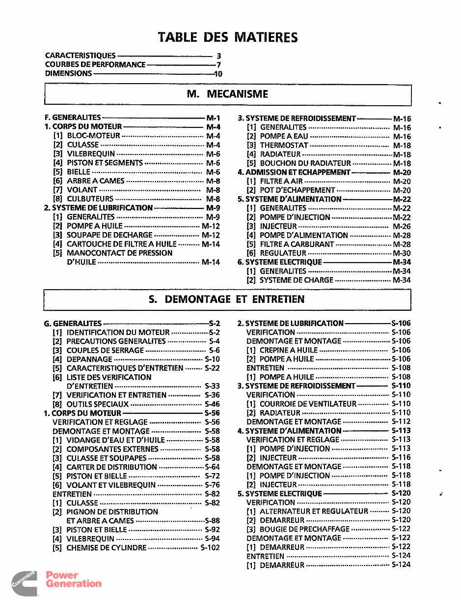
TABLE DES MATIERES CARACTERlSTlQUES 3 COURBES DE PERFORMANCE 7 DIMENSIONS 10 M. MECANISME 1 F. GENERALITES M-1 1. CORPS DU MOTEUR M-4 ...................................... [I] BLOC-MOTEUR M-4 [2] CULASSE M-4 [3] VlLEBREQUlN M-6 [4] PISTON ETSEGMENTS M-6 [5] BIELLE M-6 [6] ARBRE A CAME5 M-8 [7] VOLANT M-8 [a] CULBUTEURS M-8 2. SYSTEME DE LUBRlFlCAllON M-9 [I] GENERALlTES M-9 [z] POMPEA HUlLE M-12 [3] SOUPAPE DE DECHARGE ..................... M-12 [4] CARTOUCHE DE FILTREA HUILE ----*----* M-14 [SI MANOCONTACT DE PRESSION D'HUILE M-14 ................................................ ........................................ ........................... ................................................... .................................... ............................................... ........................................ ........................................ ................................... ............................................... 3. SYSTEME DE REFROIDISSEMENT M-16 [I] GENERALlTES M-16 [2] POMPEA ..................................... M-16 [3] THERMOSTAT M-18 141 ~DIATEUR M-18 [5] BOUCHON DU RADlATEUR..-.- ...... - ...... M-18 4. ADMISSION ET ECHAPPEMENT M-20 [I] FlLTREAAIR M-20 [2] POT D'ECHAPPEMENT M-20 5. SYSTEME D'ALIMENTAnON M-22 [I] GENERALlTES M-22 [2] POMPED'INJECTION M-22 [3] INJEUEUR M-26 [4] POMPE D'ALIMENTATION *.--.-----.**--**-- M-28 [51 FILTRE A CARBURANT M-28 [6] REGUMTEUR M-30 6. SYSTEME ELECTRIQUE M-34 [I] GENEMLlTES M-34 ...................................... ..................................... .......................................... ........................................ ......................... ....................................... ............................ .......................................... .......................... ....................................... ....................................... [2] SYSTEME DE CHARGE .......................... M-34 I S. DEMONTAGE ET ENTRETIEN I G. GENERAUTES s-2 [l] IDENTIFICATIONDU MOTEUR -..-.-- .... ---.-.-S -2 [2] PRECAUTIONSGENERALITES .................. 5-4 [4] DEPANNAGE ......................................... s-10 [5] CARACTERISTIQUESD'ENTRETIEN .-*.---- 5-22 D'ENTRETIEN 5-33 [7] VERIFICATION ET ENTRETIEN ..**--*-----**- 5-36 [8] OUTlLS SPEClAUX S-46 1. CORPS DU MOTEUR S-56 VERIFICATION ET REGLAGE ........................ 5.56 DEMONTAGE ET MONTAGE ....................... 5-58 [l] VIDANGE D'EAU ET D'HUILE *--*.-.-.*------- 5-58 [2] COMPOSANTES EXTERNES *-----**---*.-***-* 5-58 [3] CULASSE ETSOUPAPES ......................... 5-58 [4] CARTER DE DISTRIBUTION ..................... 5-64 [SI PISTON ET B~ELLE ................................. s-72 [6] VOLANT ET VILEBREQUIN ..-.-..-.-..----..--- 5-76 ENTRETIEN .................................................. 5-82 [I] CULASSE ............................................... 5-82 [2] PIGNON DE DISTRIBUTION ETARBRE A CAMES ................................ 5-88 131 PISTON ET B~ELLE .................................. s-92 141 V~LEBREQU~N ........................................ 5-94 [3] COUPLES DE SERRAGE ............................ 5-6 [6] LISTE DESVERIFICATION ........................................ ................................. [SI CHEMISE DE CYLINDRE ....................... S-102 2. SYSTEME DE LUBRlFlCAllON S-106 VERlFlCATlON ........................................... S-106 DEMONTAGE ET MONTAGE ...................... S-106 [I] CREPlNE A HUlLE ................................ 5-106 [2] POMPEA HUlLE ................................... 5-106 ENTRETlEN ............................................... 5-108 [ 11 POMPEA HUlLE .................................. S-108 s-1 10 VERlFlCATlON ........................................... S-110 [l] COURROIE DE VENTILATEUR --------*.-.-- s-110 [2] MDlATEUR ......................................... S-1 10 DEMONTAGE ET MONTAGE ..................... 5-112 4. SYSTEME D'ALIMENTATION S-113 3. SYSTEME DE REFROIDISSEMENT VERIFICATION ET REGLAGE ...................... S-113 [I] POMPE D'INJEOION .......................... 5-113 [2] INJEOEUR .......................................... S-1 16 DEMONTAGE ET MONTAGE ..................... 5-118 [I] POMPE ~'l~j~~l-10~ .......................... s-118 5. SYSTEME ELECTRIQUE s-I 20 [l 1 ALTERNATEUR ET REGULATEUR .-----..* 5-120 [2] INJECTEUR .......................................... 5-1 18 VERIFICATION ........................................... S-120 [2] DEMARREUR ....................................... 5-120 [3] BOUGIE DE PRECHAFFAGE ****.**9***.-*-*-. 5-122 DEMONTAGE ET MONTAGE ..................... 5-122 [l] DEMARREUR ....................................... $122 ENTRET~EN ................................................ s-124 111 DEMARREUR ....................................... 5-124 i Redistribution or publication of this document by any means, is strictly prohibited.
This workshop service manual for the Kubota V1200-B Diesel Engine OEM Service & Repair Manual is designed for mechanical technicians who are familiar with service procedures for Kubota products. It covers complete repair and overhaul procedures, including instructions on components and systems manufactured specifically for the Kubota V1200-B Diesel Engine. The manual provides reliable, up-to-date information and emphasizes critical details indicated by the symbols: WARNING, CAUTION, and NOTE.
It includes comprehensive diagnostic and repair procedures, along with clear instructions for routine maintenance and servicing. Whether you are a professional mechanic or a dedicated DIY enthusiast, this manual serves as an essential resource for the maintenance and repair of your Kubota V1200-B Diesel Engine. The manual also stresses the importance of safety equipment and proper precautions when working on the engine, including the proper use of a torque wrench and special tools required for adjustments and repairs.
The manual offers detailed specifications and step-by-step procedures approved by an authorized Kubota V1200-B Diesel Engine dealer service department. It is designed to help users maximize the performance and longevity of their Kubota engine by providing critical information on tune-ups, maintenance, removal and installation procedures, assemblies and disassemblies, fuel systems, ignition, lubrication, exhaust, electrical systems, and more.
Please note that this is a .PDF manual – not interactive software. The content within represents the parts and procedures relevant to the specific product configuration at the time of publication, and it is available for fast electronic delivery via email and is printable in English.
For those undertaking maintenance and repair work on their Kubota V1200-B Diesel Engine, this OEM Service & Repair Manual is a comprehensive resource that includes all necessary instructions to address any repair requirements of the engine effectively.
General Information
Maintenance
Lubrication
Heating
Ventilation
Air Conditioning
Suspension
Front Suspension
Rear Suspension
Wheel
Tire System
Differential
Driveline
Drive Shaft
Transfer Case
Brakes
Engine
Engine Mechanical
Engine Cooling
Engine Fuel
Engine Electrical
Ignition System
Starting
Charging System
Emissions
Engine Exhaust
Engine Lubrication
Engine Speed Control System
Clutch
Cooling
Electronic Control Modules
AND SO MUCH MORE...
Recently Viewed
5,521,897Happy Clients
2,594,462eManuals
1,120,453Trusted Sellers
15Years in Business
Price:
Actual Price:
Kubota V1200-B Diesel Engine OEM Service & Repair Manual