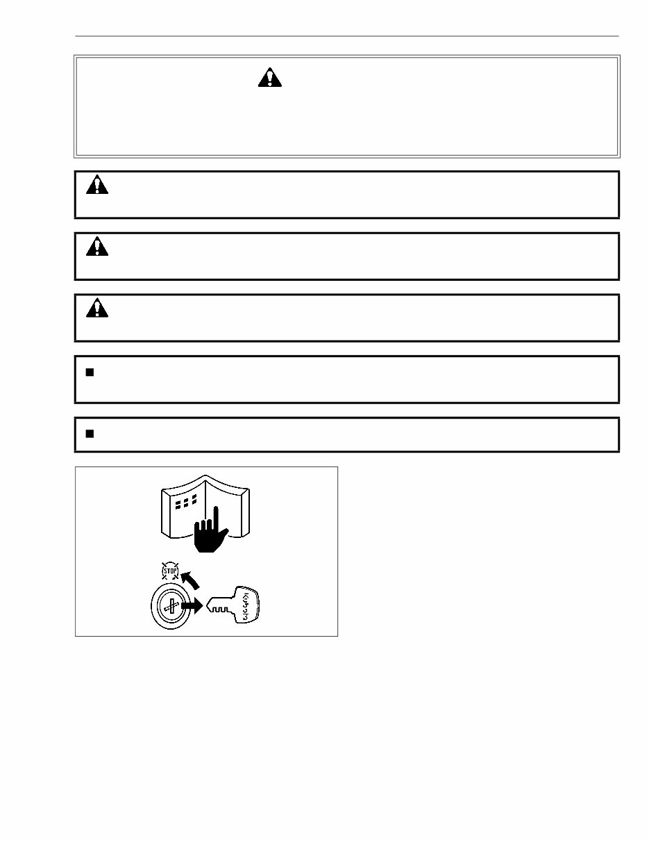
1 SAFETY INSTRUCTIONS 03-M-DI Series, WSM BEFORE SERVICING AND REPAIRING • Read all instructions and safety instructions in this manual and on your engine safety decals. • Clean the work area and engine. • Park the machine on a firm and level ground. • Allow the engine to cool before proceeding. • Stop the engine, and remove the key. • Disconnect the battery negative cable. • Hang a “DO NOT OPERATE” tag in operator station. SAFETY FIRST This symbol, the industry’s “Safety Alert Symbol”, is used throughout this manual and on labels on the machine itself to warn of the possibility of personal injury. Read these instructions carefully. It is essential that you read the instructions and safety regulations before you attempt to repair or use this unit. DANGER : Indicates an imminently hazardous situation which, if not avoided, will result in death or serious injury. WARNING : Indicates a potentially hazardous situation which, if not avoided, could result in death or serious injury. CAUTION : Indicates a potentially hazardous situation which, if not avoided, may result in minor or moderate injury. IMPORTANT : Indicates that equipment or property damage could result if instructions are not followed. NOTE : Gives helpful information. KiSC issued 10, 2009 A
2 03-M-DI Series, WSM SAFETY INSTRUCTIONS SAFETY STARTING • Do not start the engine by shorting across starter terminals or bypassing the safety start switch. • Unauthorized modifications to the engine may impair the function and / or safety and affect engine life. SAFETY WORKING • Do not work on the machine while under the influence of alcohol, medication, or other substances or while fatigued. • Wear close fitting clothing and safety equipment appropriate to the job. • Use tools appropriate to the work. Makeshift tools, parts, and procedures are not recommended. • When servicing is performed together by two or more persons, take care to perform all work safely. • Do not touch the rotating or hot parts while the engine is running. • Never remove the radiator cap while the engine is running, or immediately after stopping. Otherwise, hot water will spout out from radiator. Only remove radiator cap when cool enough to touch with bare hands. Slowly loosen the cap to first stop to relieve pressure before removing completely. • Escaping fluid (fuel or hydraulic oil) under pressure can penetrate the skin causing serious injury. Relieve pressure before disconnecting hydraulic or fuel lines. Tighten all connections before applying pressure. • Wear a suitable hearing protective device such as earmuffs or earplugs to protect against objectionable or uncomfortable loud noises. AVOID FIRES • Fuel is extremely flammable and explosive under certain conditions. Do not smoke or allow flames or sparks in your working area. • To avoid sparks from an accidental short circuit, always disconnect the battery negative cable first and connect it last. • Battery gas can explode. Keep sparks and open flame away from the top of battery, especially when charging the battery. • Make sure that no fuel has been spilled on the engine. KiSC issued 10, 2009 A
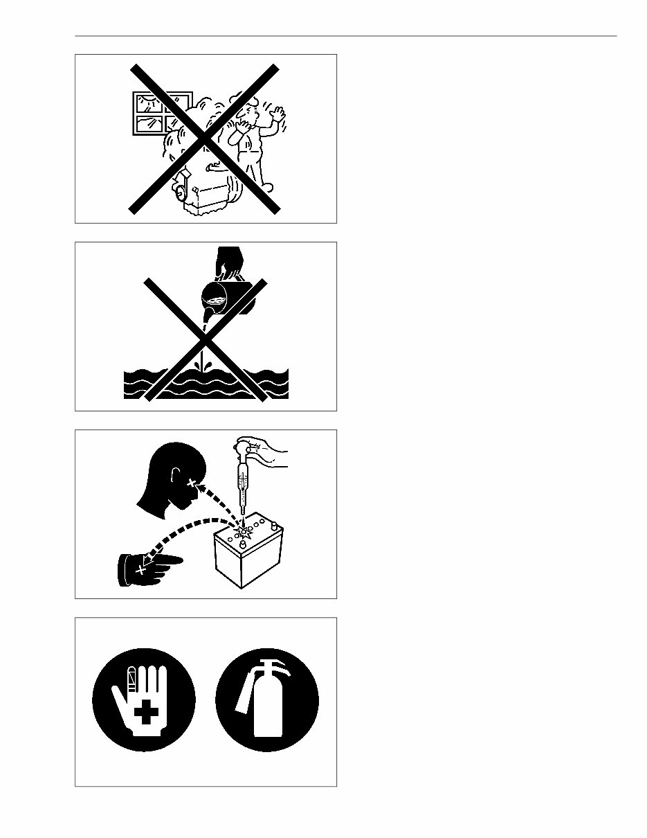
3 SAFETY INSTRUCTIONS 03-M-DI Series, WSM VENTILATE WORK AREA • If the engine must be running to do some work, make sure the area is well ventilated. Never run the engine in a closed area. The exhaust gas contains poisonous carbon monoxide. DISPOSE OF FLUIDS PROPERLY • Do not pour fluids into the ground, down a drain, or into a stream, pond, or lake. Observe relevant environmental protection regulations when disposing of oil, fuel, coolant, electrolyte and other harmful waste. PREVENT ACID BURNS • Sulfuric acid in battery electrolyte is poisonous. It is strong enough to burn skin, clothing and cause blindness if splashed into eyes. Keep electrolyte away from eyes, hands and clothing. If you spill electrolyte on yourself, flush with water, and get medical attention immediately. PREPARE FOR EMERGENCIES • Keep a first aid kit and fire extinguisher handy at all times. • Keep emergency numbers for doctors, ambulance service, hospital and fire department near your telephone. KiSC issued 10, 2009 A
4 03-M-DI Series, WSM SPECIFICATIONS SPECIFICATIONS * The specification described above is of the standard engine of each model. * Conversion Formula : HP = 0.746 kW, PS = 0.7355 kW W10275180 Model D1503-M-DI D1503-M-DI-T D1703-M-DI D1803-M-DI Number of Cylinders 3 Type Vertical, Water-cooled, 4 cycle DI diesel engine Bore × Stroke mm × mm (in. × in.) 83 × 92.4 (3.26 × 3.64) 87 × 92.4 (3.43 × 3.64) 87 × 102.4 (3.43 × 4.04) Total Displacement cm 3 (cu.in.) 1499 (91.47) 1647 (100.51) 1826 (111.43) SAE Net Cont. kW/min -1 (rpm) (HP/min -1 (rpm)) 20.1 / 2800 (27.0 / 2800) 27.2 / 2800 (36.5 / 2800) 22.7 / 2800 (30.4 / 2800) 23.9 / 2600 (32.1 / 2600) SAE Net Intermittent kW/min -1 (rpm) (HP/min -1 (rpm)) 23.5 / 2800 (31.5 / 2800) 31.3 / 2800 (42.0 / 2800) 26.1 / 2800 (35.0 / 2800) 27.2 / 2600 (36.5 / 2600) SAE Gross Intermittent kW/min -1 (rpm) (HP/min -1 (rpm)) 24.8 / 2800 (33.2 / 2800) 32.7 / 2800 (43.8 / 2800) 27.4 / 2800 (36.7 / 2800) 28.4 / 2600 (38.1 / 2600) Maximum Bare Speed min -1 (rpm) 3000 2800 Maximum Idling Speed min -1 (rpm) 750 to 850 Combustion Chamber Troiddal Type (Direct Injection) Fuel Injection Pump Bosch “K” Type Mini Pump Governor Centrifugal Ball Type, All Speed Mechanical Governor Direction of Rotation Counter-Clockwise (viewed from flywheel side) Injection Nozzle Bosch “P” Type Hole Nozzle Injection Timing 0.201 rad (11.5 °) Before T.D.C. 0.175 rad (10 °) Before T.D.C. Firing Order 1-2-3 Injection Pressure 1st. Stage 18.6 MPa (190 kgf/cm 2 , 2702 psi) 2nd. Stage 22.6 MPa (230 kgf/cm 2 , 3271 psi) Compression Ratio 20 19 20 Lubricating System Forced Lubrication by Trochoid Pump Cooling System Pressurized radiation, forced circulation with water pump Starting System Electric Starting with Starter 12 V, 1.4 kW Starting Support Device Pre-heating by Glow Plug in Combustion Chamber Battery 12 V, 60 A (75D31R) 12 V, 88 A (115E41R) Charging Alternator 12 V, 360 W 12 V, 480 W Fuel Diesel Fuel No.2-D or No.2-DLS Lubricating Oil Better than CD class (API) Lubricating Oil Capacity Oil Pan Depth 90 mm (3.54 in.) 5.6 L (1.48 U.S.gals) Oil Pan Depth 124 mm (4.88 in.) 7.0 L (1.85 U.S.gals) Weight (Dry) BB spec. kg (lbs) 148 (326) 152 (335) 148 (326) 151 (333) KiSC issued 10, 2009 A
5 SPECIFICATIONS 03-M-DI Series, WSM * The specification described above is of the standard engine of each model. * Conversion Formula : HP = 0.746 kW, PS = 0.7355 kW W10299960 Model V2203-M-DI V2403-M-DI Number of Cylinders 4 Type Vertical, Water-cooled, 4 cycle DI diesel engine Bore × Stroke mm × mm (in. × in.) 87 × 92.4 (3.43 × 3.64) 87 × 102.4 (3.43 × 4.04) Total Displacement cm 3 (cu.in.) 2197 (134.07) 2434 (148.53) SAE Net Cont. kW/min -1 (rpm) (HP/min -1 (rpm)) 30.2 / 2800 (40.5 / 2800) 31.8 / 2600 (42.6 / 2600) SAE Net Intermittent kW/min -1 (rpm) (HP/min -1 (rpm)) 34.8 / 2800 (46.7 / 2800) 36.6 / 2600 (34.8 / 2800) SAE Gross Intermittent kW/min -1 (rpm) (HP/min -1 (rpm)) 36.4 / 2800 (48.8 / 2800) 38.0 / 2600 (51.0 / 2600) Maximum Bare Speed min -1 (rpm) 3000 3000 Maximum Idling Speed min -1 (rpm) 750 to 850 Combustion Chamber Troiddal Type (Direct Injection) Fuel Injection Pump Bosch “K” Type Mini Pump Governor Centrifugal Ball Type, All Speed Mechanical Governor Direction of Rotation Counter-Clockwise (viewed from flywheel side) Injection Nozzle Bosch “P” Type Hole Nozzle Injection Timing 0.192 rad (11 °) Before T.D.C. Firing Order 1-3-4-2 Injection Pressure 1st. Stage 18.6 MPa (190 kgf/cm 2 , 2702 psi) 2nd. Stage 22.6 MPa (230 kgf/cm 2 , 3271 psi) Compression Ratio 20 Lubricating System Forced Lubrication by Trochoid Pump Cooling System Pressurized radiation, forced circulation with water pump Starting System Electric Starting with Starter 12 V, 1.4 kW 12 V, 2.0 kW Starting Suport Device Pre-heating by Glow Plug in Combustion Chamber Battery 12 V, 88 A (115E41R) 12 V, 92 A (130E41R) Charging Alternator 12 V, 480 W Fuel Diesel Fuel No.2-D or No.2-DLS Lubricating Oil Better than CD class (API) Lubricating Oil Capacity Oil Pan Depth 90 mm (3.54 in.) 7.6 L (2.01 U.S.gals) Oil Pan Depth 124 mm (4.88 in.) 9.5 L (2.51 U.S.gals) Weight (Dry) BB spec. kg (lbs) 180 (397) 184 (406) KiSC issued 10, 2009 A
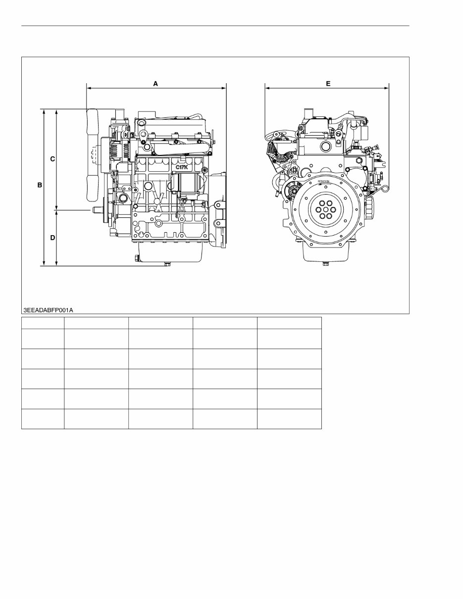
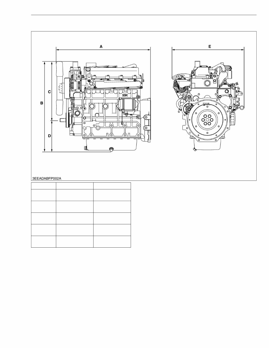
6 03-M-DI Series, WSM DIMENSIONS DIMENSIONS W1031045 D1503-M-DI D1503-M-DI-T D1703-M-DI D1803-M-DI A 599.2 mm (23.59 in.) 599.2 mm (23.59 in.) 572.1 mm (22.52 in.) 575.9 mm (22.67 in.) B 643.5 mm (25.33 in.) 644.0 mm (25.35 in.) 643.3 mm (25.33 in.) 685.0 mm (26.97 in.) C 414.2 mm (16.31 in.) 414.2 mm (16.31 in.) 414.0 mm (16.30 in.) 419.0 mm (16.50 in.) D 229.3 mm (9.03 in.) 229.8 mm (9.05 in.) 229.3 mm (9.03 in.) 266.0 mm (10.47 in.) E 514.4 mm (20.25 in.) 514.4 mm (20.25 in.) 507.1 mm (19.96 in.) 499.0 mm (19.65 in.) KiSC issued 10, 2009 A
7 DIMENSIONS 03-M-DI Series, WSM W1031355 V2203-M-DI V2403-M-DI A 667.1 mm (26.26 in.) 670.9 mm (26.41 in.) B 635.0 mm (25.00 in.) 684.5 mm (26.95 in.) C 414.0 mm (16.30 in.) 419.0 mm (16.50 in.) D 221.0 mm (8.70 in.) 265.5 mm (10.45 in.) E 507.1 mm (19.96 in.) 499.0 mm (19.65 in.) KiSC issued 10, 2009 A
CONTENTS MECHANISM 1. ENGINE BODY ............................................................................................... M-1 [1] HOLLOW CORE ....................................................................................... M-1 [2] PISTON ...................................................................................................... M-1 [3] BUILT-IN DYNAMIC BALANCER (BALANCER MODEL ONLY) ......... M-2 [4] HALF-FLOATING HEAD COVER ............................................................ M-2 2. COOLING SYSTEM ........................................................................................ M-3 [1] BOTTOM BYPASS SYSTEM................................................................... M-3 3. FUEL SYSTEM ............................................................................................... M-4 [1] GOVERNOR .............................................................................................. M-4 4. ELECTRICAL SYSTEM .................................................................................. M-6 [1] STARTER AUTO REDUCTION UNIT..................................................... M-6 (1) General ................................................................................................ M-6 (2) Basic Circuit ......................................................................................... M-6 (3) Component .......................................................................................... M-7 (4) Function ............................................................................................... M-7 KiSC issued 10, 2009 A
Kubota D1803-M-DI Engine Full Service Repair Manual is a comprehensive guide containing all the necessary information for repairing, maintaining, and restoring the Kubota D1803-M-DI Engine. It covers diagnostic and repair procedures in great detail, making it valuable for both professional technicians and do-it-yourself mechanics.
This manual includes detailed sub-steps that expand on repair procedure information, along with notes, cautions, and warnings throughout each chapter to pinpoint critical information. Numbered instructions and bold figure numbers help guide users through every repair procedure step by step. Additionally, detailed illustrations, drawings, and photos are provided to assist in the repair process.
Enlarged insets are included to help identify and examine parts in detail, and a numbered table of contents makes it easy to find the necessary information quickly. Troubleshooting and electrical service procedures are combined with detailed wiring diagrams for ease of use, making it convenient to diagnose and repair problems with the machine's electrical system.
The manual is available in .PDF format, which is compatible with all versions of Windows and Mac operating systems. It can be saved to a hard drive, burned to a CD-ROM, and printed if needed. This instant access eliminates the need for shipping and waiting for physical delivery.
The Kubota D1803-M-DI Engine Full Service Repair Manual covers a wide range of topics, including general information, specifications, engine removal, wiring diagrams, lubrication points, oil types, periodic maintenance, tune-up procedures, disassembly, reassembly, fuel and lubrication systems, electrical system, ignition, chassis, suspension, and much more.
With its comprehensive coverage and detailed instructions, this manual is an essential resource for anyone involved in the repair and maintenance of the Kubota D1803-M-DI Engine.
Recently Viewed
5,521,897Happy Clients
2,594,462eManuals
1,120,453Trusted Sellers
15Years in Business
Price:
Actual Price:
Kubota D1803-M-DI Engine Full Service Repair Manual