00-2 140-3 SERIES 4 CONTENTS No. of page 01 GENERAL ............................................................................................................................ 01-1 11 STRUCTURE AND FUNCTION, MAINTENANCE STANDARD............................................ 11-1 12 TESTING AND ADJUSTING ........................................................................ 12-1 13 DISASSEMBLY AND ASSEMBLY ...................................................... 13-1 15 REPAIR AND REPLACEMENT OF PARTS .................................................................................................. 15-1
140-3 SERIES 00-2-1 LIST OF REVISED PAGES (12) The affected pages are indicated by the use of the following marks. It is requested that necessary actions be taken to these pages according to the table below. Pages having no marks are those previously revised or made additions. LIST OF REVISED PAGES Mark Indication Action required Q Page to be newly added Add q Page to be replaced Replace ( ) Page to be deleted Discard Mark Page Time of revision Mark Page Time of revision Mark Page Time of revision Mark Page Time of revision Mark Page Time of revision q 00-1 (12) 01-3 11-1 11-26 11-57 00-2 (4) 01-4 11-2 11-27 11-58 q 00-2-1 (12) 01-6 (9) 11-3 11-28 11-59 q 00-2-2 (12) 01-7 (9) 11-4 11-29 11-60 q 00-2-3 (12) 01-8 (7) 11-5 11-30 11-61 00-3 q 01-9 (12) 11-6 (2) 11-32 11-62 00-4 01-10 (4) 11-7 (2) 11-33 11-63 00-5 01-20 (2) 11-8 (2) 11-34 (2) 11-64 00-6 01-21 (4) 11-9 (2) 11-35 11-65 00-7 01-22 (5) 11-9-1 (4) 11-36 11-66 00-8 01-23 (5) 11-9-2 (4) 11-37 11-67 00-9 01-24 (4) 11-9-3 (4) 11-38 11-68 00-10 01-25 (4) 11-9-4 (4) 11-39 11-69 00-11 q 01-26 (12) q 11-10 (12) 11-40 11-70 00-12 q 01-28 (12) 11-11 (9) 11-41 11-71 00-13 01-29 (4) 11-11-1 (7) 11-42 11-72 00-14 q 01-50 (12) 11-12 11-43 11-73 00-15 01-51 (4) 11-13 11-44 11-74 00-16 01-52 (9) 11-14 (10) 11-45 11-75 00-17 01-52-1 (9) 11-15 (10) 11-46 11-75-1 (8) 00-18 01-53 (4) 11-16 11-47 11-76 00-19 q 01-70 (12) 11-17 (2) 11-48 11-77 00-20 01-71 (7) 11-18 11-49 11-78 00-21 01-72 (5) 11-19 11-50 11-79 (2) 00-22 01-73 (5) 11-20 11-51 11-80 01-90 (5) 11-22 11-52 11-81 11-23 11-53 (11) q 11-82 (12) 01-1 (4) 11-24 11-54 11-83 (9) q 01-2 (12) 11-25 11-56 11-84 (9)
140-3 SERIES 00-2-3 LIST OF REVISED PAGES (12) Mark Page Time of revision Mark Page Time of revision Mark Page Time of revision Mark Page Time of revision Mark Page Time of revision 15-1 (4) 15-2 (4) 15-3 (4) 15-4 (4) 15-5 (4) 15-6 (4) 15-7 (4) 15-8 (4) 15-9 (4) 15-10 (4) 15-11 (4) 15-12 (4) 15-13 (4) 15-14 (4) 15-15 (4) 15-16 (4) 15-17 (4) 15-18 (4)
SAFETY SAFETY NOTICE 00-3 SAFETY SAFETY NOTICE IMPORTANT SAFETY NOTICE Proper service and repair is extremely important for safe machine operation. The service and repair techniques recommended by Komatsu and described in this manual are both effective and safe. Some of these techniques require the use of tools specially designed by Komatsu for the specific purpose. To prevent injury to workers, the symbol is used to mark safety precautions in this manual. The cautions accompanying these symbols should always be followed carefully. If any danger- ous situation arises or may possibly arise, first consider safety, and take the necessary actions to deal with the situation. GENERAL PRECAUTIONS Mistakes in operation are extremely dangerous. Read the Operation and Maintenance Manual care- fully BEFORE operating the machine. 1. Before carrying out any greasing or repairs, read all the precautions given on the decals which are fixed to the machine. 2. When carrying out any operation, always wear safety shoes and helmet. Do not wear loose work clothes, or clothes with buttons missing. • Always wear safety glasses when hitting parts with a hammer. • Always wear safety glasses when grinding parts with a grinder, etc. 3. If welding repairs are needed, always have a trained, experienced welder carry out the work. When carrying out welding work, always wear welding gloves, apron, hand shield, cap and other clothes suited for welding work. 4. When carrying out any operation with two or more workers, always agree on the operating procedure before starting. Always inform your fellow workers before starting any step of the operation. Before starting work, hang UNDER REPAIR signs on the controls in the operator's compartment. 5. Keep all tools in good condition and learn the correct way to use them. 6. Decide a place in the repair workshop to keep tools and removed parts. Always keep the tools and parts in their correct places. Always keep the work area clean and make sure that there is no dirt or oil on the floor. Smoke only in the areas provided for smoking. Never smoke while work- ing. PREPARATIONS FOR WORK 7. Before adding oil or making any repairs, park the machine on hard, level ground, and block the wheels or tracks to prevent the machine from moving. 8. Before starting work, lower blade, ripper, bucket or any other work equipment to the ground. If this is not possible, insert the safety pin or use blocks to prevent the work equipment from fall- ing. In addition, be sure to lock all the control levers and hang warning signs on them. 9. When disassembling or assembling, support the machine with blocks, jacks or stands before starting work. 10.Remove all mud and oil from the steps or other places used to get on and off the machine. Always use the handrails, ladders or steps when getting on or off the machine. Never jump on or off the machine. If it is impossible to use the handrails, ladders or steps, use a stand to pro- vide safe footing.
SAFETY SAFETY NOTICE 00-4 PRECAUTIONS DURING WORK 11.When removing the oil filler cap, drain plug or hydraulic pressure measuring plugs, loosen them slowly to prevent the oil from spurting out. Before disconnecting or removing components of the oil, water or air circuits, first remove the pressure completely from the circuit. 12.The water and oil in the circuits are hot when the engine is stopped, so be careful not to get burned. Wait for the oil and water to cool before carry- ing out any work on the oil or water circuits. 13.Before starting work, remove the leads from the battery. Always remove the lead from the nega- tive (–) terminal first. 14.When raising heavy components, use a hoist or crane. Check that the wire rope, chains and hooks are free from damage. Always use lifting equipment which has ample capacity. Install the lifting equipment at the correct places. Use a hoist or crane and operate slowly to pre- vent the component from hitting any other part. Do not work with any part still raised by the hoist or crane. 15.When removing covers which are under internal pressure or under pressure from a spring, always leave two bolts in position on opposite sides. Slowly release the pressure, then slowly loosen the bolts to remove. 16.When removing components, be careful not to break or damage the wiring. Damaged wiring may cause electrical fires. 17.When removing piping, stop the fuel or oil from spilling out. If any fuel or oil drips onto the floor, wipe it up immediately. Fuel or oil on the floor can cause you to slip, or can even start fires. 18.As a general rule, do not use gasoline to wash parts. In particular, use only the minimum of gasoline when washing electrical parts. 19.Be sure to assemble all parts again in their origi- nal places. Replace any damaged parts with new parts. • When installing hoses and wires, be sure that they will not be damaged by contact with other parts when the machine is being operated. 20.When installing high pressure hoses, make sure that they are not twisted. Damaged tubes are dangerous, so be extremely careful when install- ing tubes for high pressure circuits. Also, check that connecting parts are correctly installed. 21.When assembling or installing parts, always use the specified tightening torques. When installing protective parts such as guards, or parts which vibrate violently or rotate at high speed, be par- ticularly careful to check that they are installed correctly. 22.When aligning two holes, never insert your fin- gers or hand. Be careful not to get your fingers caught in a hole. 23.When measuring hydraulic pressure, check that the measuring tool is correctly assembled before taking any measurements. 24.Take care when removing or installing the tracks of track-type machines. When removing the track, the track separates suddenly, so never let anyone stand at either end of the track.
FOREWORD GENERAL 00-5 FOREWORD GENERAL This shop manual has been prepared as an aid to improve the quality of repairs by giving the serviceman an accurate understanding of the product and by showing him the correct way to perform repairs and make judge- ments. Make sure you understand the contents of this manual and use it to full effect at every opportunity. This shop manual mainly contains the necessary technical information for operations performed in a service workshop. For ease of understanding, the manual is divided into the following chapters; these chapters are fur- ther divided into the each main group of components. STRUCTURE AND FUNCTION This section explains the structure and function of each component. It serves not only to give an under- standing of the structure, but also serves as reference material for troubleshooting. In addition, this section may contain hydraulic circuit diagrams, electric circuit diagrams, and mainte- nance standards. TESTING AND ADJUSTING This section explains checks to be made before and after performing repairs, as well as adjustments to be made at completion of the checks and repairs. Troubleshooting charts correlating "Problems" with "Causes" are also included in this section. DISASSEMBLY AND ASSEMBLY This section explains the procedures for removing, installing, disassembling and assembling each com- ponent, as well as precautions for them. MAINTENANCE STANDARD This section gives the judgment standards for inspection of disassembled parts. The contents of this section may be described in STRUCTURE AND FUNCTION. OTHERS This section mainly gives hydraulic circuit diagrams and electric circuit diagrams. In addition, this section may give the specifications of attachments and options together. NOTICE The specifications contained in this shop manual are subject to change at any time and without any advance notice. Use the specifications given in the book with the latest date.
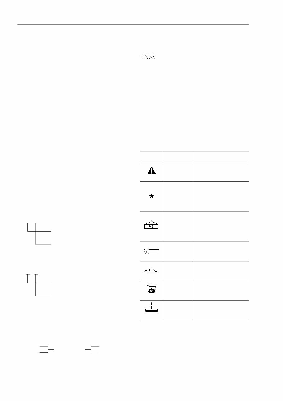
FOREWORD HOW TO READ THE SHOP MANUAL 00-6 HOW TO READ THE SHOP MANUAL VOLUMES Shop manuals are issued as a guide to carrying out repairs. They are divided as follows: Chassis volume: Issued for every machine model Engine volume: Issued for each engine series Electrical volume: Attachments volume: These various volumes are designed to avoid dupli- cating the same information. Therefore, to deal with all repairs for any model , it is necessary that chas- sis, engine, electrical and attachment volumes be available. DISTRIBUTION AND UPDATING Any additions, amendments or other changes will be sent to KOMATSU distributors. Get the most up-to- date information before you start any work. FILING METHOD 1. See the page number on the bottom of the page. File the pages in correct order. 2. Following examples show how to read the page number. Example 1 (Chassis volume): 10 - 3 Item number (10. Structure and Function) Consecutive page number for each item. Example 2 (Engine volume): 12 - 5 Unit number (1. Engine) Item number (2. Testing and Adjust- ing) Consecutive page number for each item. 3. Additional pages: Additional pages are indicated by a hyphen (-) and number after the page number. File as in the example. Example: 10-4 10-4-1 10-4-2 10-5 REVISED EDITION MARK When a manual is revised, an edition mark ( ....) is recorded on the bottom of the pages. REVISIONS Revised pages are shown in the LIST OF REVISED PAGES next to the CONTENTS page. SYMBOLS So that the shop manual can be of ample practical use, important safety and quality portions are marked with the following symbols. Symbol Item Remarks Safety Special safety precautions are necessary when per- forming the work. Caution Special technical precau- tions or other precautions for preserving standards are necessary when per- forming the work. Weight Weight of parts of sys- tems. Caution necessary when selecting hoisting wire, or when working pos- ture is important, etc. Tightening torque Places that require special attention for the tightening torque during assembly. Coat Places to be coated with adhesives and lubricants, etc. Oil, water Places where oil, water or fuel must be added, and the capacity. Drain Places where oil or water must be drained, and quantity to be drained. }· Each issued as one volume to cover all models 12-203 12-203-1 12-203-2 12-204 Added pages
This workshop service manual for the Komatsu SA6D140E-3 Diesel Engine is designed for mechanical technicians familiar with service procedures for BRP products. It covers repair and overhaul procedures, including instructions on components manufactured for the engine. The manual also provides information and procedures for routine maintenance, servicing, and diagnostic and repair procedures. It is useful for both professional mechanics and DIY enthusiasts.
For those intending to do maintenance and repair on their Komatsu SA6D140E-3 Diesel Engine, it is essential that safety equipment be used and safety precautions observed when working on the engine. This includes using a torque wrench to ensure that fasteners are tightened in accordance with specifications. In some cases, the text refers to special tools that are recommended or required to accomplish adjustments or repairs. These tools are often identified by their Komatsu SA6D140E-3 Diesel Engine special tool number and illustrated.
The manual contains specifications and procedures available in an authorized Komatsu SA6D140E-3 Diesel Engine dealer service department. It emphasizes particular information denoted by the wording and symbols: WARNING, CAUTION, NOTE. The aim of this manual is to help you get the best value from your Komatsu SA6D140E-3 Diesel Engine.
This is a .PDF manual and does not include interactive features. It is a complete service manual containing all necessary instructions needed for any repair your Komatsu SA6D140E-3 Diesel Engine may require. The content depicts parts and/or procedures applicable to the particular product at the time of writing.
Tune ups for Komatsu SA6D140E-3 Diesel Engine
Maintenance for Komatsu SA6D140E-3 Diesel Engine
Removal & install procedures for Komatsu SA6D140E-3 Diesel Engine
Assemblies & disassemblies for Komatsu SA6D140E-3 Diesel Engine
Fuel system for Komatsu SA6D140E-3 Diesel Engine
Ignition for Komatsu SA6D140E-3 Diesel Engine
Lubrication system for Komatsu SA6D140E-3 Diesel Engine
Exhaust for Komatsu SA6D140E-3 Diesel Engine
Electrical system for Komatsu SA6D140E-3 Diesel Engine
Body for Komatsu SA6D140E-3 Diesel Engine
More extensive repair involving ENGINE and TRANSMISSION disassembly for Komatsu SA6D140E-3 Diesel Engine
Specification:
This is a FORM NOT A HARD COPY!!!
FAST and FREE ELECTRONIC DELIVERY via Email!!!
Language: English
Printable: Yes
File Format: .PDF
General maintenance tags for WSMBEST workshop service manuals:
Air cleaner element renewal for Komatsu SA6D140E-3 Diesel Engine
Battery electrolyte level check for Komatsu SA6D140E-3 Diesel Engine
Brake hydraulic fluid renewal for Komatsu SA6D140E-3 Diesel Engine
Engine coolant renewal for Komatsu SA6D140E-3 Diesel Engine
Engine oil and filter renewal for Komatsu SA6D140E-3 Diesel Engine
Exhaust system check for Komatsu SA6D140E-3 Diesel Engine
Fluid leak check for Komatsu SA6D140E-3 Diesel Engine
Front and rear brake pad/shoe check for Komatsu SA6D140E-3 Diesel Engine
Front wheel alignment check for Komatsu SA6D140E-3 Diesel Engine
Gearbox oil level check for Komatsu SA6D140E-3 Diesel Engine
Intensive maintenance for Komatsu SA6D140E-3 Diesel Engine
Road test for Komatsu SA6D140E-3 Diesel Engine
Wiper blade check for Komatsu SA6D140E-3 Diesel Engine
Komatsu SA6D140E-3 Diesel Engine Workshop Service Manual.
Recently Viewed
5,521,897Happy Clients
2,594,462eManuals
1,120,453Trusted Sellers
15Years in Business
Price:
Actual Price:
Komatsu SA6D140E-3 Diesel Engine Repair Service Manual