COMMAND SERVICE MANUAL VERTICAL CRANKSHAFT CV11-16, CV460-465, CV490-495
Contents Section 1. Safety and General Information ............................................................................ Section 2. Special Tools .......................................................................................................... Section 3. Troubleshooting ..................................................................................................... Section 4. Air Cleaner and Air Intake System ........................................................................ Section 5. Fuel System and Governor .................................................................................... Section 6. Lubrication System ................................................................................................ Section 7. Retractable Starter ................................................................................................. Section 8. Electrical System and Components ..................................................................... Section 9. Disassembly ........................................................................................................... Section 10. Inspection and Reconditioning ........................................................................... Section 11. Reassembly ........................................................................................................... 1 2 3 4 5 6 7 8 9 10 11
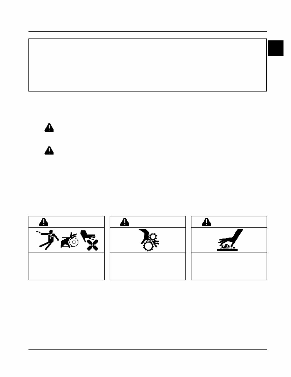
1.1 1 Section 1 Safety and General Information CV11-16 CV460-465, CV490-495 Safety Precautions To insure safe operations please read the following statements and understand their meaning. Also refer to your equipment manufacturer's manual for other important safety information. This manual contains safety precautions which are explained below. Please read carefully. WARNING Warning is used to indicate the presence of a hazard that can cause severe personal injury, death, or substantial property damage if the warning is ignored. CAUTION Caution is used to indicate the presence of a hazard that will or can cause minor personal injury or property damage if the caution is ignored. NOTE Note is used to notify people of installation, operation, or maintenance information that is important but not hazard-related. For Your Safety! These precautions should be followed at all times. Failure to follow these precautions could result in injury to yourself and others. Rotating Parts can cause severe injury. Stay away while engine is in operation. WARNING Rotating Parts! Keep hands, feet, hair, and clothing away from all moving parts to prevent injury. Never operate the engine with covers, shrouds, or guards removed. Hot Parts can cause severe burns. Do not touch engine while operating or just after stopping. WARNING Hot Parts! Engine components can get extremely hot from operation. To prevent severe burns, do not touch these areas while the engine is running—or immediately after it is turned off. Never operate the engine with heat shields or guards removed. Accidental Starts can cause severe injury or death. Disconnect and ground spark plug leads before servicing. WARNING Accidental Starts! Disabling engine. Accidental starting can cause severe injury or death. Before working on the engine or equipment, disable the engine as follows: 1) Disconnect the spark plug lead(s). 2) Disconnect negative (-) battery cable from battery.
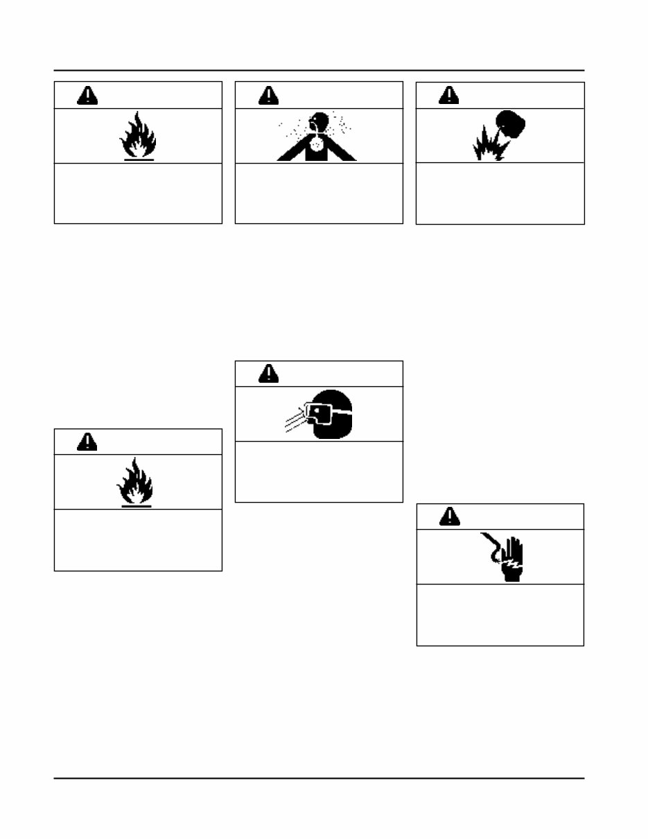
1.2 Section 1 Safety and General Information Carbon Monoxide can cause severe nausea, fainting or death. Do not operate engine in closed or confined area. WARNING Electrical Shock can cause injury. Do not touch wires while engine is running. CAUTION Uncoiling Spring can cause severe injury. Wear safety goggles or face protection when servicing retractable starter. WARNING Lethal Exhaust Gases! Engine exhaust gases contain poisonous carbon monoxide. Carbon monoxide is odorless, colorless, and can cause death if inhaled. Avoid inhaling exhaust fumes, and never run the engine in a closed building or confined area. Spring Under Tension! Retractable starters contain a powerful, recoil spring that is under tension. Always wear safety goggles when servicing retractable starters and carefully follow instructions in "Retractable Starter" Section 7 for relieving spring tension. Explosive Gas! Batteries produce explosive hydrogen gas while being charged. To prevent a fire or explosion, charge batteries only in well ventilated areas. Keep sparks, open flames, and other sources of ignition away from the battery at all times. Keep batteries out of the reach of children. Remove all jewelry when servicing batteries. Before disconnecting the negative (-) ground cable, make sure all switches are OFF. If ON, a spark will occur at the ground cable terminal which could cause an explosion if hydrogen gas or gasoline vapors are present. Electrical Shock! Never touch electrical wires or components while the engine is running. They can be sources of electrical shock. Explosive Fuel can cause fires and severe burns. Stop engine before filling fuel tank. WARNING Explosive Fuel! Gasoline is extremely flammable and its vapors can explode if ignited. Store gasoline only in approved containers, in well ventilated, unoccupied buildings, away from sparks or flames. Do not fill the fuel tank while the engine is hot or running, since spilled fuel could ignite if it comes in contact with hot parts or sparks from ignition. Do not start the engine near spilled fuel. Never use gasoline as a cleaning agent. Cleaning Solvents can cause severe injury or death. Use only in well ventilated areas away from ignition sources. WARNING Flammable Solvents! Carburetor cleaners and solvents are extremely flammable. Keep sparks, flames, and other sources of ignition away from the area. Follow the cleaner manufacturer’s warnings and instructions on its proper and safe use. Never use gasoline as a cleaning agent. WARNING Explosive Gas can cause fires and severe acid burns. Charge battery only in a well ventilated area. Keep sources of ignition away.
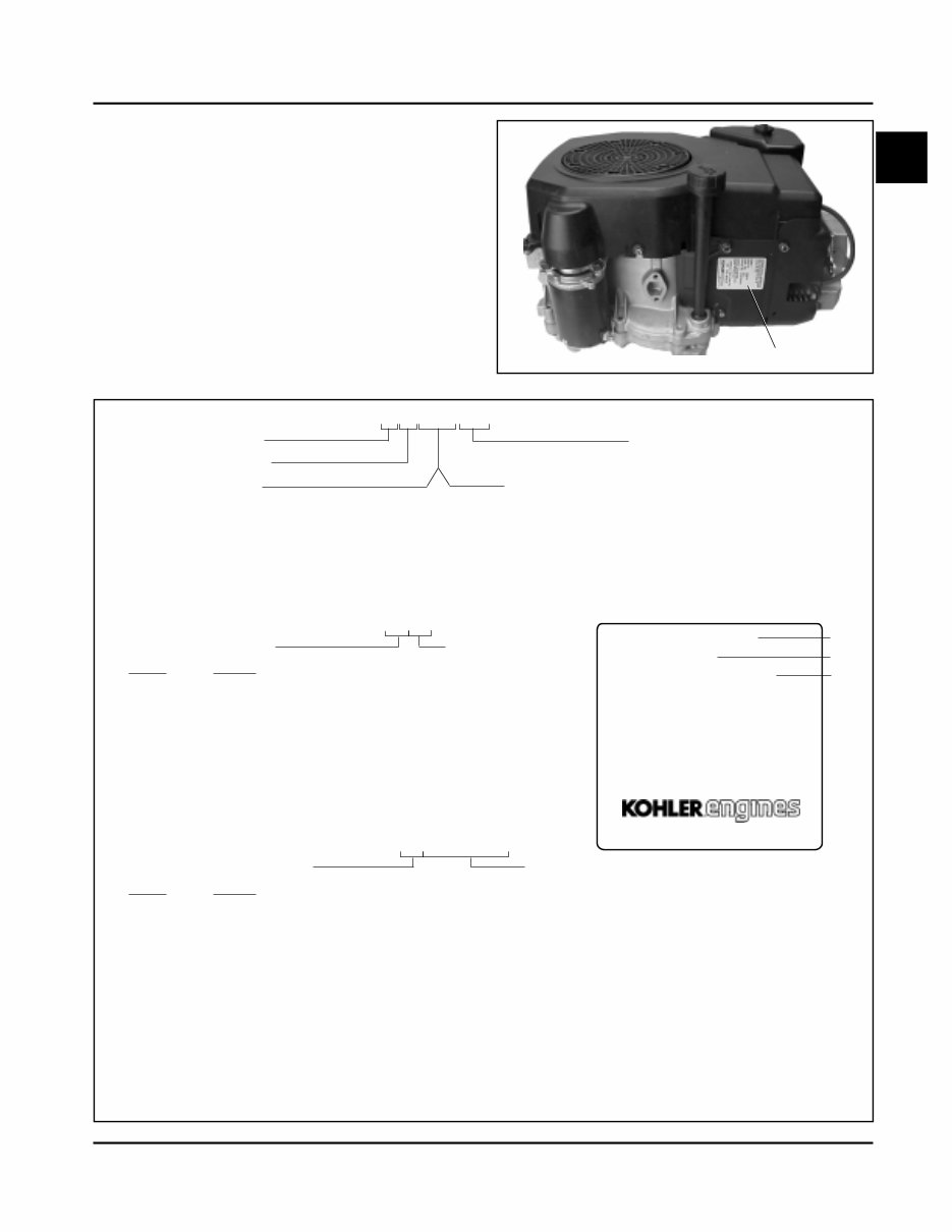
1.3 Section 1 Safety and General Information 1 A. Model No. Command Engine Vertical Crankshaft Displacement (cc) 460 = 460 cc 490 = 490 cc Version Code S = Electric Start T = Retractable Start ST = Electric/Retractable Start Variation of Basic Engine B. Spec. No. Engine Model Code Code Model 11 CV11 12 CV12.5 22 CV13 14 CV14 41 CV15 43 CV16 265 CV460-465 275 CV490-495 C. Serial No. Year Manufactured Code Code Model 21 1991 22 1992 23 1993 24 1994 25 1995 26 1996 27 1997 28 1998 29 1999 30 2000 31 2001 32 2002 Factory Code 2105810334 Engine Identification Numbers When ordering parts, or in any communication involving an engine, always give the Model, Specification, and Serial Numbers of the engine. The engine identification numbers appear a on decal (or decals) affixed to the engine shrouding. See Figure 1-1. An explanation of these numbers is shown in Figure 1-2. Figure 1-2. Explanation of Engine Identification Numbers. C V 12.5 ST 1203 Figure 1-1. Engine Identification Decal Location. or Horsepower 11 = 11 HP 12.5 = 12.5 HP 13 = 13 HP 14 = 14 HP 15 = 15 HP 16 = 16 HP Identification Decal MODEL NO. SPEC. NO. SERIAL NO. REFER TO OWNER'S MANUAL FOR SAFETY, MAINTENANCE SPECS AND ADJUSTMENTS. FOR SALES AND SERVICE IN US/CANADA CALL: 1-800-544-2444. www.kohlerengines.com KOHLER CO. KOHLER, WI USA CV12.5ST 1203 2105810334 A B C
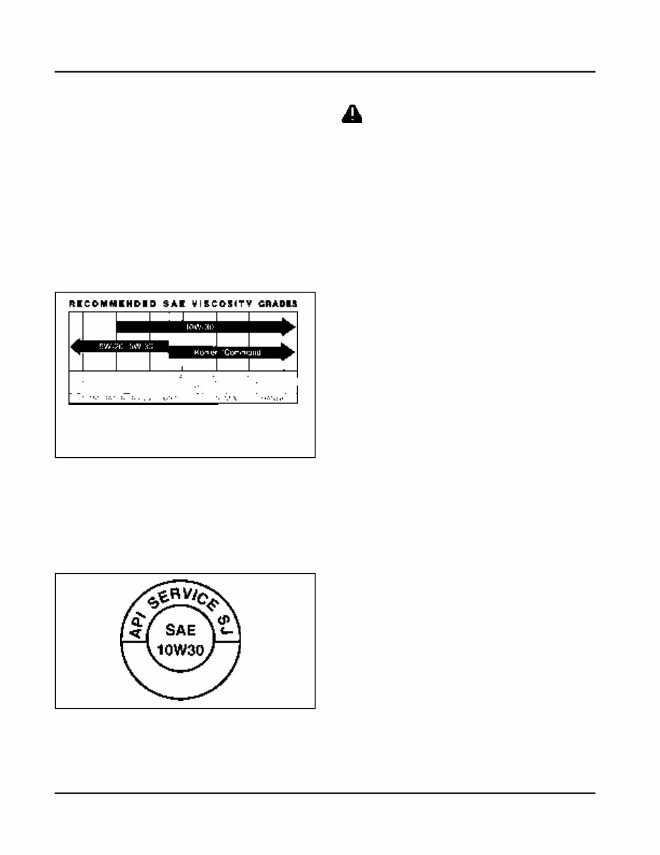
1.4 Section 1 Safety and General Information Oil Recommendations Using the proper type and weight of oil in the crankcase is extremely important, as is checking oil daily, and changing oil regularly. Failure to use the correct oil, or using dirty oil, causes premature engine wear and failure. Synthetic oil is recommended for use in LPG-fueled engines because there is less oxidation or thickening, and deposit accumulation on intake valves is substantially reduced. Oil Type Use high-quality detergent oil of API (American Petroleum Institute) service class SG, SH, SJ or higher. Select the viscosity based on the air temperature at the time of operation as shown below. NOTE: Using other than service class SG, SH, SJ or higher oil, or extending oil change intervals longer than recommended, can cause engine damage. A logo or symbol on oil containers identifies the API service class and SAE viscosity grade. See Figure 1-3. Fuel Recommendations WARNING: Explosive Fuel! Gasoline is extremely flammable and its vapors can explode if ignited. Store gasoline only in approved containers, in well ventilated, unoccupied buildings, away from sparks or flames. Do not fill the fuel tank while the engine is hot or running, since spilled fuel could ignite if it comes in contact with hot parts or sparks from ignition. Do not start the engine near spilled fuel. Never use gasoline as a cleaning agent. General Recommendations Purchase gasoline in small quantities and store in clean, approved containers. A container with a capacity of 2 gallons or less with a pouring spout is recommended. Such a container is easier to handle and helps eliminate spillage during refueling. Do not use gasoline left over from the previous season, to minimize gum deposits in your fuel system and to insure easy starting. Do not add oil to the gasoline. Do not overfill the fuel tank. Leave room for the fuel to expand. Fuel Type For best results, use only clean, fresh, unleaded gasoline with a pump sticker octane rating of 87 or higher. In countries using the Research method, it should be 90 octane minimum. Unleaded gasoline is recommended, as it leaves less combustion chamber deposits. Leaded gasoline may be used in areas where unleaded is not available and exhaust emissions are not regulated. Be aware however, that the cylinder head will require more frequent service. Gasoline/Alcohol blends Gasohol (up to 10% ethyl alcohol, 90% unleaded gasoline by volume) is approved as a fuel for Kohler engines. Other gasoline/alcohol blends are not approved. Gasoline/Ether blends Methyl Tertiary Butyl Ether (MTBE) and unleaded gasoline blends (up to maximum of 15% MTBE by volume) are approved as a fuel for Kohler engines. Other gasoline/ether blends are not approved. Figure 1-3. Oil Container Logo. Refer to Section 6 - “Lubrication System” for detailed oil check, oil change, and oil filter change procedures. *Use of synthetic oil having 5W-20 or 5W-30 rating is acceptable, up to 4°C (40°F). **Synthetic oils will provide better starting in extreme cold below -23°C (-10°F). ** *
1.5 Section 1 Safety and General Information 1 Periodic Maintenance WARNING: Accidental Starts! Disabling engine. Accidental starting can cause severe injury or death. Before working on the engine or equipment, disable the engine as follows: 1) Disconnect the spark plug lead(s). 2) Disconnect negative (-) battery cable from battery. Maintenance Schedule These required maintenance procedures should be performed at the frequency stated in the table. They should also be included as part of any seasonal tune-up. Storage If the engine will be out of service for two months or more, use the following storage procedure. 1. Clean the exterior surfaces of the engine. 2. Change the oil and oil filter while the engine is still warm from operation. See “Change Oil and Oil Filter” in Section 6. 3. The fuel system must be completely emptied, or the gasoline must be treated with a stabilizer to prevent deterioration. If you choose to use a stabilizer, follow the manufacturers recommendations, and add the correct amount for the capacity of the fuel system. Fill the fuel tank with clean, fresh gasoline. Run the engine for 2-3 minutes to get stabilized fuel into the carburetor. To empty the system, run the engine until the tank and system are empty. 4. Remove the spark plug. Add one tablespoon of engine oil into the spark plug hole. Install the plug, but do not connect the plug lead. Crank the engine two or three revolutions. 5. Remove the spark plug. Cover the spark plug hole with your thumb, and turn the engine over until the piston is at the top of its stroke. (Pressure against thumb is greatest.) Reinstall the plug, but do not connect the plug lead. 6. Store the engine in a clean, dry place. Frequency Maintenance Required Refer to: • Fill fuel tank. • Check oil level. • Check air cleaner for dirty 1 , loose, or damaged parts. • Check air intake and cooling areas, clean as necessary 1 . Daily or Before Starting Engine Section 5 Section 6 Section 4 Section 4 • Service precleaner element 1 . Every 25 Hours Section 4 • Replace air cleaner element 1 . • Change oil 1 . • Remove cooling shrouds and clean cooling areas 1 . Every 100 Hours Section 4 Section 6 Section 4 • Change oil filter 1 . • Check spark plug condition and gap. Every 200 Hours Section 6 Section 8 1 Perform these maintenance procedures more frequently under extremely dusty, dirty conditions. 2 Have a Kohler Engine Service Dealer perform this service. Not necessary on Delco Starters. Annually or Every 500 Hours • Have bendix starter drive serviced 2 . • Have solenoid shift starter disassembled and cleaned 2 . Section 8 Section 8
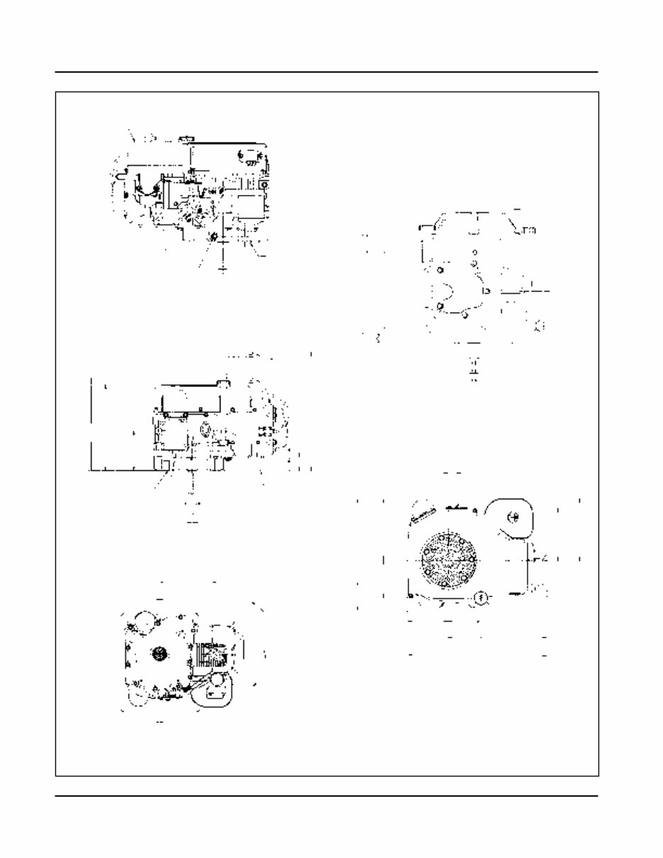
1.6 Section 1 Safety and General Information Figure 1-4. Typical Engine Dimensions. Air Filter and Cover Cylinder Carburetor Fuel Shut-off Solenoid Carburetor Fuel Inlet Oil Drain Plug 3/8 NPT Inch Oil Filter Side 17 (.67) Engine Mounting Surface Oil Filter Cylinder 262 (10.31) 47 (1.85) 24.0 (9.4) Valve Cover End 25.4 (1.00) 6.34 (.250) Keyway Width 220.2 (8.67) 45° 45° 60.0 (2.36) 4.0 (.16) 40° M8x1.25 2 Studs Exhaust Flange Mounting Surface Engine Mounting Surface 35° 35° Rotation 254 (10.0) Cylinder 4xM8x1.25 296 (11.65) 321 (12.64) Cylinder 137.5 (5.41) 411 (16.18) Air Cleaner Cover Removal 62.5 (2.46) 19 (.74) Exhaust Flange Mounting Surface 25.4 (1.00) 6.34 (.250) Keyway Width Starter Side Starter Motor Engine Mounting Surface 26.5 (1.04) Throttle Cable 207 (80.16) 176.6 (6.95) Oil Level Dipstick & Fill 328* (12.91) 463* (18.23) 108 (4.25) 135.0 (5.31) Flywheel End 372 (14.66) 204 (8.04) 124 (4.88) Dimensions in () are inch equivalents. *CV11-16 10 mm shorter C L C L C L Cylinder C L C L C L
1.7 Section 1 Safety and General Information 1 General Specifications¹ Power (@ 3600 RPM, corrected to SAE J1995) CV11 ............................................................................... 8.2 kW (11 HP) CV12.5 ............................................................................ 9.33 kW (12.5 HP) CV13 ............................................................................... 9.75 kW (13 HP) CV14 ............................................................................... 10.5 kW (14 HP) CV15 ............................................................................... 11.19 kW (15 HP) CV16 ............................................................................... 11.9 kW (16 HP) CV460-465 ...................................................................... 11.9 kW (16 HP)-13.0 kW (16.5 HP) CV490-495 ...................................................................... 12.7 kW (17 HP)-13.4 kW (18 HP) Max Torque (@ RPM indicated) CV11 ................................................................................ 27.4 N·m (20.2 ft. lb.) @ 2000 CV12.5 ............................................................................. 27.8 N·m (20.5 ft. lb.) @ 2500 CV13 ................................................................................ 27.8 N·m (20.5 ft. lb.) @ 2500 CV14 ................................................................................ 28.9 N·m (21.3 ft. lb.) @ 2500 CV15 ................................................................................ 33.2 N·m (24.5 ft. lb.) @ 2400 CV16 ................................................................................ 35.3 N·m (26.0 ft. lb.) @ 2400 CV460-465 ....................................................................... 36.3 N·m (26.8 ft. lb.) @ 2400 CV490-495 ....................................................................... 37.8 N·m (27.9 ft. lb.)-38.1 N·m (28.1 ft. lb.) @ 2400 Bore CV11-14, CV460-465 ........................................................ 87 mm (3.43 in.) CV15, CV16, CV490-495 .................................................. 90 mm (3.60 in.) Stroke CV11-16 .......................................................................... 67 mm (2.64 in.) CV460-465, CV490-495 .................................................. 77 mm (3.03 in.) Displacement CV11-14 ............................................................................ 398 cc (24.3 cu. in. 3 ) CV15, CV16 ...................................................................... 426 cc (26.0 cu. in. 3 ) CV460-465 ........................................................................ 460 cc (27.9 cu. in. 3 ) CV490-495 ........................................................................ 490 cc (29.9 cu. in. 3 ) Compression Ratio .................................................................. 8.5:1 Weight (approx.) CV11-16 ............................................................................ 39.54 kg (87 lb.) CV460-465, CV490-495 .................................................... 41.9 kg (90 lb.) Oil Capacity (approx.) .............................................................. 1.9 L (2.0 U.S. qt.) Air Cleaner Base Nut Torque ...................................................................... 9.9 N·m (88 in. lb.) Wing Nut Torque ...................................................................... 1.5 N·m (12 in. lb.) Angle of Operation - Maximum (at full oil level) Intermittent - All Directions ....................................................... 35° Continuous - All Directions ....................................................... 20° 1 Values are in Metric units. Values in parentheses are English equivalents. Lubricate threads with engine oil prior to assembly.
1.8 Section 1 Safety and General Information Balance Shaft End Play ...................................................................................................... 0.0575/0.3625 mm (0.0027/0.0137 in.) Running Clearance ...................................................................................... 0.0250/0.1520 mm (0.0009/0.0059 in.) Bore I.D. New ....................................................................................................... 20.000/20.025 mm (0.7874/0.7884 in.) Max. Wear Limit .................................................................................... 20.038 mm (0.7889 in.) Balance Shaft Bearing Surface O.D. New ....................................................................................................... 19.962/19.975 mm (0.7859/0.7864 in.) Max. Wear Limit .................................................................................... 19.959 mm (0.7858 in.) Camshaft End Play (free) ............................................................................................. 0.088/0.393 mm (0.003/0.015 in.) End Play (with shims) .................................................................................. 0.076/0.127 mm (0.003/0.005 in.) Running Clearance ...................................................................................... 0.025/0.105 mm (0.0010/0.0041 in.) Bore I.D. New ....................................................................................................... 20.000/20.025 mm (0.7874/0.7884 in.) Max. Wear Limit .................................................................................... 20.038 mm (0.7889 in.) Camshaft Bearing Surface O.D. New ...................................................................................................... 19.962/19.975 mm (0.7859/0.7864 in.) Max. Wear Limit ................................................................................... 19.959 mm (0.7858 in.) Carburetor Preliminary Low Idle Fuel Needle Setting ................................................... 1 Turn Fuel Bowl Retaining Screw Torque ............................................................. 5.1-6.2 N·m (45-55 in. lb.) Connecting Rod Cap Fastener Torque (torque in increments) 6 mm straight shank bolt ....................................................................... 11.3 N·m (100 in. lb.) 8 mm step-down bolt ............................................................................. 14.7 N·m (130 in. lb.) 8 mm straight shank bolt ....................................................................... 22.7 N·m (200 in. lb.) Connecting Rod-to-Crankpin Running Clearance at 21°C (70°F) New ....................................................................................................... 0.030/0.055 mm (0.0012/0.0022 in.) Max. Wear Limit .................................................................................... 0.07 mm (0.0025 in.) Connecting Rod-to-Crankpin Side Clearance .............................................. 0.18/0.41 mm (0.007/0.016 in.) Connecting Rod-to-Piston Pin Running Clearance at 21°C (70°F) .............. 0.015/0.028 mm (0.0006/0.0011 in.) Piston Pin End I.D. New ...................................................................................................... 19.015/19.023 mm (0.7486/0.7489 in.) Max. Wear Limit ................................................................................... 19.036 mm (0.7495 in.) Crankcase Governor Cross Shaft Bore I.D. New ...................................................................................................... 6.025/6.050 mm (0.2372/0.2382 in.) Max. Wear Limit ................................................................................... 6.063 mm (0.2387 in.)
The Kohler CV490 Engine Full Service Repair Manual is a comprehensive guide that contains all the necessary information for repairing, maintaining, rebuilding, refurbishing, or restoring your Kohler CV490 Engine. It covers diagnostic and repair procedures in great detail, making it an essential resource for both professional technicians and do-it-yourself mechanics.
This manual is a series of practical repair and service manuals used by mechanics worldwide. It includes repair procedures, service schedules, maintenance, wiring diagrams, and diagnostics. The detailed sub-steps expand on repair procedure information, and notes, cautions, and warnings throughout each chapter pinpoint critical information. Numbered instructions and bold figure numbers help you navigate through every repair procedure step by step. Additionally, detailed illustrations, drawings, and photos guide you through each process, with an enlarged inset to help you identify and examine parts in detail.
The manual also includes a numbered table of contents for easy navigation, troubleshooting, and electrical service procedures combined with detailed wiring diagrams for ease of use. It is available in .PDF format, making it compatible with all versions of Windows and Mac. The full printable format allows for easy access and can be saved to your hard drive or burned to a CD-ROM. This means no shipping costs or waiting for the book or CD to arrive in the mail.
The Kohler CV490 Engine Full Service Repair Manual covers a wide range of topics, including general information, specifications, engine removal, wiring diagrams, lubrication points, oil types, periodic maintenance, tune-up procedures, disassembly, reassembly, fuel and lubrication systems, electrical system, ignition, chassis, suspension, servicing information, service data, tools, tightening torques, gearbox, exhaust system, clutch removal and installation, transmission, bodywork, cooling system, electrics, and much more.
Overall, the Kohler CV490 Engine Full Service Repair Manual is an invaluable resource for anyone looking to maintain or repair their Kohler CV490 Engine, providing comprehensive and detailed information for professional technicians and do-it-yourself mechanics alike.