Safety Precautions To insure safe operations please read the following statements and understand their meaning. Also refer to your equipment owner's manual for other important safety information. This manual contains safety precautions which are explained below. Please read carefully. a WARNING Warning is used to indicate the presence of a hazard that can cause severe personal injury, death, or substantial property damage if the warning is ignored. a CAUTION Caution is used to indicate the presence of a hazard that will or can cause minor personal injury or property damage if the caution is ignored. NOTE Note is used to notify people of installation, operation, or maintenance information that is important but not hazard-related. For Your Safety! These precautions should be followed at all times. Failure to follow these precautions could result in injury to yourself and others. I a WARNING Explosive Fuel can cause fires and severe burns. Stop engine before filling fuel tank. Explosive Fuel! Gasoline is extremely flammable and its vapors can explode if ignited. Store gasoline only in approved containers, in well ventilated, unoccupied buildings, away from sparks or flames. Do not fill the fuel tank while the engine is hot or running, since spilled fuel could ignite if it comes in contact with hot parts or sparks from ignition. Do not start the engine near spilled fuel. Never use gasoline as a cleaning agent. a WARNING Rotating Parts can cause severe injury. Stay away while engine is in operation. Rotating Parts! Keep hands, feet, hair, and clothing a way from all moving parts to prevent injuty Never operate the engine with covers, shrouds, or guards removed. a CAUTION Yll 1 Electrical Shock can cause injury. Do not touch wires while engine is running. I a WARNING I Hot Parts can cause severe burns. Do not touch engine while operating or just after stopping. Hot Parts! Engine components can get extremely hot from operation. To prevent severe burns, do not touch these areas while the engine is running, or immediately after it is turned off. Never operate the engine with heat shields or guards removed. California Proposition 65 Warning Engine exhaust from this product contains chemicals known to the State of California to cause cancer, birth defects, or other reproductive harm. Electrical Shock! Never touch electrical wires or components while the engine is running. They can be sources of electrical shock. 2
Safefy Precautions (Conf.) WARNING Accidental Starts can cause severe injury or death. Disconnect and ground spark plug leads before sewicing. Accidental Starts! Disabing engine. Accidents/ staring can cause severe injuv or death. Before working on the engine or equipment, disable the engine as follows: 1) Disconnect the spark plug lead(s). 2) Disconnect negative (-) battery cable from battery. a WARNING Carbon Monoxide can cause severe nausea, fainting or death. Do not operate engine in closed or confined area. \. -6 I Explosive Gas can cause fires and severe acid burns. Charge battey only in a well ventilated area. Keep sources of ianition awav. Lethal Exhaust Gases! Engine exhaust gases contain poisonous carbon monoxide. Carbon monoxide is odorless, colorless, and can cause death if inhaled. Avoid inhaling exhaust Explosive Gas! Batteries produce explosive hydrogen gas while being charged. To prevent a fire or explosion, charge batteries only in well ventilated areas. Keep sparks, open fumes, and never run-the engine in a closed building or confined area. flames, and other sources of ignition away from the battery at all times. Keep batteries out of the reach of children. Remove all jewelry when servicing batteries. ' Before disconnecting the negative (-) ground cable, make sure all switches are OFF: If ON, a spark will occur at the ground cable terminal which could cause an explosion if hydrogen gas or gasoline vapors are present. Congratulations -You have selected a fine four-cycle, twin cylinder, air-cooled engine. Kohler designs long life strength and on-the-job durability into each engine ... making a Kohler engine dependable ... dependability you can count on. Here are some reasons why: Efficient overhead valve design and full pressure lubrication provide maximum power, torque, and reliability under all operating conditions. Dependable, maintenance-free electronic ignition ensures fast, easy starts time after time. Kohler engines are easy to service. All routine service areas like the dipstick, oil fill, air cleaner, and spark plugs are easily and quickly accessible. Parts subject to the most wear and tear (like the cylinder liner* and camshaft) are made from precision formulated cast iron. Because the cylinder liner* can be rebored, these engines can last even longer. *Some CH25/26 engines have POWER-BORETM Cylinders. These cylinders are plated with nickel-silicon to give increased power, virtually permanent cylinder life, superior oil control, and reduced exhaust emissions. These cylinders cannot be rebored. Every Kohler engine is backed by a worldwide network of over 10,000 distributors and dealers. Service support is just a phone call away. Call 1-800-544-2444 (U.S. & Canada) for Sales & Service assistance. To keep your engine in top operating condition, follow the maintenance procedures in this manual. 3
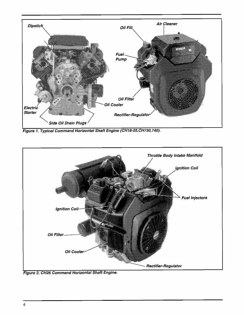
Dipstick \ Air Cleaner Oil Fill, ' Side Oil Drain Plugs / :igure I, Typical Command Horizontal Shaft Engine (CH18-25,CH730,740), Oil anifold Coil lnjecta ' 1 Rectifier-Regula for Figure 2. CH26 Command Horizontal Shaft Engine, 4
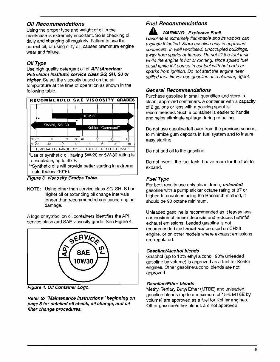
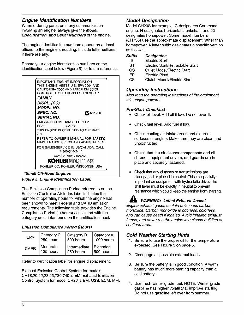
Oil Recommendations Using the proper type and weight of oil in the crankcase is extremely important. So is checking oil daily and changing oil regularly. Failure to use the correct oil, or using dirty oil, causes premature engine wear and failure. Oil Type Use high quality detergent oil of API (American Petroleum Institute) service class SC; SH, SJ or higher. Select the viscosity based on the air temperature at the time of operation as shown in the following table. RECOMMENDED SAE VISCOSITY GRADES v *Use of synthetic oil having 5W-20 or 5W-30 rating is **Syntheticoils will provide better starting in extreme rigure 3. Viscosity Grades Table. acceptable, up to 40°F. cold (below -1 0°F). NOTE: Using other than service class SG, SH, SJ or higher oil or extending oil change intervals longer than recommended can cause engine damage. A logo or symbol on oil containers identifies the API service class and SAE viscosity grade. See Figure 4. Figure 4. Oil Container Logo, Refer to “Maintenance Instructions” beginning on page 8 for detailed oil check, oil change, and oil filter change procedures, Fuel Recommendations Gasoline is extremely flammable and its vapors can explode if ignited. Store gasoline only in approved containers, in well ventilated, unoccupied buildings, away from sparks or flames. Do not fill the fuel tank while the engine is hot or running, since spilled fuel could ignite if it comes in contact with hot parts or sparks from ignition. Do not start the engine near spilled fuel. Never use gasoline as a cleaning agent. WARNING: Explosive Fuel! General Recornmendations Purchase gasoline in small quantities and store in clean, approved containers. A container with a capacity of 2 gallons or less with a pouring spout is recommended. Such a container is easier to handle and helps eliminate spillage during refueling. Do not use gasoline left over from the previous season, to minimize gum deposits in fuel system and to insure easy starting. Do not add oil to the gasoline. Do not overfill the fuel tank. Leave room for the fuel to expand. Fuel Type For best results use only clean, fresh, unleaded gasoline with a pump sticker octane rating of 87 or higher. In countries using the Research method, it should be 90 octane minimum. Unleaded gasoline is recommended as it leaves less combustion chamber deposits and reduces harmful exhaust emissions. Leaded gasoline is not recommended and must not be used on CH26 engine, or on other models where exhaust emissions are regulated. Gasoline/Alcohol blends Gasohol (up to 10% ethyl alcohol, 90% unleaded gasoline by volume) is approved as a fuel for Kohler engines. Other gasoline/alcohol blends are not approved. Gasoline/Ether blends Methyl Tertiary Butyl Ether (MTBE) and unleaded gasoline blends (up to a maximum of 15% MTBE by volume) are approved as a fuel for Kohler engines. Other gasoline/ether blends are not approved. 5
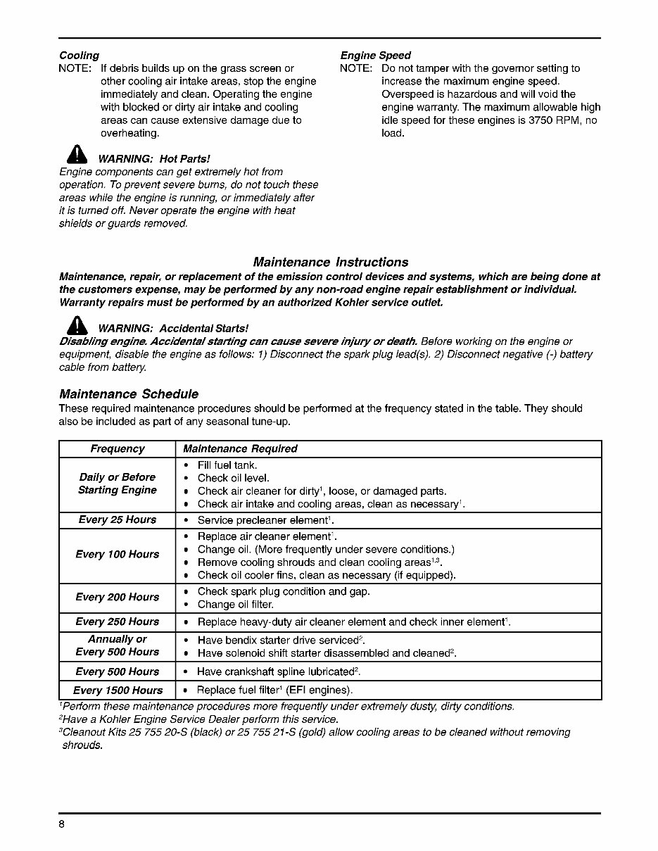
Engine Identification Numbers When ordering parts, or in any communication involving an engine, always give the Model, Specification, and Serial Numbers of the engine. Category C I EPA I 250 hours The engine identification numbers appear on a decal affixed to the engine shrouding. Include letter suffixes, if there are any. Category B Category A 500 hours 1000 hours Record your engine identification numbers on the identification label below (Figure 5) for future reference. Moderate 125 hours -- IMPORTANT ENGINE INFORMATION THIS ENGINE MEETS U.S. EPA 2004 AND Intermediate Extended 250 hours 500 hours CALIFORNIA 2006 AND LATER EMISSION CONTROL REGULATIONS FOR SI SORE* FAMILY DISPL, (CC) MODEL NO, SPEC. NO, eN11236 SERIAL NO, EMISSION COMPLIANCE PERIOD: EPA: CARB: THIS ENGINE IS CERTIFIED TO OPERATE ON: REFER TO OWNER'S MANUAL FOR SAFETY, MAINTENANCE SPECS AND ADJUSTMENTS. FOR SALES/SERVICE IN US/CANADA, CALL: www. kohlerengines.com 1-800-544-2444 u KOHLER CO. KOHLER, WISCONSIN USA *Small Off-Road Engines 7gure 5. Engine ldentifica tion Label, The Emission Compliance Period referred to on the Emission Control or Air Index label indicates the number of operating hours for which the engine has been shown to meet Federal and CARB emission requirements. The following table provides the Engine Compliance Period (in hours) associated with the category descriptor found on the certification label. Emission Compliance Period (Hours) I I Refer to certification label for engine displacement. Exhaust Emission Control System for models CHI 8,20,22,23,25,730,740 is EM. Exhaust Emission Control System for model CH26 is EM, 02S, ECM, MFI. Model Designation Model CH20S for example: C designates Command engine, H designates horizontal crankshaft, and 20 designates horsepower. Some model numbers (CH730) use the approximate displacement rather than horsepower. A letter suffix designates a specific version as follows: Suffix Designates S Electric Start ST Electric StarVRetractable Start QS Quiet ModeVElectric Start EP Electric Plant cs Clutch ModeVElectric Start Operating Instructions Also read the operating instructions of the equipment this engine powers. Pre-Start Checklist Check oil level. Add oil if low. Do not overfill. Check fuel level. Add fuel if low. Check cooling air intake areas and external surfaces of engine. Make sure they are clean and unobstructed. Check that the air cleaner components and all shrouds, equipment covers, and guards are in place and securely fastened. Check that any clutches or transmissions are disengaged or placed in neutral. This is especially important on equipment with hydrostatic drive. The shift lever must be exactly in neutral to prevent resistance which could keep the engine from starting. a WARNING: Lethal Exhaust Gases! Engine exhaust gases contain poisonous carbon monoxide. Carbon monoxide is odorless, colorless, and can cause death if inhaled. Avoid inhaling exhaust fumes, and never run the engine in a closed building or confined area. Cold Weather Starting Hints 1. Be sure to use the proper oil for the temperature expected. See Figure 3 on page 5. 2. Disengage all possible external loads. 3. Be sure the battery is in good condition. A warm battery has much more starting capacity than a cold battery. 4. Use fresh winter grade fuel. NOTE: Winter grade gasoline has higher volatility to improve starting. Do not use gasoline left over from summer. 6
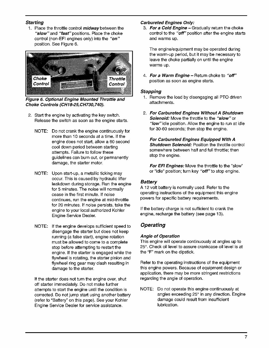
Starting 1. Place the throttle control midway between the “slow” and “fast” positions. Place the choke control (non-EFI engines only) into the “on” position. See Figure 6. Figure 6, Optional Engine Mounted Throttle and Choke Controls (CH18-25, CH730,740), 2. Start the engine by activating the key switch. Release the switch as soon as the engine starts. NOTE: NOTE: NOTE: Do not crank the engine continuously for more than 10 seconds at a time. If the engine does not start, allow a 60 second cool down period between starting attempts. Failure to follow these guidelines can burn out, or permanently damage, the starter motor. Upon start-up, a metallic ticking may occur. This is caused by hydraulic lifter leakdown during storage. Run the engine for 5 minutes. The noise will normally cease in the first minute. If noise continues, run the engine at mid-throttle for 20 minutes. If noise persists, take the engine to your local authorized Kohler Engine Service Dealer. If the engine develops sufficient speed to disengage the starter but does not keep running (a false start), engine rotation must be allowed to come to a complete stop before attempting to restart the engine. If the starter is engaged while the flywheel is rotating, the starter pinion and flywheel ring gear may clash resulting in damage to the starter. If the starter does not turn the engine over, shut off starter immediately. Do not make further attempts to start the engine until the condition is corrected. Do not jump start using another battery (refer to “Battery” on this page). See your Kohler Engine Service Dealer for service assistance. Carbureted Engines Only: 3. 4. For a Cold Engine -Gradually return the choke control to the “off” position after the engine starts and warms up. The engine/equipment may be operated during the warm-up period, but it may be necessary to leave the choke partially on until the engine warms up. For a Warm Engine - Return choke to “off” position as soon as engine starts. Stopping 1. Remove the load by disengaging all PTO driven attachments. 2. For Carbureted Engines WithoutA Shutdown Solenoid: Move the throttle to the “slow” or “low”idle position. Allow the engine to run at idle for 30-60 seconds; then stop the engine. For Carbureted Engines Equipped With A Shutdown Solenoid: Position the throttle control somewhere between half and full throttle; then stop the engine. For EFl Engines: Move the throttle to the “slow” or “idle” position; turn key “off” to stop engine. Battery A 12 volt battery is normally used. Refer to the operating instructions of the equipment this engine powers for specific battery requirements. If the battery charge is not sufficient to crank the engine, recharge the battery (see page 13). Operating Angle of Operation This engine will operate continuously at angles up to 25”. Check oil level to assure crankcase oil level is at the “F’ mark on the dipstick. Refer to the operating instructions of the equipment this engine powers. Because of equipment design or application, there may be more stringent restrictions regarding the angle of operation. NOTE: Do not operate this engine continuously at angles exceeding 25” in any direction. Engine damage could result from insufficient lubrication. 7
Cooling Engine Speed NOTE: If debris builds up on the grass screen or other cooling air intake areas, stop the engine immediately and clean. Operating the engine with blocked or dirty air intake and cooling areas can cause extensive damage due to overheating. load. NOTE: Do not tamper with the governor setting to increase the maximum engine speed. Overspeed is hazardous and will void the engine warranty. The maximum allowable high idle speed for these engines is 3750 RPM, no a WARNING: Hot Parts! Engine components can get extremely hot from operation. To prevent severe burns, do not touch these areas while the engine is running, or immediately after it is turned off. Never operate the engine with heat shields or guards removed. Frequency Daily or Before Starting Engine Maintenance Instructions Maintenance, repai5 or replacement of the emission control devices and systems, which are being done at the customers expense, may be performed by any non-road engine repair establishment or individual, Warranty repairs must be performed by an authorized Kohler service outlet, a WARNING: Accidental Starts! DisabHng engine. Accidenta/staHing can cause severe injury or death. Before working on the engine or equipment, disable the engine as follows: I) Disconnect the spark plug lead@). 2) Disconnect negative (-) battery cable from battery. Maintenance Required Fill fuel tank. Check oil level. Check air cleaner for dirty’, loose, or damaged parts. Check air intake and cooling areas, clean as necessary’. Maintenance Schedule These required maintenance procedures should be performed at the frequency stated in the table. They should also be included as part of any seasonal tune-up. Every 2 5 Hours Every 700 Hours Hours Every250 Hours Service precleaner element’. Replace air cleaner element’. Change oil. (More frequently under severe conditions.) Remove cooling shrouds and clean cooling areas’,3. Check oil cooler fins, clean as necessary (if equipped). Check spark plug condition and gap. Change oil filter. Replace heavy-duty air cleaner element and check inner element’. Every 500 Hours Every 7500 Hours Annually or Have bendix starter drive serviced2. Every 500 Hours Have solenoid shift starter disassembled and cleaned2. Have crankshaft spline lubricated2. Replace fuel filter’ (EFI engines). 8
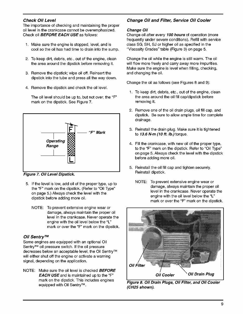
Check Oil Level The importance of checking and maintaining the proper oil level in the crankcase cannot be overemphasized. Check oil BEFORE EACH USE as follows: 1. Make sure the engine is stopped, level, and is cool so the oil has had time to drain into the sump. 2. To keep dirt, debris, etc., out of the engine, clean the area around the dipstick before removing it. 3. Remove the dipstick; wipe oil off. Reinsert the dipstick into the tube and press all the way down. 4. Remove the dipstick and check the oil level. The oil level should be up to, but not over, the “F mark on the dipstick. See Figure 7. I I Operating Range “F” Mark Figure 7. Oil Level Dipstick, 5. If the level is low, add oil of the proper type, up to the “F mark on the dipstick. (Refer to “Oil Type” on page 5.) Always check the level with the dipstick before adding more oil. NOTE: To prevent extensive engine wear or damage, always maintain the proper oil level in the crankcase. Never operate the engine with the oil level below the “L” mark or over the “F’ mark on the dipstick. Oil SentryTM Some engines are equipped with an optional Oil SentryTM oil pressure switch. If the oil pressure decreases below an acceptable level, the Oil SentryTM will either shut off the engine or activate a warning signal, depending on the application. NOTE: Make sure the oil level is checked BEFORE EACH US€ and is maintained up to the “F mark on the dipstick. This includes engines equipped with Oil SentryTM. Change Oil and Filter, Service Oil Cooler Change Oil Change oil after every 100 hours of operation (more frequently under severe conditions). Refill with service class SG, SH, SJ or higher oil as specified in the “Viscosity Grades” table (Figure 3) on page 5. Change the oil while the engine is still warm. The oil will flow more freely and carry away more impurities. Make sure the engine is level when filling, checking, and changing the oil. Change the oil as follows (see Figures 8 and 9): 1. To keep dirt, debris, etc., out of the engine, clean the area around the oil fill cap/dipstick before removing it. 2. Remove one of the oil drain plugs, oil fill cap, and dipstick. Be sure to allow ample time for complete drainage. 3. Reinstall the drain plug. Make sure it is tightened to 13.6 N-m (10 ft. lb.) torque. 4. Fill the crankcase, with new oil of the proper type, to the “F’ mark on the dipstick. Refer to “Oil Type” on page 5. Always check the level with the dipstick before adding more oil. 5. Reinstall the oil fill cap and tighten securely. Reinstall dipstick. NOTE: To prevent extensive engine wear or damage, always maintain the proper oil level in the crankcase. Never operate the engine with the oil level below the “L” mark or over the “F’ mark on the dipstick. oil Cooler ‘ Oil Drain Plug I Figure 8. Oil Drain Plugs, Oil Filter, and Oil Cooler (CH25 shown), 9
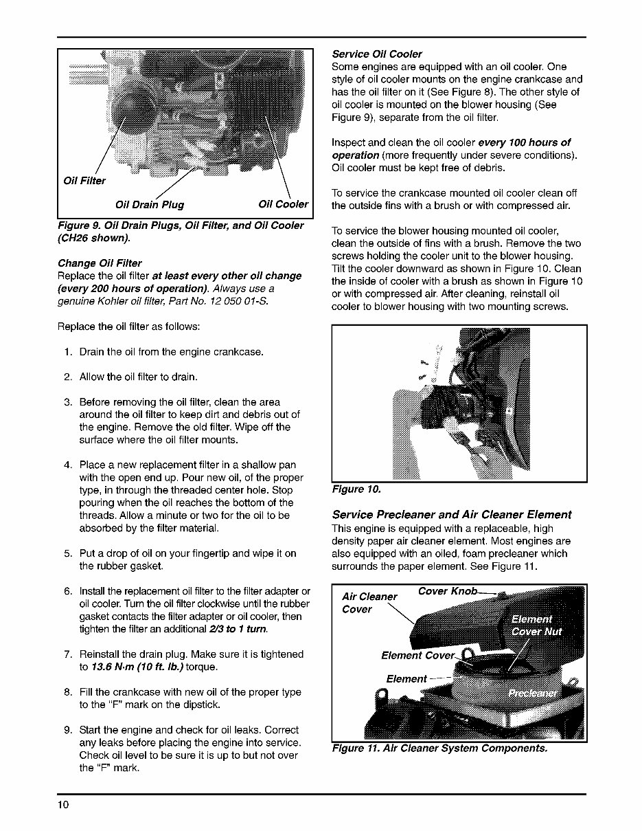
Oil Drain’ Plug oil cooler I I Service Oil Cooler Some engines are equipped with an oil cooler. One style of oil cooler mounts on the engine crankcase and has the oil filter on it (See Figure 8). The other style of oil cooler is mounted on the blower housing (See Figure 9), separate from the oil filter. Inspect and clean the oil cooler every 100 hours of operation (more frequently under severe conditions). Oil cooler must be kept free of debris. To service the crankcase mounted oil cooler clean off the outside fins with a brush or with compressed air. Figure 9. Oil Drain Plugs, Oil Filter, and Oil Cooler (CH26 shown), Change Oil Filter Replace the oil filter at least every other oil change (every 200 hours of operation). Always use a genuine Kohler oil filter, Part No. 12 050 OI-S. Replace the oil filter as follows: 1. Drain the oil from the engine crankcase. 2. Allow the oil filter to drain. 3. Before removing the oil filter, clean the area around the oil filter to keep dirt and debris out of the engine. Remove the old filter. Wipe off the surface where the oil filter mounts. 4. Place a new replacement filter in a shallow pan with the open end up. Pour new oil, of the proper type, in through the threaded center hole. Stop pouring when the oil reaches the bottom of the threads. Allow a minute or two for the oil to be absorbed by the filter material. 5. Put a drop of oil on your fingertip and wipe it on the rubber gasket. 6. Install the replacement oil filter to the filter adapter or oil cooler. Turn the oil filter clockwise until the rubber gasket contacts the filter adapter or oil cooler, then tighten the filter an additional 2/3 to 1 turn. 7. Reinstall the drain plug. Make sure it is tightened to 13.6 N-m (10 ft, lb.) torque. 8. Fill the crankcase with new oil of the proper type to the “F mark on the dipstick. 9. Start the engine and check for oil leaks. Correct any leaks before placing the engine into service. Check oil level to be sure it is up to but not over the “F mark. To service the blower housing mounted oil cooler, clean the outside of fins with a brush. Remove the two screws holding the cooler unit to the blower housing. Tilt the cooler downward as shown in Figure 10. Clean the inside of cooler with a brush as shown in Figure 10 or with compressed air. After cleaning, reinstall oil cooler to blower housing with two mounting screws. Figure 10, Service Precleaner and Air Cleaner Element This engine is equipped with a replaceable, high density paper air cleaner element. Most engines are also equipped with an oiled, foam precleaner which surrounds the paper element. See Figure 11. Figure 11. Air Cleaner System Components, 10
Kohler CH730 Engine Full Service Repair Manual is a comprehensive guide containing all the necessary information for repairing, maintaining, rebuilding, refurbishing, or restoring your Kohler CH730 Engine. It covers diagnostic and repair procedures in great detail, making it useful for both professional technicians and do-it-yourself mechanics.
This manual is a series of practical repair and service manuals used by mechanics worldwide. It includes repair procedures, service schedules, maintenance, wiring diagrams, and diagnostics. The detailed sub-steps expand on repair procedure information, and notes, cautions, and warnings throughout each chapter pinpoint critical information. Numbered instructions and bold figure numbers help you navigate through every repair procedure step by step.
The manual also includes detailed illustrations, drawings, and photos to guide you through every procedure, along with an enlarged inset to help you identify and examine parts in detail. The numbered table of contents makes it easy to find the information you need quickly. Troubleshooting and electrical service procedures are combined with detailed wiring diagrams for ease of use, making it easy to diagnose and repair problems with your machine's electrical system.
The Kohler CH730 Engine Full Service Repair Manual is available in .PDF format, which is compatible with all versions of Windows and Mac. It can be saved to your hard drive and printed, eliminating the need for shipping and waiting for the manual to arrive via mail. Instant access means no shipping costs or waiting for delivery.
The manual covers a wide range of topics including general information, specifications, engine removal, wiring diagrams, lubrication points, oil types, periodic maintenance, tune-up procedures, disassembly, reassembly, fuel and lubrication systems, electrical system, ignition, chassis, suspension, servicing information, service data, tools, tightening torques, gearbox, exhaust system, clutch removal and installation, transmission, cooling system, factory maintenance schedules, electrics, and much more.
Whether you are a professional technician or a DIY enthusiast, the Kohler CH730 Engine Full Service Repair Manual provides all the necessary information to effectively repair and maintain your engine.