FJ400D 4-stroke air-cooled gasoline engine Service Manual chodina@live.co.uk chodina@live.co.uk
chodina@live.co.uk chodina@live.co.uk
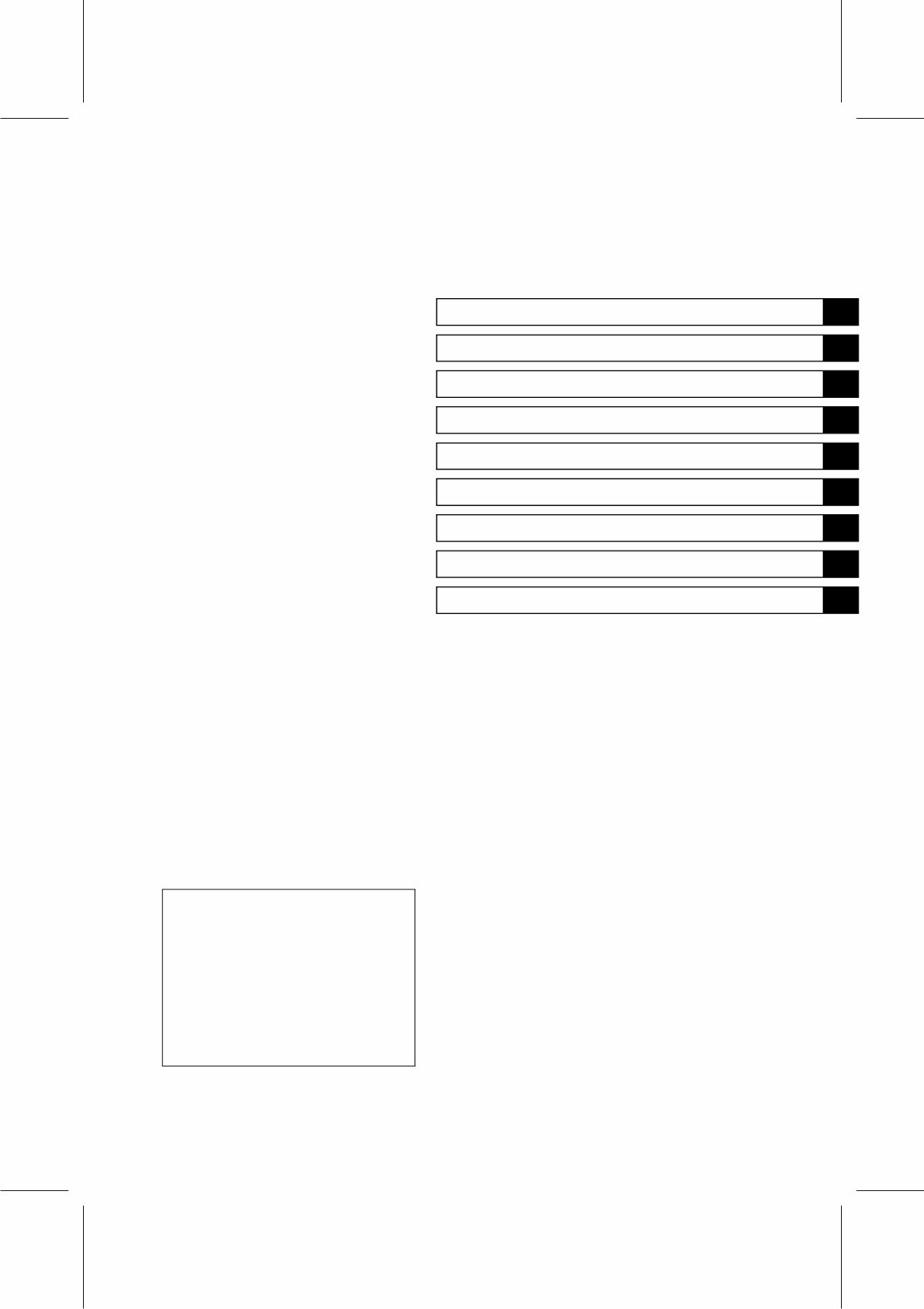
This quick reference guide will assist you in locating a desired topic or pro- cedure. •Bend the pages back to match the black tab of the desired chapter num- ber with the black tab on the edge at each table of contents page. •Refer to the sectional table of contents for the exact pages to locate the spe- cific topic required. Quick Reference Guide General Information 1 Periodic Maintenance 2 Fuel System 3 Cooling System 4 Engine Top End 5 Lubrication System 6 Camshaft/Crankshaft 7 Electrical System 8 Troubleshooting 9 chodina@live.co.uk chodina@live.co.uk
LIST OF ABBREVIATIONS A ampere(s) lb pound(s) ABDC after bottom dead center m meter(s) AC alternating current min minute(s) ATDC after top dead center N newton(s) BBDC before bottom dead center Pa pascal(s) BDC bottom dead center PS horsepower BTDC before top dead center psi pound(s) per square inch °C degree(s) Celsius r revolution DC direct current rpm revolution(s) per minute F farad(s) TDC top dead center °F degree(s) Fahrenheit TIR total indicator reading ft foot, feet V volt(s) g gram(s) W watt(s) h hour(s) Ω ohm(s) L liter(s) Read OWNER’S MANUAL before operating. chodina@live.co.uk chodina@live.co.uk
EMISSION CONTROL INFORMATION To protect the environment in which we all live, Kawasaki has incorporated crankcase emission (1) and exhaust emission (2) control systems (EM) in compliance with applicable regulations of the United States Environmental Protection Agency and California Air Resources Board. 1. Crankcase Emission Control System A sealed-type crankcase emission control system is used to eliminate blow-by gases. The blow-by gases are led to the breather chamber through the crankcase. Then, it is led to the air cleaner. Oil is separated from the gases while passing through the inside of the breather chamber from the crankcase, and then returned back to the bottom of crankcase. 2. Exhaust Emission Control System The exhaust emission control system applied to this engine consists of a carburetor and an ignition system having optimum ignition timing characteristics. The carburetor has been calibrated to provide lean air/fuel mixture characteristics and optimum fuel economy with a suitable air cleaner and exhaust system. TAMPERING WITH EMISSION CONTROL SYSTEM PROHIBITED Federal law and California State law prohibits the following acts or the causing thereof: (1) the removal or rendering inoperative by any person other than for purposes of maintenance, repair, or replacement, of any device or element of design incorporated into any new engine for the purpose of emission control prior to its sale or delivery to the ultimate purchaser or while it is in use, or (2) the use of the engine after such device or element of design has been removed or rendered inoperative by any person. Among those acts presumed to constitute tampering are the acts listed below: Do not tamper with the original emission related part. • Carburetor and internal parts • Spark plug • Magneto or electronic ignition system • Fuel filter element • Air cleaner element • Crankcase • Cylinder head • Breather chamber and internal parts • Inlet pipe and tube chodina@live.co.uk chodina@live.co.uk
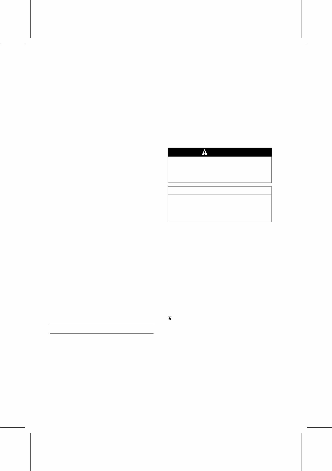
Foreword This manual is designed primarily for use by trained mechanics in a properly equipped shop. However, it contains enough detail and basic in- formation to make it useful to the owner who de- sires to perform his own basic maintenance and repair work. A basic knowledge of mechanics, the proper use of tools, and workshop proce- dures must be understood in order to carry out maintenance and repair satisfactorily. When- ever the owner has insufficient experience or doubts as to his ability to do the work, all ad- justments, maintenance, and repair should be carried out only by qualified mechanics. In order to perform the work efficiently and to avoid costly mistakes, read the text, thor- oughly familiarize yourself with the procedures before starting work, and then do the work care- fully in a clean area. Whenever special tools or equipment are specified, do not use makeshift tools or equipment. Precision measurements can only be made if the proper instruments are used, and the use of substitute tools may ad- versely affect safe operation. To get the longest life out of your engine: • Follow the Periodic Maintenance Chart in the Service Manual. • Be alert for problems and non-scheduled maintenance. • Use proper tools and genuine Kawasaki en- gine parts. Genuine parts provided as spare parts are listed in the Parts Catalog. • Follow the procedures in this manual care- fully. Don’t take shortcuts. • Remember to keep complete records of main- tenance and repair with dates and any new parts installed. How to Use This Manual In this manual, the product is divided into its major systems and these systems make up the manual’s chapters. The Quick Reference Guide shows you all of the product’s system and assists in locating their chapters. Each chapter in turn has its own comprehensive Ta- ble of Contents. For example, if you want ignition coil informa- tion, use the Quick Reference Guide to locate the Electrical System chapter. Then, use the Table of Contents on the first page of the chap- ter to find the Ignition coil section. Whenever you see these WARNING and CAUTION symbols, heed their instructions! Always follow safe operating and maintenance practices. WARNING This warning symbol identifies special instructions or procedures which, if not correctly followed, could result in per- sonal injury, or loss of life. CAUTION This caution symbol identifies special instructions or procedures which, if not strictly observed, could result in dam- age to or destruction of equipment. This manual contains four more symbols (in addition to WARNING and CAUTION) which will help you distinguish different types of informa- tion. NOTE ○ This note symbol indicates points of par- ticular interest for more efficient and con- venient operation. • Indicates a procedural step or work to be done. ○ Indicates a procedural sub-step or how to do the work of the procedural step it follows. It also precedes the text of a WARNING, CAU- TION, or NOTE. Indicates a conditional step or what action to take based on the results of the test or inspec- tion in the procedural step or sub-step it fol- lows. In most chapters an exploded view illustration of the system components follows the Table of Contents. In these illustrations you will find the instructions indicating which parts require spec- ified tightening torque, oil, grease or a locking agent during assembly. chodina@live.co.uk chodina@live.co.uk
GENERAL INFORMATION 1-1 1 General Information Table of Contents Before Servicing ..................................................................................................................... 1-2 Model Identification................................................................................................................. 1-4 General Specifications............................................................................................................ 1-5 chodina@live.co.uk chodina@live.co.uk
1-2 GENERAL INFORMATION Before Servicing Before starting to service the engine, carefully read the applicable section to eliminate unnecessary work. Photographs, diagrams, notes, cautions, warnings, and detailed descriptions have been in- cluded wherever necessary. Nevertheless, even a detailed account has limitations, a certain amount of basic knowledge is required for successful work. Especially note the following (1) Dirt Before removal and disassembly, clean the engine. Any dirt entering the engine, carburetor, or other parts, will work as an abrasive and shorten the life of engine. For the same reason, before installing a new part, clean off any dust or metal filings. (2) Tightening Sequence Generally, when installing a part with several bolts, nuts, or screws, start them all in their holes and tighten them to a snug fit. Then tighten them evenly, in a staggered sequence. This is to avoid distortion of the part and/or causing gas or oil leakage. Conversely when loosening the bolts, nuts, or screws, first loosen all of them by about a quarter of a turn and then remove them. Where there is a tightening sequence indication in this Service Manual, the bolts, nuts, or screws must be tightened in the order and method indicated. (3) Torque When torque values are given in this Service Manual, use them. Either too little or too much torque may lead to serious damage. Use a good quality, reliable torque wrench. (4) Force Common sense should dictate how much force is necessary in assembly and disassembly. If a part seems especially difficult to remove or install, stop and examine what may be causing the problem. Whenever tapping is necessary, tap lightly using a wooden or plastic-faced mallet. Use an impact driver for screws (particularly for the removal of screws held by a locking agent) in order to avoid damaging the heads. (5) Edges Watch for sharp edges, especially during major engine disassembly and assembly. Protect your hands with gloves or a piece of thick cloth when lifting the engine or turning it over. (6) High-Flash Point Solvent A high-flash point solvent is recommended to reduce fire danger. A commercial solvent com- monly available in North America is Standard solvent (generic name). Always follow manufacturer and container directions regarding the use of any solvent. (7) Gasket, O-ring Do not reuse a gasket or O-ring once it has been in service. The mating surfaces around the gasket should be free of foreign matter and perfectly smooth to avoid oil or compression leaks. (8) Liquid Gasket, Non-Permanent Locking Agent Follow manufacturer’s directions for cleaning and preparing surfaces where these compounds will be used. Apply sparingly. Excessive amounts may block engine oil passages and cause serious damage. An example of a non-permanent locking agent commonly available in North America is Loctite Lock’n Seal (Blue). (9) Press A part installed using a press or driver, such as a journal, should first be coated with oil on its outer or inner circumference so that it will go into place smoothly. (10)Ball Bearing, Needle Bearing Do not remove a ball bearing or a needle bearing unless it is absolutely necessary. Replace any ball or needle bearings that were removed with new ones. Install bearings with the manufacturer and size marks facing out, applying pressure evenly with a suitable driver to the end of the race that contacts the press fit portion, and press it evenly over the base component. (11)Oil Seal and Grease Seal Replace any oil or grease seals that were removed with new ones, as removal generally dam- ages seals. When pressing in a seal which has manufacturer’s marks, press it in with the marks facing out. Seals should be pressed into place using a suitable driver, which contacts evenly with the side of seal, until the face of the seal is even with the end of the hole. chodina@live.co.uk chodina@live.co.uk
This complete factory Kawasaki FJ400D 4-stroke air-cooled gasoline engines service repair manual is an invaluable technical resource for maintaining and servicing your equipment. It includes detailed diagrams, manufacturer specifications, and instructions for various procedures.
Whether you are a professional mechanic or a DIY enthusiast, this manual offers simple navigation with convenient chapter bookmarks and the ability to search by keyword. The fully bookmarked chapters allow for easy identification of service repair procedures, while detailed illustrations, exploded diagrams, drawings, and photos guide you through each step.
The manual covers a wide range of sections including general information, periodic maintenance, fuel system, cooling system, engine top end, lubrication system, cam shaft/crankshaft, electrical system, and troubleshooting. It is fully indexed, bookmarked, and searchable, making it easy to find the information you need quickly.
With an excellent layout and sequencing of detailed information, this manual is great for tune-ups, regular maintenance, or repairs. It provides technical details and step-by-step instructions for various procedures, making it an essential tool for anyone working with Kawasaki FJ400D engines.
Whether you prefer to print out the entire manual or just the sections you'll be working on, this manual is compatible with both Windows and Mac systems. It is available in English and contains 129 pages of searchable, bookmarked, and indexed content.
For immediate access to this manual, simply click the green and white button at the top right-hand side of this page. If you encounter any issues with viewing the document, ensure that you have the latest version of Adobe Acrobat Reader installed.
For any additional information or inquiries about other manuals, feel free to email us. We have thousands of manuals available to meet your specific needs.