LIST OF ABBREVIATIONS A ampere(s) lb pound(s) ABDC after bottom dead center m meter(s) AC alternating current min minute(s) ATDC after top dead center N newton(s) BBDC before bottom dead center Pa pascal(s) BDC bottom dead center PS horsepower BTDC before top dead center psi pound(s) per square inch C degree(s) Celsius r revolution DC direct current rpm revolution(s) per minute F farad(s) TDC top dead center F degree(s) Fahrenheit TIR total indicator reading ft foot, feet V volt(s) g gram(s) W watt(s) h hour(s) ohm(s) L liter(s) Read OWNER’S MANUAL before operating.
EMISSION CONTROL INFORMATION To protect the environment in which we live, Kawasaki has incorporated crankcase emission (1) and exhaust emission (2) control systems in compliance with applicable regulations of the United States Environmental Protection Agency and the California Air Resources Board. 1. Crankcase Emission Control System A sealed-type crankcase emission control system is used to eliminate blow-by gasses. The blow-by gasses are led to a breather chamber through the crankcase and from there to the air cleaner. Oil is separated from the gasses while passing through the inside of the breather chamber from the crankcase, and then returned to the bottom of the crankcase. 2. Exhaust Emission Control System The exhaust emission control system applied to this engine consists of a carburetor and an ignition system having optimum ignition timing characteristics. The carburetor has been calibrated to provide lean air/fuel mixture characteristics and optimum fuel economy with a suitable air cleaner and exhaust system. TAMPERING WITH EMISSION CONTROL SYSTEM PROHIBITED Federal law and California State law prohibits the following acts or the causing thereof: (1) the removal or rendering inoperative by any person other than for purposes of maintenance, repair, or replacement, of any device or element of design incorporated into any new engine for the purpose of emission control prior to its sale or delivery to the ultimate purchaser or while it is in use, or (2) the use of the engine after such device or element of design has been removed or rendered inoperative by any person. Among those acts presumed to constitute tampering are the acts listed below: Do not tamper with the original emission related part. • Carburetor and internal parts • Spark plugs • Magneto or electronic ignition system • Fuel filter element • Air cleaner elements • Crankcase • Cylinder heads • Breather chamber and internal parts • Intake pipe and tube
Foreword This manual is designed primarily for use by trained mechanics in a properly equipped shop. However, it contains enough detail and basic information to make it useful to the owner who desires to perform his own basic maintenance and repair work. A basic knowledge of mechanics, the proper use of tools, and workshop procedures must be understood in order to carry out maintenance and repair satisfactorily. Whenever the owner has insufficient experience or doubts as to his ability to do the work, all adjustments, maintenance, and repair should be carried out only by qualified mechanics. In order to perform the work efficiently and to avoid costly mistakes, read the text, thoroughly familiarize yourself with the procedures before starting work, and then do the work carefully in a clean area. Whenever special tools or equipment are specified, do not use makeshift tools or equipment. Precision measurements can only be made if the proper instruments are used, and the use of substitute tools may adversely affect safe operation. To get the longest life out of your engine: • Follow the Periodic Maintenance Chart in the Service Manual. • Be alert for problems and non-scheduled maintenance. • Use proper tools and genuine Kawasaki engine parts. Genuine parts provided as spare parts are listed in the Parts Catalog. • Follow the procedures in this manual carefully. Don’t take shortcuts. • Remember to keep complete records of maintenance and repair with dates and any new parts installed. How to Use This Manual In preparing this manual, we divided the product into its major systems. These systems became the manual’s chapters. All information for a particular system from adjustment through disassembly and inspection is located in a single chapter. The Quick Reference Guide shows you all of the product’s system and assists in locating their chapters. Each chapter in turn has its own comprehensive Table of Contents. The Periodic Maintenance Chart is located in the General Information chapter. The chart gives a time schedule for required maintenance operations. If you want spark plug information, for example, go to the Periodic Maintenance Chart first. The chart tells you how frequently to clean and gap the plug. Next, use the Quick Reference Guide to locate the Electrical System chapter. Then, use the Table of Contents on the first page of the chapter to find the Spark Plug section. Whenever you see these WARNING and CAUTION symbols, heed their instructions! Always follow safe operating and maintenance practices. This warning symbol identifies special instruc- tions or procedures which, if not correctly fol- lowed, could result in personal injury, or loss of life. CAUTION This caution symbol identifies special instruc- tions or procedures which, if not strictly ob- served, could result in damage to or destruction of equipment. This manual contains four more symbols (in addition to WARNING and CAUTION) which will help you distinguish different types of information. NOTE This note symbol indicates points of particular in- terest for more efficient and convenient operation. • Indicates a procedural step or work to be done. Indicates a procedural sub-step or how to do the work of the procedural step it follows. It also precedes the text of a WARNING, CAUTION, or NOTE. Indicates a conditional step or what action to take based on the results of the test or inspection in the procedural step or sub-step it follows. In most chapters an exploded view illustration of the system components follows the Table of Contents. In these illustrations you will find the instructions indicating which parts require specified tightening torque, oil, grease or a locking agent during assembly.
GENERAL INFORMATION 1-1 General Information Table of Contents 1 Before Servicing ................................................................................................................................................................. 1-2 General Specifications ....................................................................................................................................................... 1-4 Periodic Maintenance Chart ............................................................................................................................................... 1-6 Special Tools ...................................................................................................................................................................... 1-7 Exploded View....................................................................................................................................................................1-8
1-2 GENERAL INFORMATION Before Servicing Before starting to service the engine, carefully read the applicable section to eliminate unnecessary work. Photographs, diagrams, notes, cautions, warnings, and detailed descriptions have been included wherever necessary. Nevertheless, even a detailed account has limitations, a certain amount of basic knowledge is required for successful work. Especially note the following: (1) Dirt Before removal and disassembly, clean the engine. Any dirt entering the engine, carburetor, or other parts, will work as an abrasive and shorten the life of engine. For the same reason, before installing a new part, clean off any dust or metal filings. (2) Battery Ground Remove the ground (—) lead from the battery before performing any disassembly operations on the equipment. This prevents: (a) the possibility of accidentally turning the engine over while partially disassembled. (b) sparks at electrical connections which will occur when they are disconnected. (c) damage to electrical parts. (3) Tightening Sequence Generally, when installing a part with several bolts, nuts, or screws, start them all in their holes and tighten them to a snug fit. Then tighten them evenly, in a staggered sequence. This is to avoid distortion of the part and/or causing gas or oil leakage. Conversely, when loosening the bolts, nuts, or screws, first loosen all of them by about a quarter of a turn and then remove them. Where there is a tightening sequence indication in this Service Manual, the bolts, nuts, or screws must be tightened in the order and method indicated. (4) Torque When torque values are given in this Service Manual, use them. Either too little or too much torque may lead to serious damage. Use a good quality, reliable torque wrench. (5) Force Common sense should dictate how much force is necessary in assembly and disassembly. If a part seems especially difficult to remove or install, stop and examine what may be causing the problem. Whenever tapping is necessary, tap lightly using a wooden or plastic-faced mallet. Use an impact driver for screws (particularly for the removal of screws held by a locking agent) in order to avoid damaging the heads. (6) Edges Watch for sharp edges, especially during major engine disassembly and assembly. Protect your hands with gloves or a piece of thick cloth when lifting the engine or turning it over. (7) High-Flash Point Solvent A high-flash point solvent is recommended to reduce fire danger. A commercial solvent commonly available in North America is Standard solvent (generic name). Always follow manufacturer and container directions regarding the use of any solvent. (8) Gasket, O-Ring Do not reuse a gasket or O-ring once it has been in service. The mating surfaces around the gasket should be free of foreign matter and perfectly smooth to avoid oil or compression leaks. (9) Liquid Gasket, Non-Permanent Locking Agent Follow manufacturer’s directions for cleaning and preparing surfaces where these compounds will be used. Apply sparingly. Excessive amounts may block engine oil passages and cause serious damage. An example of a non- permanent locking agent commonly available in North America is Loctite Lock’n Seal (Blue). (10) Press A part installed using a press or driver, such as a journal, should first be coated with oil on its outer or inner circumference so that it will go into place smoothly. (11) Ball Bearing When installing a ball bearing, the bearing race which is affected by friction should be pushed by a suitable driver. This prevents severe stress on the balls and races, and prevents races and balls from being dented. Press a ball bearing until it stops at the stop in the hole or on the shaft. (12) Oil Seal and Grease Seal Replace any oil or grease seals that were removed with new ones, as removal generally damages seals. When pressing in a seal which has manufacturer’s marks, press it in with the marks facing out. Seals should be pressed into place using a suitable driver, which contacts evenly with the side of seal, until the face of the seal is even with the end of the hole. (13) Seal Guide A seal guide is required for certain oil or grease seals during installation to avoid damage to the seal lips. Before a shaft passes through a seal, apply a little oil, preferably high temperature grease on the lips to reduce rubber to metal friction. (14) Circlip, Retaining Ring Replace any circlips and retaining rings that were removed with new ones, as removal weakens and deforms them. When installing circlips and retaining rings, take care to compress or expand them only enough to install them and no more.
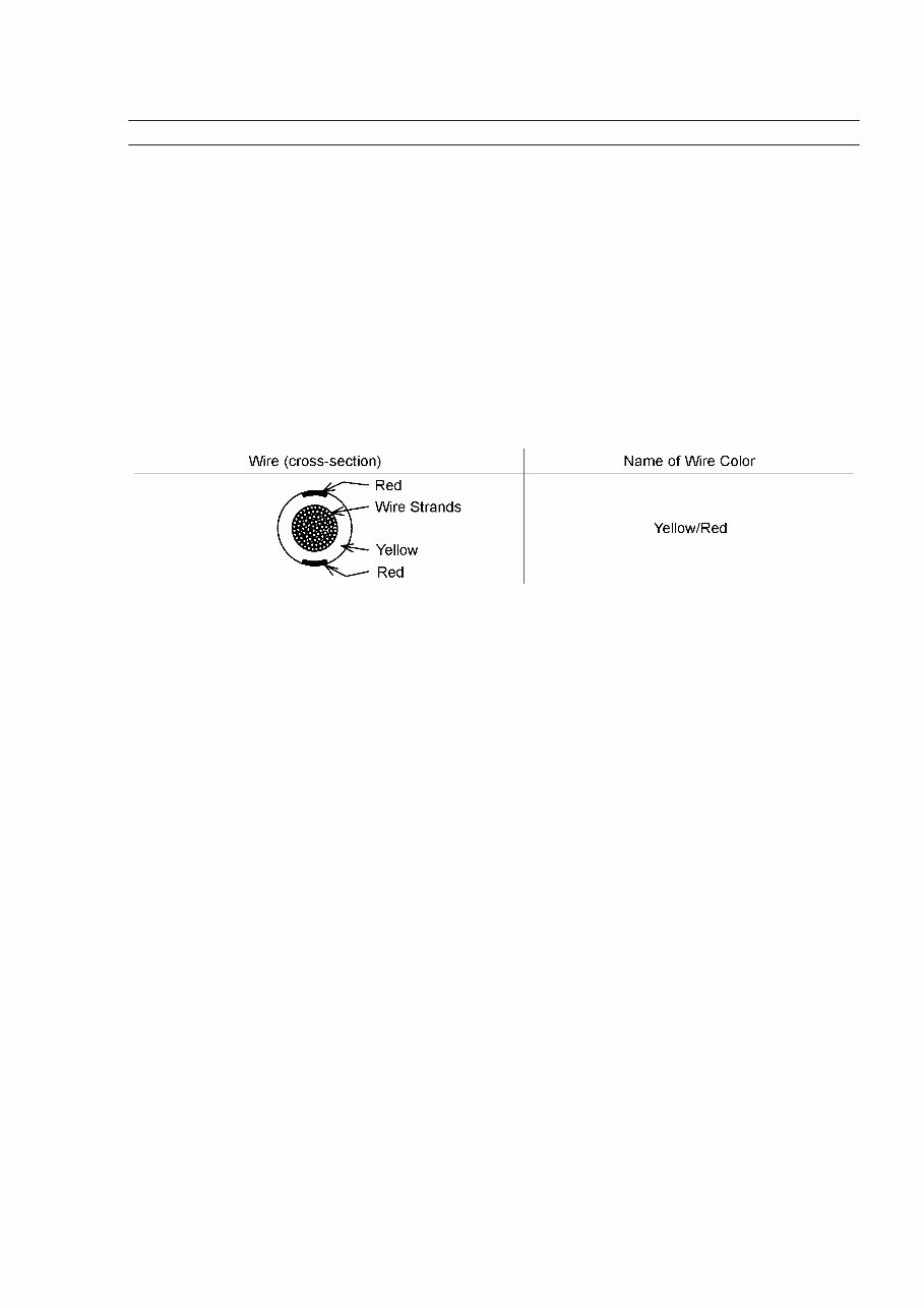
GENERAL INFORMATION 1-3 Before Servicing (15) Cotter Pin Replace any cotter pins that were removed with new ones, as removal deforms and breaks them. (16) Lubrication Engine wear is generally at its maximum while the engine is warming up and before all the rubbing surfaces have an adequate lubricative film. During assembly, oil or grease (whichever is more suitable) should be applied to any rubbing surface which has lost its lubricative film. Old grease and dirty oil should be cleaned off. Deteriorated grease has lost its lubricative quality and may contain abrasive foreign particles. Don’t use just any oil or grease. Some oils and greases in particular should be used only in certain applications and may be harmful if used in an application for which they are not intended. This manual makes reference to molybdenum disulfide grease (MoS2) in the assembly of certain engine parts. Always check manufacturer recommendations before using such special lubricants. (17) Electrical Wires All the electrical wires are either single-color or two-color and, with only a few exceptions, must be connected to wires of the same color. On any of the two-color wires there is a greater amount of one color and a lesser amount of a second color, so a two-color wire is identified by first the primary color and then the secondary color. For example, a yellow wire with thin red stripes is referred to as a "yellow/red" wire; it would be a "red/yellow" wire if the colors were reversed to make red the main color. (18) Replacement Parts When there is a replacement instruction, replace these parts with new ones every time they are removed. There replacement parts will be damaged or lose their original function once removed. (19) Inspection When parts have been disassembled, visually inspect these parts for the following conditions or other damage. If there is any doubt as to the condition of them, replace them with new ones. Abrasion Crack Hardening Warp Bent Dent Scratch Wear Color change Deterioration Seizure (20) Specifications Specification terms are defined as follows: "Standards" show dimensions or performances which brand-new parts or systems have. "Service Limits" indicate the usable limits. If the measurement shows excessive wear or deteriorated performance, replace the damaged parts.
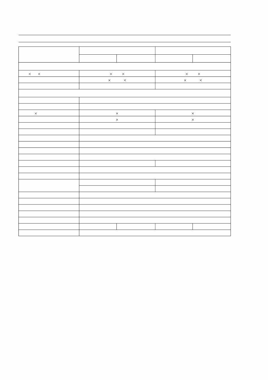
1-4 GENERAL INFORMATION General Specifications Item FE120 FE170 Type D Type G Type D Type G Dimensions: L W H mm 291 349 344 300 354 370 in 11.46 13.43 19.54 11.81 13.94 14.57 Dry Weight kg 14.5 16.8 Engine: Type of engine Air cooled, 4-stroke, OHV, Single cylinder, Gasoline engine Number of Cylinder 1 Bore Stroke mm 60 44 66 50 in 2.36 1.73 2.60 1.97 Displacement mL 124 171 cu.in 7.6 10.4 Direction of rotarion Counterclockwise facing PTO Shaft Fast Idle Speed rpm 4000 Slow Idle Speed rpm 1600 Fuel information Unleaded Gasoline Fuel tank capacity L 2.5 3.4 Lubrication system Splash Engine Oil SAE 10W30 (SF, SG, SH, or SJ) Oil Pan Capacity Max. 0.6 L 0.6 L Min. 0.35 L 0.35 L Carburetor Float, Butterfly Type Ignition system Transistor Flywheel Magneto Spark Plug NGK BPR 5ES Starting system Recoil starter with ACR or electric starter Governor Mechanical flyweight Type of Reduction --- 1/2 gear reduction --- 1/2 gear reduction Air Cleaner Dual Element Specifications are subject to change without notice, and may not apply to every country.
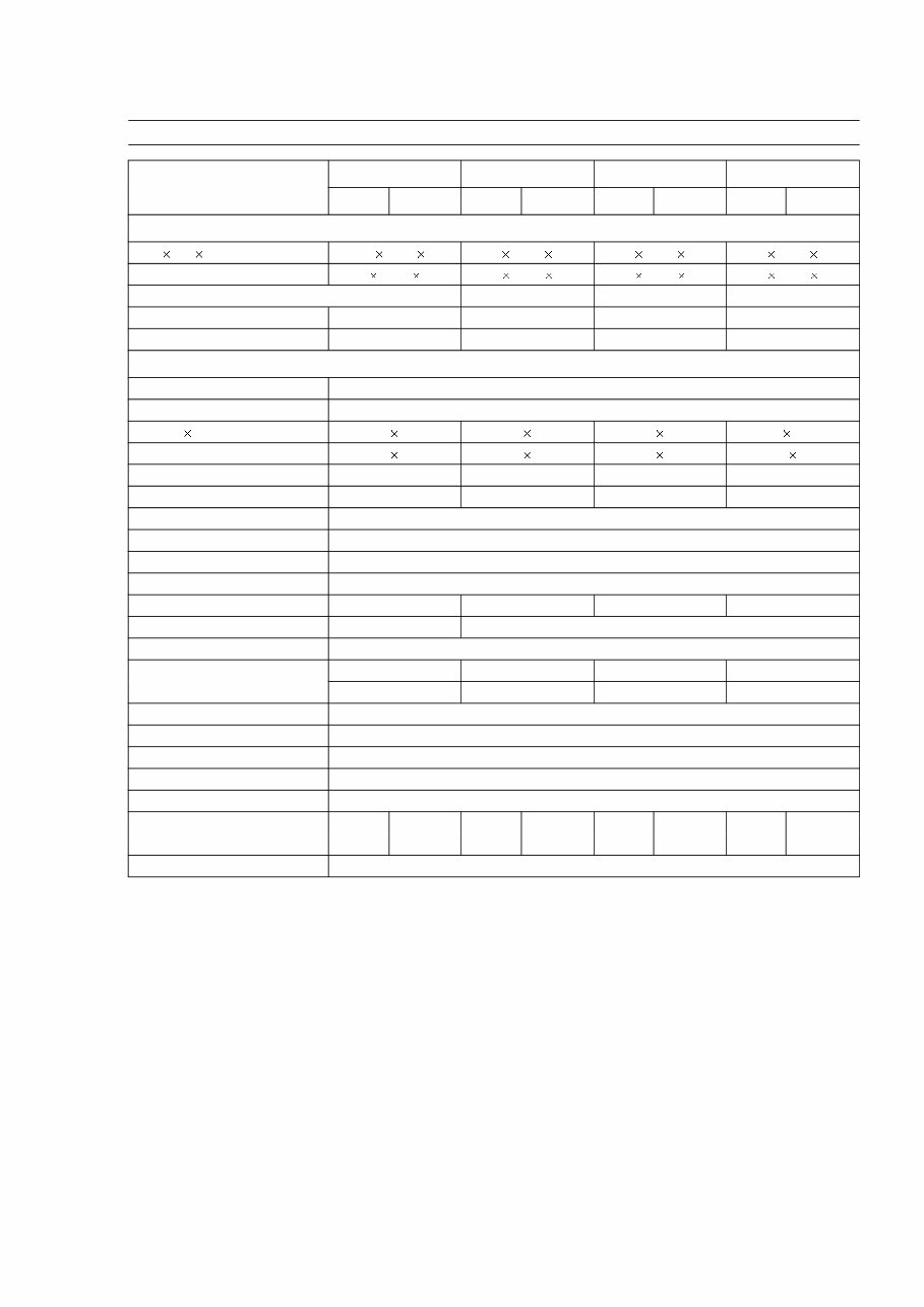
GENERAL INFORMATION 1-5 General Specifications Item FE250 FE290 FE350 FE400 Type D Type G Type D Type G Type D Type G Type D Type G Dimensions: L W H mm 344.5 395 432 363 408 441 378 422 454 378 422 459 in 13.56 15.55 17.01 14.29 16.06 17.36 14.88 16.61 17.87 14.88 16.61 18.07 Dry Weight With recoil starter kg 26.8 30.4 34.4 34.5 With erectic starter kg 30.0 33.6 38.2 38.5 Engine: Type of engine Air cooled, 4-stroke, OHV, Single cylinder, Gasoline engine Number of Cylinder 1 Bore Stroke mm 76 55 78 60 83 65 87 67.5 in 2.99 2.17 3.07 2.36 3.27 2.56 3.43 2.66 Displacement mL 249 286 351 401 cu.in 15.2 17.5 21.4 24.5 Direction of rotation Counterclockwise facing PTO Shaft Fast Idle Speed rpm 4000 Slow Idle Speed rpm 1300 Fuel information Unleaded Gasoline Fuel tank capacity L 5.3 6.0 6.4 6.4 Lubrication system Splash Pressurized lubrication with oil filter Engine Oil SAE 10W30 (SF, SG, SH, or SJ) Oil Pan Capacity Max. 1.1 L 1.1 L 1.3 L 1.3 L Min. 0.8 L 0.8 L 1.0 L 1.0 L Carburetor Float, Butterfly Type Ignition system Transistor flywheel magneto Spark Plug NGK BPR 5ES Starting system Recoil starter with ACR or electric starter Governor Mechanical flyweight Type of Reduction – 1/2 gear – 1/2 gear – 1/2 gear – 1/2 gear reduction reduction reduction reduction Air Cleaner Dual Element Specifications are subject to change without notice, and may not apply to every country.
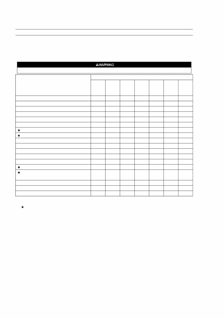
1-6 GENERAL INFORMATION Periodic Maintenance Chart To ensure satisfactory operation over an extended period of time, any engine requires normal maintenance regular intervals. The Periodic Maintenance Chart below shows periodic inspection and maintenance items and suitable intervals. The bullet mark (•) designates that the corresponding item should be performed at that interval. Some adjustments require the use of special tools or other equipment. An electronic tachometer will facilitate setting idle and running speeds. Always remove the spark plug cap from spark plug when servicing the engine to prevent accidental starting. INTERVAL MAINTENANCE Daily First Every Every Every Every Every 8 25 50 100 200 300 hr. hr. hr. hr. hr. hr. Check and add engine oil, • Check for loose or lost nuts and screws • Check for fuel and oil leakage • Check battery electrolyte level • Check or clean air intake screen • Tighten nuts and screws • Clean air cleaner foam element • Clean air cleaner paper element • Clean fuel filter element • Change engine oil (without oil filer) • • Change engine oil (with oil filer) • • Clean and regap spark plug • Change oil filter • Replace air cleaner paper element • Clean dust and dirt from cylinder • and cylinder head fines K Clean combustion chamber • K Check and adjust valve clearance • K Clean and lap valve seating surface • NOTE: The service intervals indicated are to be used as a guide. Service should be performed more frequently as necessary by operating condition. : Service more frequently under dusty conditions. K: Have an authorized Kawasaki engine dealer perform those services.
Save money on service, repair, and maintenance costs with this comprehensive Service Repair Workshop Manual. It contains all the information needed to repair, maintain, rebuild, refurbish, or restore your vehicle. The manual is easy to use and covers all repairs from A to Z.
Professional technicians and mechanics use this manual for diagnostic and repair procedures, and now you can access the same detailed, printable diagrams they rely on. Simply print out the required information and start the repair, or take your laptop/tablet to the vehicle for easy reference.
Whether you're a professional mechanic or a DIY enthusiast, this manual is designed to be user-friendly and doesn't require special technical know-how. In the rare event that you need technical assistance, support is readily available via email.
Upon payment receipt, you will receive an instant delivery email with a link to download the manual. There are no restrictions on usage, so you can refer to the manual as many times as needed.
While we take pride in delivering high-quality products, refunds are not available due to the nature of this item. However, if you encounter any issues, a replacement link will be promptly provided upon email request.
This manual is compatible with both PC and MAC computers and is available in Adobe PDF format. It operates on various Windows platforms, ensuring accessibility for a wide range of users.
Don't delay - get the job done today and save on repair and maintenance costs. This manual is your comprehensive guide to fixing your vehicle the first time.
Service manual
Repair manual
FSM manual
Service repair workshop manual
Factory manual
Shop manual
Maintenance manual
DIY manual
Automotive repairs
Diagnostics manual
ATV repair
Jetski repairs
Motorcycle repairs
Car repair
Outboard engine repair
Snowmobile repairs
And more...
Recently Viewed
5,521,897Happy Clients
2,594,462eManuals
1,120,453Trusted Sellers
15Years in Business
Price:
Actual Price:
2000-2008 Club Car Kawasaki FE120 FE170 FE250 FE290 FE350 FE400 4 Stroke Engine Service & Repair Manual