


COMPONENT
TECHNICAL
MANUAL
Litho in U.S.A
John Deere
Lawn & Grounds Care Division
John Deere K Series
Liquid-cooled Engines
CTM39 (Oct93)
Replaces CTM39 (28JAN91)
INTRODUCTION
4/7/95 1 - 1
This component technical manual is written for an
experienced technician. It covers recommended repair
procedures, starting with the engine removed from the
machine and on a workbench or engine stand. Some
components may be serviced in the machine.
Determine the repair procedure before removing the
engine. Use this manual in conjunction with the
machine technical manual. It is a part of a total product
support program. Use the Fundamental Of Service
(FOS) manual as reference for fundamentals of service
and basic theory of operation.
The manual is organized so that all the information on
a particular system is kept together. The order of
grouping is as follows:
• Table of Contents
• Safety
• Specifications
• Theory of Operation
• Repair
Note: Depending on the particular section or system
being covered, not all of the above groups may
be used.
Each section will be identified with a symbol rather than
a number. The pages within a section will be
consecutively numbered.
All information, illustrations and specifications in this
manual are based on the latest information available at
the time of publication. The right is reserved to make
changes at any time without notice.
We appreciate your input on this manual. To help, there
are postage paid post cards included at the back. If you
find any errors or want to comment on the layout of the
manual please fill out one of the cards and mail it back
to us.
COPYRIGHT
©
1993
JOHN DEERE HORICON WORKS
Horicon, Wisconsin
All rights reservedl
Information
Specifications and
Intake, Muffler & Breather
Cylinder Head & Valves
Camshaft, Crankshaft &
Lubrication System
Cooling System
Electrical System
Component Analysis
Fuel System & Governor
Safety
Miscellaneous
Cylinder Block, Pistons & Rods
Troubleshooting
Flywheel
SAFETY
1 - 2 4/7/95
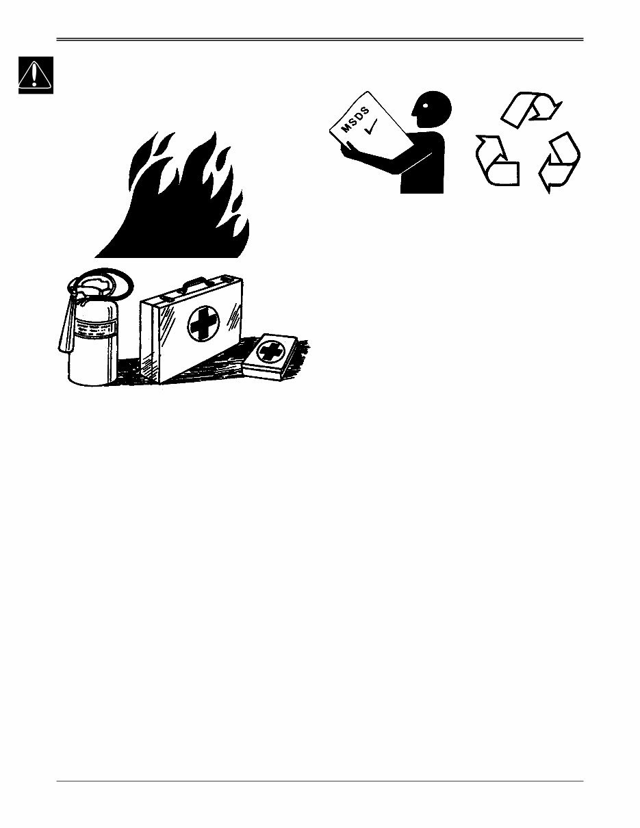
HANDLE FLUIDS SAFELY-AVOID
FIRES
• BE PREPARED FOR EMERGENCIES
When you work around fuel, do not smoke or work near
heaters or other fire hazards.
Store flammable fluids away from fire hazards. Do not
incinerate or puncture pressurized containers.
Make sure machine is clean of trash, grease, and
debris.
Do not store oily rags; they can ignite and burn
spontaneously.
Be prepared if a fire starts.
Keep a first aid kit and fire extinguisher handy.
Keep emergency numbers for doctors, ambulance
service, hospital, and fire department near your
telephone.
TS227
TS291
HANDLE CHEMICAL PRODUCTS
SAFELY
Direct exposure to hazardous chemicals can cause
serious injury. Potentially hazardous chemicals used
with John Deere equipment include such items as
lubricants, coolants, paints, and adhesives.
A Material Safety Data Sheet (MSDS) provides specific
details on chemical products: physical and health
hazards, safety procedures, and emergency response
techniques. Check the MSDS before you start any job
using a hazardous chemical. That way you will know
exactly what the risks are and how to do the job safely.
Then follow procedures and recommended equipment.
• DISPOSE OF WASTE PROPERLY
Improperly disposing of waste can threaten the
environment and ecology. Potentially harmful waste
used with John Deere equipment include such items as
oil, fuel, coolant, brake fluid, filters, and batteries. Use
leakproof containers when draining fluids. Do not use
food or beverage containers that may mislead
someone into drinking from them. Do not pour waste
onto the ground, down a drain, or into any water
source. Inquire on the proper way to recycle or dispose
of waste from your local environmental or recycling
center, or from your John Deere dealer.
TS1133
TS1132
SAFETY
4/7/95 1 - 3
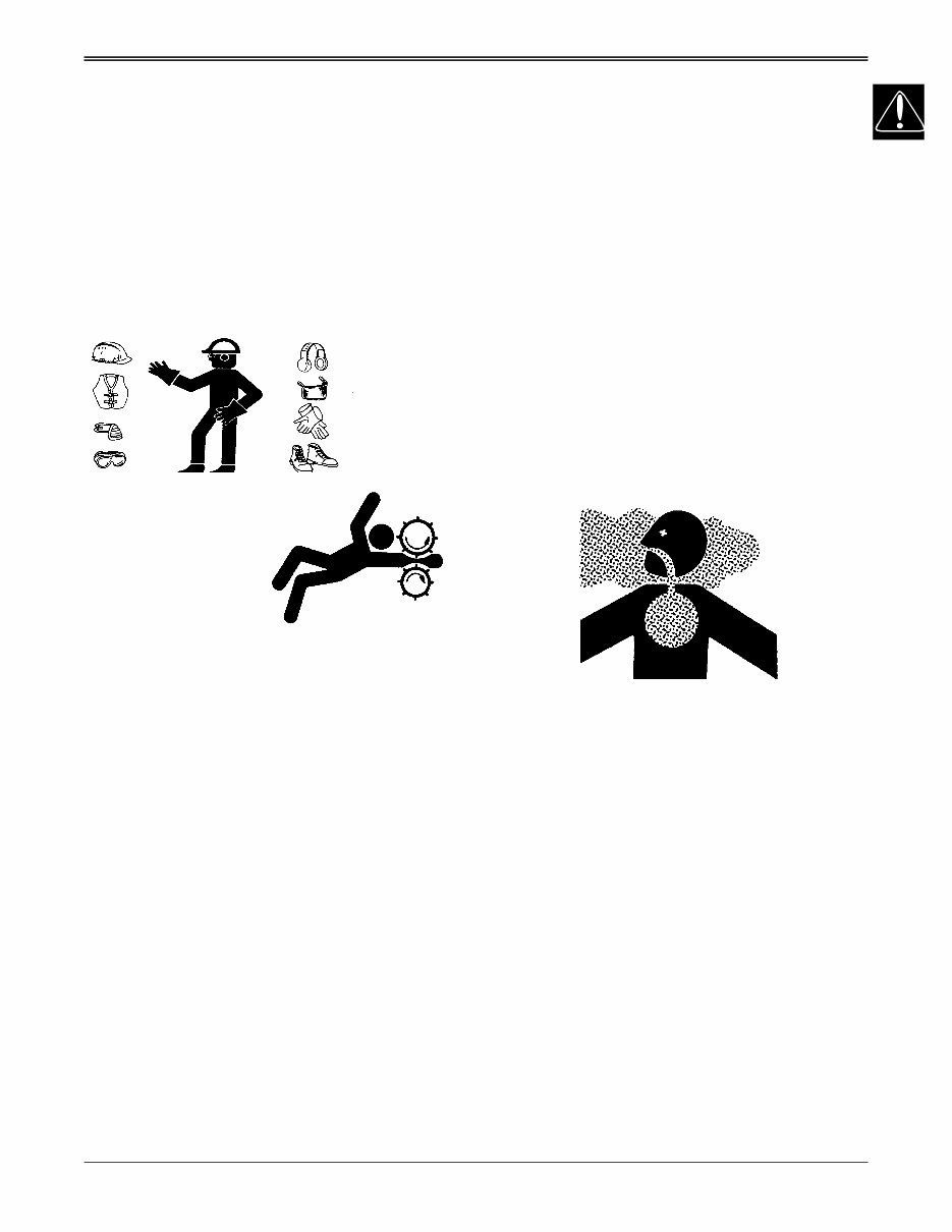
USE SAFE SERVICE PROCEDURES
• WEAR PROTECTIVE CLOTHING
Wear close fitting clothing and safety equipment
appropriate for the job.
Prolonged exposure to loud noise can cause
impairment or loss of hearing. Wear a suitable hearing
protective device such as earmuffs or earplugs to
protect against objectionable or uncomfortable loud
noises.
.
• SERVICE MACHINES SAFELY
Tie long hair behind your head. Do not wear a necktie,
scarf, loose clothing, or necklace when you work near
machine tools or moving parts. If these items were to
get caught, severe injury could result.
Remove rings and other jewelry to prevent electrical
shorts and entanglement in moving parts.
• USE PROPER TOOLS
Use tools appropriate to the work. Makeshift tools and
procedures can create safety hazards. Use power tools
only to loosen threaded parts and fasteners. For
loosening and tightening hardware, use the correct size
tools. DO NOT use U.S. measurement tools on
metric fasteners. Avoid bodily injury caused by slipping
wrenches. Use only service parts meeting John Deere
specifications.
TS228
TS206
• WORK IN CLEAN AREA
• Before starting a job
1. Clean work area and machine:
2. Make sure you have all necessary tools to do your
job.
3. Have the right parts on hand.
4. Read all instructions thoroughly; do not attempt
shortcuts.
• ILLUMINATE WORK AREA SAFELY
Illuminate your work area adequately but safely. Use a
portable safety light for working inside or under the
machine. Make sure the bulb is enclosed by a wire
cage. The hot filament of an accidentally broken bulb
can ignite spilled fuel or oil.
• WORK IN VENTILATED AREA
Engine exhaust fumes can cause sickness or death. If
it is necessary to run an engine in an enclosed area,
remove the exhaust fumes from the area with an
exhaust pipe extension.
If you do not have an exhaust pipe extension, open the
doors and get outside air into the area.
TS220

SAFETY
1 - 4 4/7/95
• REMOVE PAINT BEFORE WELDING OR HEATING
Avoid potentially toxic fumes and dust. Hazardous
fumes can be generated when paint is heated by
welding, soldering, or using a torch. Do all work outside
or in a well ventilated area. Dispose of paint and
solvent properly. Remove paint before welding or
heating: If you sand or grind paint, avoid breathing the
dust. Wear an approved respirator. If you use solvent or
paint stripper, remove stripper with soap and water
before welding. Remove solvent or paint stripper
containers and other flammable material from area.
Allow fumes to disperse at least 15 minutes before
welding or heating.
• AVOID HARMFUL ASBESTOS DUST
Avoid breathing dust that may be generated when
handling components containing asbestos fibers.
Inhaled asbestos fibers may cause lung cancer.
Components in products that may contain asbestos
fibers are brake pads, brake band and lining
assemblies, clutch plates, and some gaskets. The
asbestos used in these components is usually found in
a resin or sealed in some way. Normal handling is not
hazardous as long as airborne dust containing
asbestos is not generated.
Avoid creating dust. Never use compressed air for
cleaning. Avoid brushing or grinding material
containing asbestos. When servicing, wear an
approved respirator. A special vacuum cleaner is
recommended to clean asbestos. If not available, apply
a mist of oil or water on the material containing
asbestos. Keep bystanders away from the area.
REPLACE SAFETY SIGNS
Replace missing or damaged safety signs. See the
machine operator's manual for correct safety sign
placement.
TS201
LIVE WITH SAFETY
Before returning machine to customer, make sure
machine is functioning properly, especially the safety
systems. Install all guards and shields.
TS231

CONTENTS SPECIFICATIONS & INFORMATION
4/7/95 2 - 1
CONTENTS
Page
SPECIFICATIONS & INFORMATION
BASIC ENGINE SPECIFICATIONS . . . . . . . . . . . . . . . . . . . . . . . . . . . . . 3
ENGINE APPLICATIONS . . . . . . . . . . . . . . . . . . . . . . . . . . . . . . . . . . . . . . . . . . . . 3
ENGINE MODEL CONFIGURATION CHANGES . . . . . . . . . . . . . . . . . . . . . . . . . . 4
ENGINE SERIAL NUMBER PLATE LOCATION . . . . . . . . . . . . . . . . . . . . . . . . . . 4
CARBURETOR SERIAL NUMBER LOCATION . . . . . . . . . . . . . . . . . . . . . . . . . . . 5
TEST & ADJUSTMENT SPECIFICATIONS . . . . . . . . . . . . . . . . . . . . . . . 5
REPAIR SPECIFICACATIONS . . . . . . . . . . . . . . . . . . . . . . . . . . . . . . . . 6
FD440V/501V . . . . . . . . . . . . . . . . . . . . . . . . . . . . . . . . . . . . . . . . . . . . . . . . . . . . . 6
FD590V . . . . . . . . . . . . . . . . . . . . . . . . . . . . . . . . . . . . . . . . . . . . . . . . . . . . . . . . . . 9
FD620D . . . . . . . . . . . . . . . . . . . . . . . . . . . . . . . . . . . . . . . . . . . . . . . . . . . . . . . . . 12
METRIC TORQUE VALUES . . . . . . . . . . . . . . . . . . . . . . . . . . . . . . . . . 15
GASOLINE SPECIFICATIONS . . . . . . . . . . . . . . . . . . . . . . . . . . . . . . . 16
FUEL STORAGE . . . . . . . . . . . . . . . . . . . . . . . . . . . . . . . . . . . . . . . . . . . . . . . . . . 16
LUBRICANT SPECIFICATIONS . . . . . . . . . . . . . . . . . . . . . . . . . . . . . . 17
ENGINE OIL . . . . . . . . . . . . . . . . . . . . . . . . . . . . . . . . . . . . . . . . . . . . . . . . . . . . . 17
OIL FILTERS . . . . . . . . . . . . . . . . . . . . . . . . . . . . . . . . . . . . . . . . . . . . . . . . . . . . 17
ENGINE COOLANT . . . . . . . . . . . . . . . . . . . . . . . . . . . . . . . . . . . . . . . . . . . . . . . 17
SYNTHETIC LUBRICANTS . . . . . . . . . . . . . . . . . . . . . . . . . . . . . . . . . . . . . . . . . 17
COMPONENT LOCATION . . . . . . . . . . . . . . . . . . . . . . . . . . . . . . . . . . . 18
FD440V/501V/590V . . . . . . . . . . . . . . . . . . . . . . . . . . . . . . . . . . . . . . . . . . . . . . . 18
INTERNAL ENGINE COMPONENTS . . . . . . . . . . . . . . . . . . . . . . . . . . . . . . . . . . 20
FD620D . . . . . . . . . . . . . . . . . . . . . . . . . . . . . . . . . . . . . . . . . . . . . . . . . . . . . . . . 22

NOTES SPECIFICATIONS & INFORMATION
2 - 2 4/7/95

SPECIFICATIONS & INFORMATION
4/7/95 2 - 3
BASIC ENGINE SPECIFICATIONS
ENGINE APPLICATIONS
NOTE: Refer to the engine application chart to identify product-model/engine type-model relationship.
Lawn Tractors
Machine Engine Model No.
LX178 . . . . . . . . . . . . . . . . . . . . . . . . . . . . . . . . . . . . . . . . . . . . . . . . . . . FD440V - AS00
LX188 . . . . . . . . . . . . . . . . . . . . . . . . . . . . . . . . . . . . . . . . . . . . . . . . . . . FD501V - AS00
Lawn And Garden Tractors
285 Standard . . . . . . . . . . . . . . . . . . . . . . . . . . . . . . . . . . . . . . . . . . . . . FD590V - AS00
285 w/Fuel Injection . . . . . . . . . . . . . . . . . . . . . . . . . . . . . . . . . . . . . . . . FD590V - AS01
320 . . . . . . . . . . . . . . . . . . . . . . . . . . . . . . . . . . . . . . . . . . . . . . . . . . . . FD590V - AS00
425 . . . . . . . . . . . . . . . . . . . . . . . . . . . . . . . . . . . . . . . . . . . . . . . . . . . . . FD620D - AS02
445 . . . . . . . . . . . . . . . . . . . . . . . . . . . . . . . . . . . . . . . . . . . . . . . . . . . . . FD620D - AS01
Front Mowers
F911 . . . . . . . . . . . . . . . . . . . . . . . . . . . . . . . . . . . . . . . . . . . . . . . . . . . . FD620D - AS00
F725 . . . . . . . . . . . . . . . . . . . . . . . . . . . . . . . . . . . . . . . . . . . . . . . . . . . . FD590V - AS03
Golf And Turf Equipment
1800 Utility Vehicle . . . . . . . . . . . . . . . . . . . . . . . . . . . . . . . . . . . . . . . . . FD620D - AS04
2243 Professional Greensmower . . . . . . . . . . . . . . . . . . . . . . . . . . . . . FD590V - AS02
2653 Professional Utility Mower . . . . . . . . . . . . . . . . . . . . . . . . . . . . . . . FD620D - AS04
6X4 Gator Utility Vehicles . . . . . . . . . . . . . . . . . . . . . . . . . . . . . . . . . . . . FD620D - AS11
ENGINE
FD440V
AS00
FD501V
AS00
FD590V-
AS00/02
FD590V-
AS03
FD620D
AS04/11
FD620D
ASO2
FD620D
AS00/01
HORSEPOWER 11.1 kW
(15 HP)
12.6kW
(17 HP)
13.4 kW
(18 HP)
14.9kW (20
HP)
13.4 kW
(18 HP)
14.9kW
(20 HP)
16.4 kW
(22 HP)
CYLINDER 2 2 2 2 2 2 2
CYCLE 4 4 4 4 4 4 4
BORE 67 mm
(2.64 in.)
67 mm
(2.64 in.)
74 mm
(2.90 in.)
74 mm
(2.90 in.)
76 mm
(2.99 in.)
76 mm
(2.99 in.
76 mm
(2.99 in.
STROKE 62 mm
(2.44 in.)
62 mm
(2.44 in.)
68 mm
(2.66 in.)
68 mm
(2.66 in.)
68 mm
(2.66 in.)
68 mm
(2.66 in.)
68 mm
(2.66 in.)
DISPLACEMENT
437 cm
3
(26.7 cu.
in.)
437 cm
3
(26.7 cu.
in.)
585 cm
3
(35.7 cu.
in.)
585 cm
3
(35.7 cu.
in.)
617 cm
3
(35.7 cu.
in.)
617 cm
3
(35.7 cu.
in.)
617 cm
3
(35.7 cu.
in.)
SPECIFICATIONS & INFORMATION
2 - 4 4/7/95
ENGINE MODEL CONFIGURATION
CHANGES
FD590V
The following is a list of the major differences between
the model configurations of the FD590V-AS00 through
the FD590V-AS03.
• The FD590V-AS00 is the first configuration used and
its first application was in the 285 Lawn and Garden
Tractor.
• FD590V-AS01 was converted to a electronic fuel
injection system. The carburetor was replaced by a
throttle body and a water temperature sensor was
added.
• FD590V-AS02 engine is used in the 2243 Triplex
Professional Greensmower.
• FD590V-AS03 is used in the F725 Front Mower. The
power was increased from 18 to 20 horsepower. To
obtain the higher horsepower the following
components were changed:
• A larger redesigned intake manifold
• The cylinder head induction passage and combustion
chamber was redesigned.
• A larger carburetor is used.
NOTE: The FD440V, FD501V and FD590V are vertical
shaft engines. The FD620D is a horizontal shaft
engine.
FD620D
The differences in horsepower are due to the following:
• rpm that the engine must run for the application.
• the efficiencies of fuel injection on the FD620 - AS01.
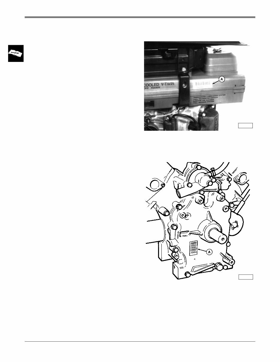
ENGINE SERIAL NUMBER PLATE
LOCATIONS
NOTE: Refer to the engine model designation on the
engine serial number plate to identify repair
information covered in the Component Technical
Manual
FD440V/FD501V/FD590V:
The engine serial number (A) is located on the side of
the cooling air duct.
FD620D:
The engine serial number (A) is located on the
crankcase cover.
M53952
M53953
TEST & ADJUSTMENT SPECIFICATIONS SPECIFICATIONS & INFORMATION
4/7/95 2 - 5
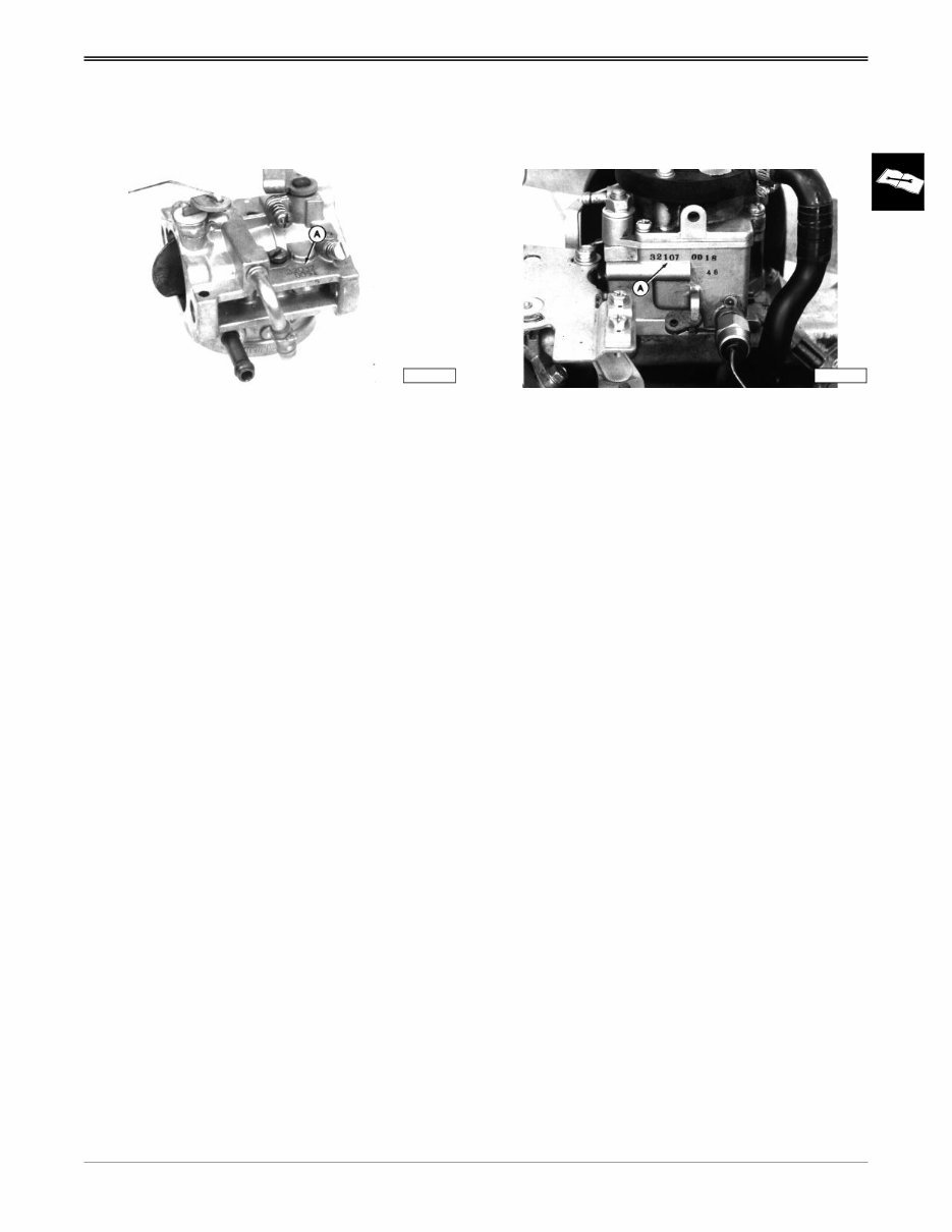
CARBURETOR SERIAL NUMBER
LOCATIONS
FD440V/FD501V/FD590V:
The carburetor serial number (A) is located on the top
of carburetor.
M53957
FD620D:
The carburetor serial number (A) is located on the side
of carburetor.
M53958
TEST & ADJUSTMENT SPECIFICATIONS
Engine:
Oil pressure sensor activates . . . . . . . . . . . . . . . . . . . . . . . . . . . . . . . . 98 kPa (14.2 psi)
Oil pressure (minimum) . . . . . . . . . . . . . . . . . . . . . . . . . . . . . . . . . . . . . 276 kPa (40 psi)
Oil filter bypass valve opening pressure . . . . . . . . . . . 78.5—117.5 kPa (11.4—17.1 psi)
Cylinder compression pressure (minimum) . . . . . . . . . . . . . . . . . . . . 1171 kPa (170 psi)
Maximum compression pressure variation between cylinders . . . . . . . . 138 kPa (20 psi)
Crankcase vacuum (minimum) . . . . . . . . . . . . . . . . . . . . . . . . . . . . . 25 mm (1 in.) water
Intake and exhaust valve clearance (cold) . . . . . . . . . . . . . . . . . . . . . 0.25 mm (0.01 in.)
Intake and exhaust valve adjustment interval . . . . . . . . . . . . . . . . . . . . . . . . . . . 300 hrs.
Valve clearance adjusting nut torque . . . . . . . . . . . . . . . . . . . . . . . . . . . 9 N•m (79 lb-in)
Fuel/Air System:
Fuel Pump
Minimum flow . . . . . . . . . . . . . . . . . . . . . . . . . . . . . . . . . 105 ml (3.5 oz) in 15 seconds
Minimum pressure . . . . . . . . . . . . . . . . . . . . . . . . . . . . . . . . . . . . . . . . 10 kPa (1.5 psi)
Carburetor SLOW idle mixture screw initial setting . . . . . . . . . . . . . . . . . . . . . . . . . 1 Turn
Carburetor SLOW idle stop screw setting
. . . . . . . . . . . . . . . 50 rpm less than throttle control arm SLOW idle stop screw setting
Throttle Cable Throttle control arm SLOW idle stop screw setting
. . . . . . . . . . . . . . . . . . . . . . . . . . . . . . . . . . . . . . . . . . . . . . . . . . . . . 1175+25 / -50 rpm
Throttle control arm FAST idle stop screw setting . . . . . . . . . . . . . . . . . . 3650 ± 75 rpm
Air Restriction Indicator
Normal restriction vacuum . . . . . . . . . . . . . . . . . . . . . . . . . . . .102—178 mm (4—7 in.)
Maximum restriction vacuum . . . . . . . . . . . . . . . . . . . . . . . . . . . . . . . . 381 mm (15 in.)
Fuel Tank
Check valve opening pressure (maximum) . . . . . . . . . . . . . . . . . . . . . . 3 kPa (0.4 psi)
Cooling System:
Radiator cap
Maximum test pressure . . . . . . . . . . . . . . . . . . . . . . . . . . . . . . . . . . . . 117 kPa (17 psi)
Minimum pressure after 15 seconds . . . . . . . . . . . . . . . . . . . . . . . . . . . 90 kPa (13 psi)
Opening pressure. . . . . . . . . . . . . . . . . . . . . . . . . . . . . . . . . . . . 83–96 kPa (12–14 psi)
Minimum pressure . . . . . . . . . . . . . . . . . . . . . . . . . . . . . . . . . . . . . . . . . 76 kPa (11 psi)
Thermostat
Begin-to-open temperature . . . . . . . . . . . . . . . . . . . . . . . approximately 63°C (145°F)
Full-open temperature . . . . . . . . . . . . . . . . . . . . . . . . . . . approximately 80°C (176°F)
Full-closed temperature . . . . . . . . . . . . . . . . . . . . . . . . . . approximately 63°C (145°F)
You're Reading a Preview
What's Included?
Fast Download Speeds
Online & Offline Access
Access PDF Contents & Bookmarks
Full Search Facility
Print one or all pages of your manual
$35.99
JD K Series LIQUID-COOLED Engine Workshop Service Manual
Viewed 87 Times Today

What's Included?
Fast Download Speeds
Online & Offline Access
Access PDF Contents & Bookmarks
Full Search Facility
Print one or all pages of your manual
$35.99

Secure transaction
What's Included?
Fast Download Speeds
Online & Offline Access
Access PDF Contents & Bookmarks
Full Search Facility
Print one or all pages of your manual
Description
Get access to a comprehensive workshop service repair manual for JOHN DEERE K SERIES LIQUID-COOLED ENGINE. This manual covers a range of engine models including 437cc 15HP FD440V (AS00), 437cc 17HP FD501V (AS00), 585cc 20HP FD590V (AS03), 617cc 20HP FD620D (ASO2), 585cc 18HP FD590V (AS00/02), 617cc 18HP FD620D (AS04/11), and 617cc 22HP FD620D (AS00/01).
- General information
- Specifications
- Tightening torque
- Engine application
- Engine fuel system
- Air cleaner system
- Carburetor system
- Fuel injection system
- Recoil starter
- Governor system
- Electric starter
- Blower housing system
- Flywheel & cylinder head
- Cylinder block & valves
- Internal components
- Piston-piston rings
- Crankshaft-connecting rod
- Ignition system
- Charging system
- Starting system
- Breather system
- Fuel pump system
- Essential tools intake system
- Muffler system
- Lubrication system
- Cooling system
- Electrical system
- Troubleshooting
This manual features detailed exploded views, step-by-step procedures with illustrations, and is fully printable. It is an essential resource for both professional mechanics and DIY enthusiasts for repairs, maintenance, and servicing of JOHN DEERE K SERIES LIQUID-COOLED ENGINES.


