

POWERTECH 13.5 L 6135HF485/HF475 Operators Manual
What's Included?
Fast Download Speeds
Online & Offline Access
Access PDF Contents & Bookmarks
Full Search Facility
Print one or all pages of your manual
POWERTECH™
13.5 L OEM
6135HF485/HF475 Emis
sions Diesel Engines
OPERATOR’S MANUAL
13.5 L OEM 6135HF485/HF475
Emissions Diesel Engines
OMRG36873 ISSUE 16DEC10 (ENGLISH)
CALIFORNIA
Proposition 65 Warning
Diesel engine exhaust and some of its constituents
are known to the State of California to cause cancer,
birth defects, and other reproductive harm.
If this product contains a gasoline engine:
WARNING
The engine exhaust from this product contains
chemicals known to the State of California to cause
cancer, birth defects or other reproductive harm.
The State of California requires the above two warnings.
Additional Proposition 65 Warnings can be found in this manual.
John Deere Power Systems
LITHO IN U.S.A.

Introduction
JR74534,00002EA 1916DEC101/1
Foreword
READ THIS MANUAL carefully to learn how to operate
and service your engine correctly. Failure to do so could
result in personal injury or equipment damage.
THIS MANUAL SHOULD BE CONSIDERED a permanent
part of your engine and should remain with the engine
when you sell it.
MEASUREMENTS IN THIS MANUAL are given in both
metric and customary U.S. unit equivalents. Use only
correct replacement parts and fasteners. Metric and inch
fasteners may require a specific metric or inch wrench.
RIGHTHAND AND LEFTHAND sides are determined by
standing at the drive or flywheel end (rear) of the engine
and facing toward the front of the engine.
WRITE ENGINE SERIAL NUMBERS and option codes
in the spaces indicated in the Record Keeping section.
Accurately record all the numbers. Your dealer also
needs these numbers when you order parts. File the
identification numbers in a secure place off the engine.
SETTING FUEL DELIVERY beyond published factory
specifications or otherwise overpowering will result in loss
of warranty protection for this engine.
CERTAIN ENGINE ACCESSORIES such as radiator,
air cleaner, and instruments are optional equipment on
John Deere OEM Engines. These accessories may be
provided by the equipment manufacturer instead of John
Deere. This operator’s manual applies only to the engine
and those options available through the John Deere
distribution network.
NOTE: This operator’s manual covers only engines
provided to OEM (Original Equipment
Manufacturers). For engines in Deere machines,
refer to the machine operator’s manual.
This manual covers primarily the PowerTech Plus 13.5
L (6135HF485) OEM engines. These engines meet
emission standards for EPA Tier 3 and EU Stage III A.
010311
PN=2

Introduction
OURGP11,0000251 1918SEP071/1
Engine Owner
John Deere Engine Owner:
Don’t wait until you need warranty or other service
to meet your local John Deere Engine Distributor
or Service Dealer. To register your engine for
warranty via the Internet, use the following URL:
http://www.johndeere.com/enginewarranty
Learn who your dealer is and where he is. At your first
convenience, go meet him. He’ll want to get to know you
and to learn what your needs might be.
Aux Utilisateurs De Moteurs John Deere:
N’attendez pas d’être obligé d’avoir recours à votre
concessionnaire John Deere ou au point de service le plus
proche pour vous adresser à lui. Pour enregistrer votre
moteur pour la garantie via Internet, utilisez l’adresse
suivante: http://www.johndeere.com/enginewarranty
Renseignezvous dès que possible pour l’identifier et le
localiser. A la première occasion, prenez contact avec lui
et faitesvous connaître. Il sera lui aussi heureux de faire
votre connaissance et de vous proposer ses services le
moment venu.
An Den Besitzer Des John Deere Motors:
Warten Sie nicht auf einen evt. Reparaturfall,
um den nächstgelegenen John Deere Händler
kennen zu lernen. Zur Registrierung Ihres Motors
für die Garantie dient folgende InternetAdresse:
http://www.johndeere.com/enginewarranty
Machen Sie sich bei ihm bekannt und nutzen Sie sein
“Service Angebot”.
Proprietario del motore John Deere:
Non aspetti fino al momento di far valere la garanzia
o di chiedere assistenza per fare la conoscenza del
distributore dei motori John Deere o del concessionario
che fornisce l’assistenza tecnica. Per registrare via
Internet la garanzia del suo motore, si collegi al seguente
sito URL: http://www.johndeere.com/enginewarranty
Lo identifichi e si informi sulla sua ubicazione. Alla
prima occasione utile lo contatti. Egli desidera fare la
sua conoscenza e capire quali potrebbero essere le sue
necessità.
Propietario De Equipo John Deere:
No espere hasta necesitar servicio de garantía o de otro
tipo para conocer a su Distribuidor de Motores John
Deere o al Concesionario de Servicio. Registre su motor
para la garantía en la siguiente dirección de internet:
http://www.johndeere.com/enginewarranty
Aprenda quién es su distribuidor y donde él está situado.
Cuando tenga un momento, vaya a visitarlo. A él le
gustará conocerlo, y saber cuáles podrían ser sus
necesidades.
Till ägare av John Deere motorer:
Ta reda på vem din återförsäljare är och besök honom så
snart tillfälle ges. Vänta inte tills det är dags för service eller
eventuellt garantiarbete. Din motor garantiregistrerar Du
via Internet på http://www.johndeere.com/enginewarranty
Din återförsäljare vill mycket gärna träffa dig för att lära
känna dina behov och hur bäst han kan hjälpa dig.
010311
PN=3
Introduction
OMRGP15,000011D 1912SEP061/1
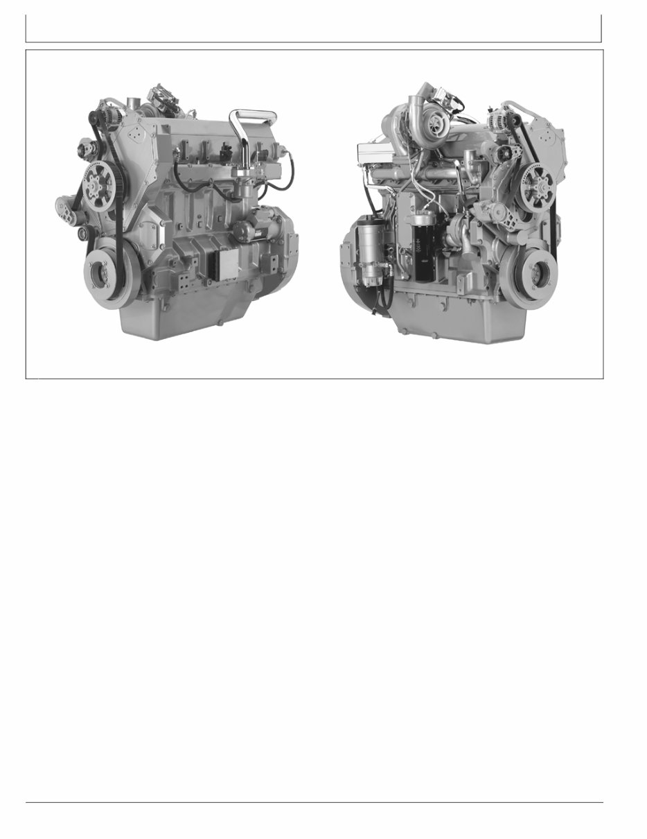
Engine Identification Views
RG13885 —UN—19MAY05
13.5L Engine Left Front View
RG13886 —UN—19MAY05
13.5L Engine Right Front View
010311
PN=4

Contents
Page
Record Keeping
Record Engine Serial Number ............................ 011
Engine Option Codes ......................................... 012
Record Engine Control Unit (ECU)
Serial Number ................................................ 013
Record Rear Power TakeOff (PTO)
Serial Number (If Equipped)........................... 014
Safety .......................................................... 051
Fuels, Lubricants, and Coolant
Diesel Fuel.......................................................... 101
Lubricity of Diesel Fuel ....................................... 101
Handling and Storing Diesel Fuel ....................... 102
Testing Diesel Fuel ............................................. 102
Biodiesel Fuel ..................................................... 103
Minimizing the Effect of Cold Weather
on Diesel Engines .......................................... 104
Diesel Engine BreakIn Oil ................................. 105
Diesel Engine Oil ................................................ 106
Diesel Engine Oil and Filter Service Intervals .... 107
Mixing of Lubricants............................................ 108
OILSCAN ™ and COOLSCAN ™ ...................... 109
Alternative and Synthetic Lubricants .................. 109
Lubricant Storage ............................................... 109
Oil Filters .......................................................... 1010
Heavy Duty Diesel Engine Coolant .................. 1010
Supplemental Coolant Additives....................... 1011
Drain Intervals for Diesel Engine Coolant......... 1011
Additional Information About Diesel
Engine Coolants and John Deere
LIQUID COOLANT CONDITIONER............. 1012
Testing Diesel Engine Coolant.......................... 1013
Operating in Warm Temperature Climates ....... 1013
Disposing of Coolant ........................................ 1014
Instrument Panel and Diagnostic Gauge
Instrument Panels............................................... 151
Using Diagnostic Gauge to Access
Engine Information ......................................... 153
Main Menu Navigation ........................................ 153
Engine Configuration Data ................................. 155
Accessing Stored Trouble Codes ....................... 157
Accessing Active Trouble Codes ........................ 159
Engine Shutdown Codes .................................. 1511
Adjusting Backlighting ...................................... 1512
Page
Adjusting Contrast ............................................ 1514
Selecting Units Of Measurement ...................... 1515
Setup 1Up Display........................................... 1517
Setup 4Up Display........................................... 1523
Engine Operation
Engine BreakIn Service ..................................... 201
Auxiliary Gear Drive Limitations ......................... 203
Generator Set (Standby) Applications ................ 203
Starting the Engine ............................................. 204
Restarting Engine Which Has Run Out
Of Fuel ........................................................... 205
Warming Engine ................................................. 206
Normal Engine Operation ................................... 206
Cold Weather Operation ..................................... 207
Changing Engine Speed..................................... 208
Avoid Excessive Engine Idling............................ 209
Stopping the Engine ......................................... 2010
Using a Booster Battery or Charger ................. 2011
Lubrication and Maintenance
Observe Service Intervals .................................. 251
Use Correct Fuels, Lubricants, and Coolant....... 251
Lubrication and Maintenance Service
Interval Chart—Industrial Unit and
Generator (Prime Power) ............................... 252
Lubrication and Maintenance Service
Interval Chart—Generator (Standby)
Applications .................................................... 253
Lubrication and Maintenance/Daily
Daily Prestarting Checks .................................... 301
Lubrication & Maintenance/500 Hour/12 Month
Servicing Fire Extinguisher ................................. 351
Servicing Battery ................................................ 351
Changing Engine Oil and Replacing Oil Filter .... 353
Visually Inspecting Coolant Pump ...................... 355
Replacing Fuel Filters/Cleaning Water
Separator (Earlier Engines)............................ 355
Replacing Fuel Filters/Cleaning Water
Separator (Later Engines) .............................. 359
Checking and Adjusting Engine Speeds .......... 3511
Checking Engine Mounts.................................. 3511
Checking Crankcase Vent Tube and Valve ...... 3511
Checking Air Intake System ............................. 3512
Continued on next page
Original Instructions. All information, illustrations and specifications in this
manual are based on the latest information available at the time of publication.
The right is reserved to make changes at any time without notice.
COPYRIGHT © 2010
DEERE & COMPANY
Moline, Illinois
All rights reserved.
A John Deere ILLUSTRUCTION ® Manual
Previous Editions
Copyright © 2005, 2006, 2008, 2009
i
010311
PN=1

Contents
Page
Check Engine Electrical Ground Connection ...3512
Checking Belt Tensioner Spring
Tension and Belt Wear ................................. 3513
Checking Cooling System ................................ 3514
Testing Diesel Engine Coolant.......................... 3515
Replenishing Supplemental Coolant
Additives (SCAs) Between Coolant
Changes ....................................................... 3516
Pressure Testing Cooling System..................... 3517
Lubrication & Maintenance/2000 Hr/24 Month
Checking Crankshaft Vibration Damper ............. 401
Flushing and Refilling Cooling System ............... 402
Testing Thermostats Opening Temperature ....... 405
Lubrication and Maintenance/2500 Hour
Checking and Adjusting Engine Valve
Clearance and Electronic Unit
Injector Preload .............................................. 451
Do Not Modify Fuel System................................ 451
Service as Required
Additional Service Information ............................ 501
Adding Coolant ................................................... 501
Replacing Air Cleaner Filter Elements................ 502
Draining Fuel Filter Water Separator Bowl ......... 503
Bleeding Fuel System (Earlier Engines) ............. 504
Bleeding Fuel System (Later Engines) ............... 504
Replacing Fan/Alternator VBelts ....................... 505
VBelt Routing .................................................... 506
Checking Fuses .................................................. 506
Air Compressors ................................................. 506
Rear Power TakeOff (PTO) ............................... 507
Troubleshooting
General Troubleshooting Information ................. 551
Instrument Panel Method for Retrieving
Diagnostic Trouble Codes .............................. 552
Displaying Of Diagnostic Trouble
Codes (DTCs) ................................................ 552
Listing of Diagnostic Trouble Codes (DTCs) ...... 553
Intermittent Fault Diagnostics ............................. 558
Displaying Diagnostic Gauge Software .............. 558
Engine Troubleshooting.................................... 5510
Engine Troubleshooting (Continued) ................ 5512
Electrical Troubleshooting ................................ 5514
Lubrication System Troubleshooting ................ 5516
Cooling System Troubleshooting...................... 5519
Air Intake and Exhaust System
Troubleshooting............................................ 5521
Low Pressure Fuel System Troubleshooting .... 5523
Electrical System Layout .................................. 5524
Electrical System Layout Continued................ 5525
Precautions for Welding on Vehicles
Equipped with Electronic Engine
Control Unit (ECU) ....................................... 5526
Precautions for Electrical System
When Steam Cleaning Engine ..................... 5526
Page
Engine Wiring Diagram (Engines With
FullFeatured Instrument Panel) .................. 5527
Engine Wiring Diagram (Engines With
FullFeatured Instrument Panel)
(Continued) .................................................. 5528
Engine Wiring Diagram (Engines With
FullFeatured Instrument Panel)
(Continued) .................................................. 5529
Storage
Engine Storage Guidelines ................................. 601
Preparing Engine for Long Term Storage ........... 601
Removing Engine from Long Term Storage ....... 602
Specifications
General OEM Engine Specifications .................. 651
Engine Power Ratings And Fuel System
Specifications ..................................................... 653
Engine Crankcase Oil Fill Quantities .................. 654
Unified Inch Bolt and Screw Torque Values........ 655
Metric Bolt and Screw Torque Values ................. 656
Lubrication and Maintenance Records
Using Lubrication and Maintenance Records ..... 701
Daily (Prestarting) Service .................................. 701
500 Hours of Operation/or 12 Months Service ...701
2000 Hours of Operation/or 24 Months
Service ........................................................... 702
2500 Hours of Operation Service ....................... 702
Service as Required ........................................... 702
Emission System Warranty
U.S. EPA Emissions Control Warranty
Statement ....................................................... 751
Emissions Control System Certification Label .... 751
Technical Information.......................................... 752
ii
010311
PN=2
Record Keeping
OURGP11,000004B 1912SEP061/1
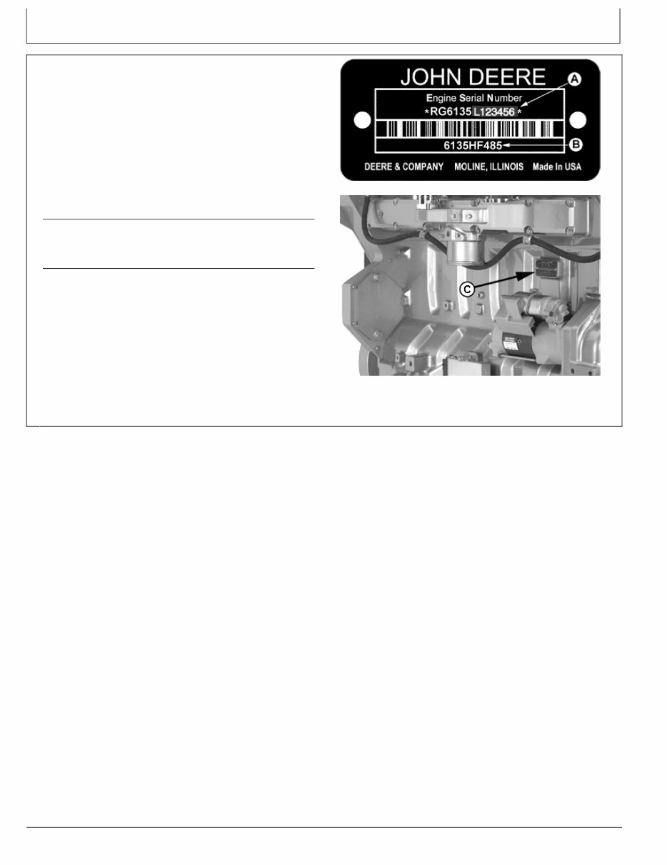
Record Engine Serial Number
The engine serial number plate (C) is located on the
lefthand side of engine block between intake manifold
and starter motor.
Record all of the numbers and letters found on your
engine serial number plate in the spaces provided below.
This information is very important for repair parts or
warranty information.
Engine Serial Number (A)
Engine Model Number (B)
NOTE: On engine serial number (A) the 7th digit
shows the emission level as follows:
• “B” for noncertified engines
• “C” for Tier 1 / Stage I engines
• “G” for Tier 2 / Stage II engines
• “L” for Tier 3 / Stage IIIA engines
A—Engine Serial Number
B—Engine Model Number
C—Engine Serial Number Plate
RG14798 —UN—23JUN06
Engine Serial Number/Application Data
RG13887 —UN—26JUL05
Location of Engine Serial Number Plate
011
010311
PN=7
Record Keeping
Continued on next page OURGP11,000007F 1911OCT061/2
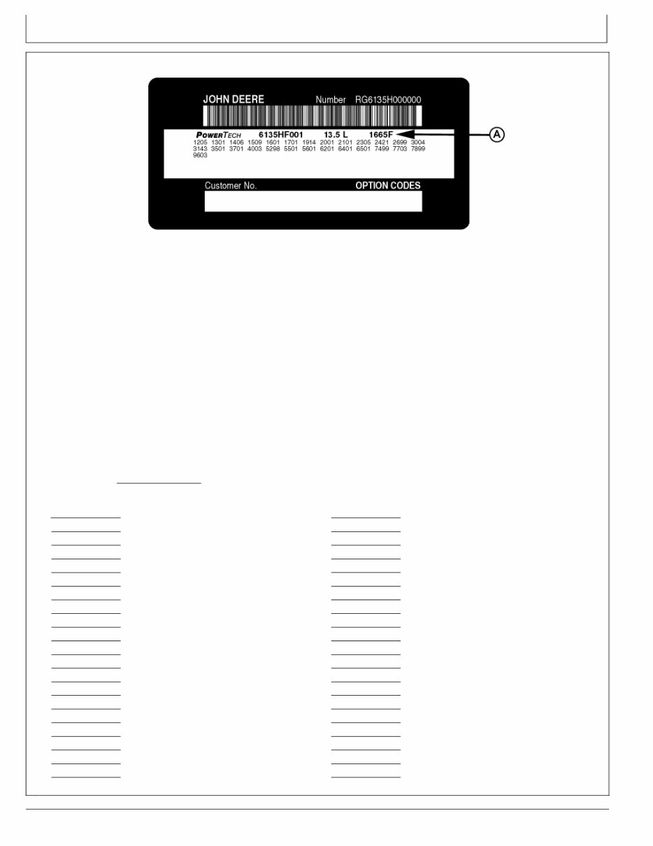
Engine Option Codes
RG13880 —UN—06JUL05
Option Code Label
A—Base Engine Code
NOTE: Your engine option code label may not contain
all option codes if an option has been added after
the engine left the producing factory.
If option label is lost or destroyed, consult your
servicing dealer or engine distributor selling
the engine for a replacement.
In addition to the serial number plate, OEM engines have
an engine option code label affixed to the valve cover.
These codes indicate which of the engine options were
installed on your engine at the factory. When in need of
parts or service, furnish your authorized servicing dealer
or engine distributor with these numbers.
The engine option code label includes an base engine
code (A) (1665F, bold print in label above). Record this
code along with option codes on following page.
The first two digits of each code identify a specific group,
such as alternators. The last two digits of each code
identify one specific option provided on your engine, such
as a 24volt, 60amp alternator.
If an engine is ordered without a particular component, the
last two digits of that functional group option code will be
99, 00, or XX. The list on the next page shows only the
first two digits of the code numbers. For future reference,
such as ordering repair parts, it is important to have these
code numbers available. To ensure this availability, enter
the third and fourth digits shown on your engine option
code label in the spaces provided on the following page.
Base Engine Code (See “A” on previous page.)
Option Codes Description Option Codes Description
11 Valve Cover 51 Cylinder Head With Valves
12 Oil Fill Inlet 52 Auxiliary Gear Drive
13 Crankshaft Pulley/Damper 53 Fuel Heater
14 Flywheel Housing 54 Air Intake for Turbocharger
15 Flywheel 55 Shipping Stand
16 Fuel Injection Pump 56 Paint Option
17 Air Inlet 57 Coolant Pump Inlet
18 Air Cleaner 59 Oil Cooler
19 Oil Pan 60 Addon Auxiliary Drive Pulley
20 Coolant Pump 62 Alternator Mounting Bracket
21 Thermostat Cover 63 Low Pressure Fuel Line
22 Thermostat 64 Exhaust Elbow
23 Fan Drive 65 Turbocharger
24 Fan Belt 66 Coolant Temperature Switch
25 Fan 67 Electronic Sensors (Base Engine)
26 Engine Coolant Heater 68 Crankshaft Rear Damper
27 Radiator 69 Engine Serial Number Plate
28 Exhaust Manifold 71 Engine Oil Bypass Filter
29 Crankcase Ventilator System 72 ECU Electronic Software Option
30 Starter Motor 74 Air Conditioning (Freon) Compressor
012
010311
PN=8
Record Keeping
OURGP11,000007F 1911OCT062/2
OURGP12,0000125 1912SEP061/1
Option Codes Description Option Codes Description
31 Alternator 75 Air Restriction Indicator
32 Instrument Panel 76 Pressure Switches and Sensors
33 Tachometer 77 Timing Gear Cover
35 Fuel Filters 78 Air Compressor
36 Front Plate 79 Engine Certification
37 Fuel Transfer Pump 81 Primary Fuel Filter And Water Separator
39 Thermostat Housing 83 Electronic Software (Vehicle Option)
40 Oil Dipstick 84 Electrical Wiring Harness
41 BeltDriven Front Auxiliary Drive 86 Fan Pulley
43 Starting Aid 87 Belt Tensioner
44 Timing Gear Cover With Gears 88 Oil Filter
45 Balancer Shafts 89 Exhaust Gas Recirculating (EGR) System
46 Cylinder Block With Liners and Camshaft 95 Special Equipment (Factory Installed)
47 Crankshaft and Bearings 96 Engine Installation Kit
48 Connecting Rods and Pistons 97 Special Equipment (Field Installed)
49 Valve Actuating Mechanism 98 Shipping (Engine Hanger Straps)
50 Oil Pump 99 Service Only Items
NOTE: These option codes are based on the latest
information available at the time of publication.
The right is reserved to make changes at
any time without notice.
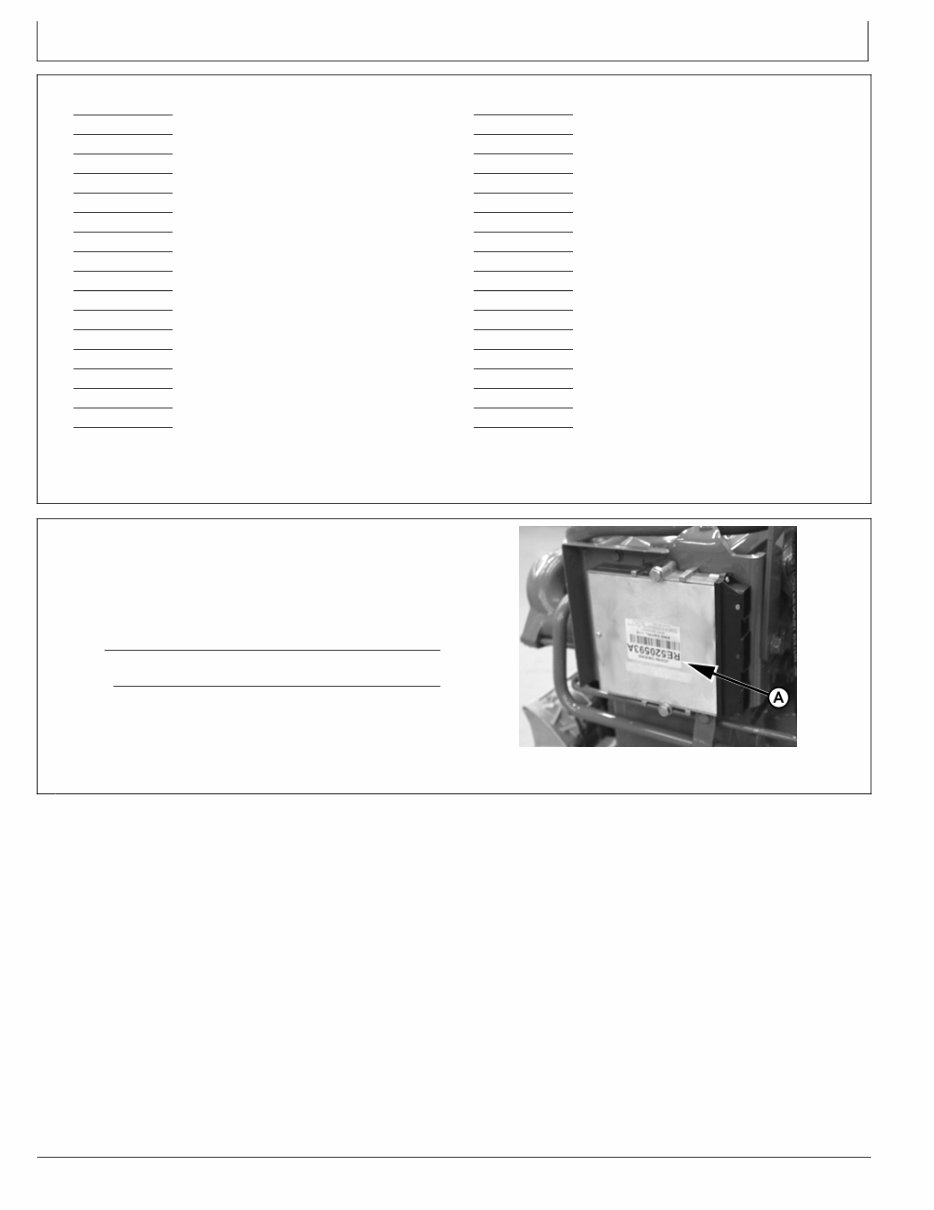
Record Engine Control Unit (ECU) Serial
Number
Record the part number and serial number information
found on the serial number label (A) on the Engine Control
Unit (ECU) mounted on or near the engine.
Part No.
Serial No.
A—Serial Number Label
RG13891 —UN—14JUN05
Record Engine Control Unit (ECU) Serial Number
013
010311
PN=9
Record Keeping
OUOD006,0000066 1912SEP061/1
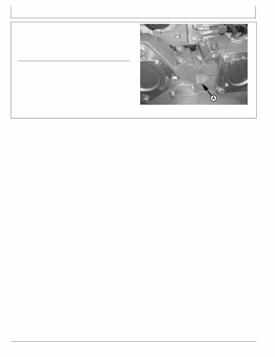
Record Rear Power TakeOff (PTO) Serial
Number (If Equipped)
Record the rear power takeoff (PTO) serial number found
on rear PTO serial number plate (A) (if equipped).
Rear PTO Serial Number
RG12594 —UN—24SEP02
Rear PTO Serial Number Plate
014
010311
PN=10
You're Reading a Preview
What's Included?
Fast Download Speeds
Online & Offline Access
Access PDF Contents & Bookmarks
Full Search Facility
Print one or all pages of your manual
$33.99
Viewed 90 Times Today


Secure transaction
What's Included?
Fast Download Speeds
Online & Offline Access
Access PDF Contents & Bookmarks
Full Search Facility
Print one or all pages of your manual
$33.99
Get the comprehensive 13.5 L 6135HF485/HF475 Operators Manual for Emissions Diesel Engines. This manual is an invaluable resource for both professional mechanics and DIY enthusiasts. It is available in English and consists of 161 pages. The manual is compatible with both Windows and MAC platforms.


