

Isuzu AU-4LE2, BV-4LE2 Diesel Engine Service Repair Workshop Manual
What's Included?
Fast Download Speeds
Online & Offline Access
Access PDF Contents & Bookmarks
Full Search Facility
Print one or all pages of your manual
AU-4LE2
BV-4LE2
MODEL

General Information 0A-1
General Information
General Information
Table of Contents
General Information .............................................. 0A-2
Service Precautions ........................................... 0A-2
Reading the Model ............................................. 0A-7
General Information ........................................... 0A-8
Recommended Lubricant ................................. 0A-14
List of Trouble Symptom .................................. 0A-15
Repair Standard ............................................... 0A-24
0A-2 General Information
General Information
Service Precautions
In order to carry out work safely
1. Always use an engine stand when taking the
engine down from the vehicle.
Do not place the engine directly onto the ground,
or place in a manner that interferes with the oil
pan.
2. If you are working together with others, always pay
attention to each other's safety.
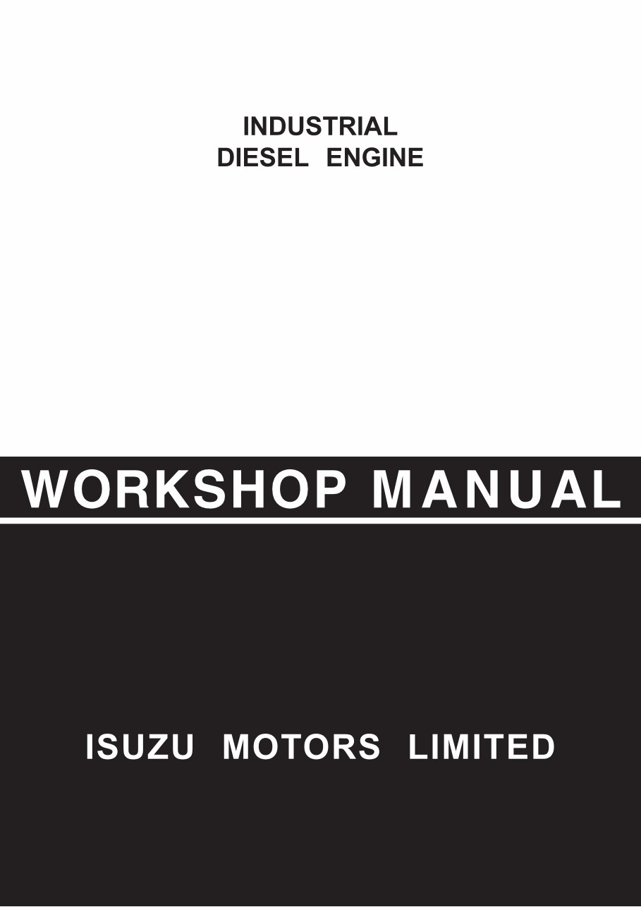
3. If you are repairing any part of the electrical sys-
tem, always remove the minus side cable from the
battery terminal before starting work. If you are
removing the battery cover, always remove the
cover in a place that is away from sources of fire/
heat.
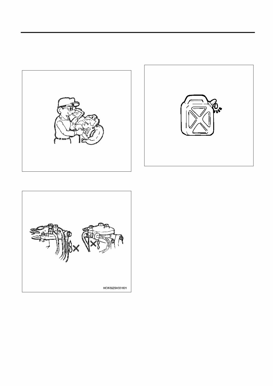
4. Do not perform painting work or leave the engine
running for long periods of time in an enclosed or
badly ventilated indoor workshop.
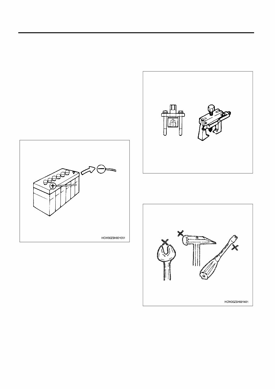
5. Always use the correct specialized tool indicated in
the instructions. Using the incorrect tool may
cause damage to the parts or injury to the person
using the tool.
6. All regular tools, gauges and special tools should
be regularly inspected, and prepared before start-
ing work. Do not use bent spanners, hammers with
damaged edges, chipped chisels, or any other
faulty or damaged tools.
WSHK0190
General Information 0A-3
7. Always pay close attention to safety and handling
requirements when using grinders, cranes, weld-
ers, and other such equipment.
Moreover, always wear the correct protective gar-
ments and use the necessary safety tools for the
job in hand.
8. Always check that there are no fuel leaks when
performing maintenance work on the fuel system.
(It may cause a fire.)
9. Pay close attention to the risk of ignition if you are
handling parts that carry a high voltage.
Furthermore, any oil or grease spilt onto rubber
parts must be wiped off immediately, as it will
cause deterioration of the rubber.
Replacement parts and part numbers
1. Always replace packing, oil seals, O-rings, caulk-
ing lock nuts, folding lock plates, split pins and
other such parts with brand new parts.
2. The parts numbers contained in this manual may
not represent the supply condition of the parts, and
the part numbers may be changed due to revi-
sions. Therefore, parts should always be checked
against a parts catalogue before use.
WSHK0191
WSHK0192

0A-4 General Information
Liquid gasket
1. Each time you disassemble parts that use liquid
gasket, completely remove the old gasket residue
from each of the parts and matching sections using
a scraper, then clean each of the parts to com-
pletely remove oil, water, and dirt etc. from the var-
ious surfaces by a cloth. Using the specified type
of liquid gasket, apply new liquid gasket to each of
the surfaces before reassembling the parts.
2. In order to make it easier to clean liquid gasket sur-
faces, apply gasket remover liquid (Pando- 391D
made by ThreeBond Co., Ltd.) and leave the part
to stand for approximately 10 minutes, after which
the old liquid gasket residue will be easier to
remove.
However, this should not be used on resin compo-
nents or painted components.
3. Please take care not to apply too much or too little
liquid gasket.
Also, you should always re-apply the liquid gasket
upon itself when you start and finish application.
4. Make sure that there are no gaps when reinstalling
the liquid gasket parts to each other. If there are
gaps between the two parts, re-apply the liquid
gasket. Some parts, especially the oil pan, use the
same size studs as a guide to eliminate the need
for knock pin positioning etc.
5. Re-install these parts within 5 minutes of applying
the liquid gasket.
If more than 5 minutes passes, remove the previ-
ous liquid gasket and re-apply it.
6. Please wait for at least 30 minutes since the last
part is installed before starting the engine.
Liquid gasket
• Always use the liquid gasket products listed above, or a liquid gasket identical to the ones listed above.
• Use the correct quantity of liquid gasket. Always follow the handling instructions for each product.
Applied area Use conditions
Liquid gasket
name
Parts Matching parts Seal object Application
groove
1 Rocker bracket Cylinder head
Engine oil (10W
— 30)
Equipped TB 1207B
2 Air inlet pipe Cylinder head cover Air Equipped TB 1207C
3 Timing case Cylinder block
Engine oil (10W
— 30)
Equipped TB 1207B
4 Housing cover; injection pump Cylinder block
Engine oil (10W
— 30)
None TB 1207C
5 Solenoid; fuel cut Cylinder block
Engine oil (10W
— 30)
Equipped TB 1207C
6 Retainer; oil seal Cylinder block
Engine oil (10W
— 30)
Equipped TB 1207B
7 Housing ASM; PCV Cylinder head cover Blow-by gas None TB 1207C
8 Indicator; air cleaner Air cleaner Air None (Seal tape)
General Information 0A-5
Application procedure
1. Wipe the contact surfaces clean of all water, oil or
grease. The contact surfaces should be dry.
2. Apply a regular bead width of liquid gasket to one
of the contact surfaces. Make sure that the bead
does not break at this point.
Note:
If there are special regulations concerning the applica-
tion procedure in the repair document, please follow
those regulations.
Work procedure
1. Wipe the joint surfaces of the bolt, bolt hole, and
threads clean of water, grease, and oil. The con-
tact surfaces should be dry.
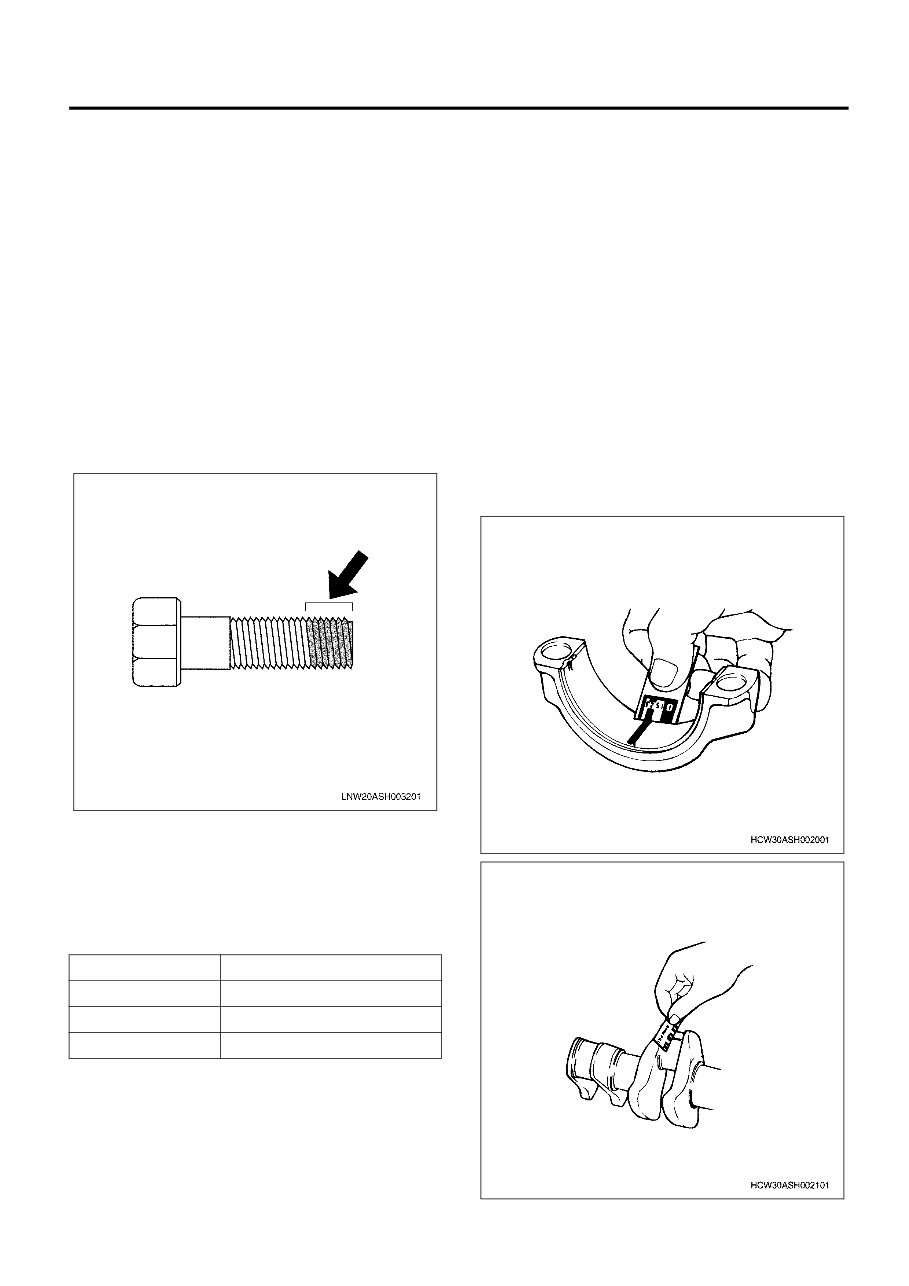
2. Apply Loctite to the top 1/3 of the screw.
3. Tighten the bolt to the specified torque.
Important:
After tightening the bolt, do not apply excessive
torque or try to rotate the bolt until at least one
hour has passed, and the Loctite has hardened.
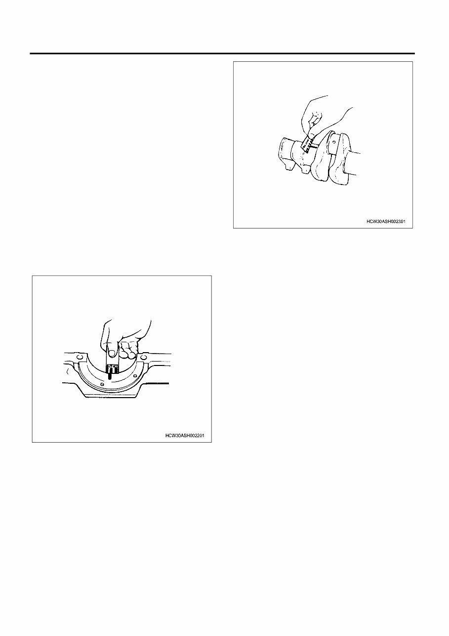
Procedure for using the plastigauge
Example: Procedure for measuring the clearance
between the connecting rod bearing and crank pin.
• Clean the connecting rod and bearing, and install
the bearing to the rod.
• Cut the plastigauge to the same width as the crank
pin, and while avoiding the oil hole of the crank pin
lay the gauge parallel to the pin.
• Line up the marks on the connecting rod and cap,
and install the crank pin. Apply molybdenum disul-
fide to the thread section and seating surface of
the tightening bolt, and rotate both cap and bolt to
the correct torque.
Important:
Do not move the connecting rod while using the
plastigauge.
• Gently remove the cap and connecting rod, and
measure the crushed width of the plastigauge
(clearance between rod and pin) using the scale
printed on the bag.
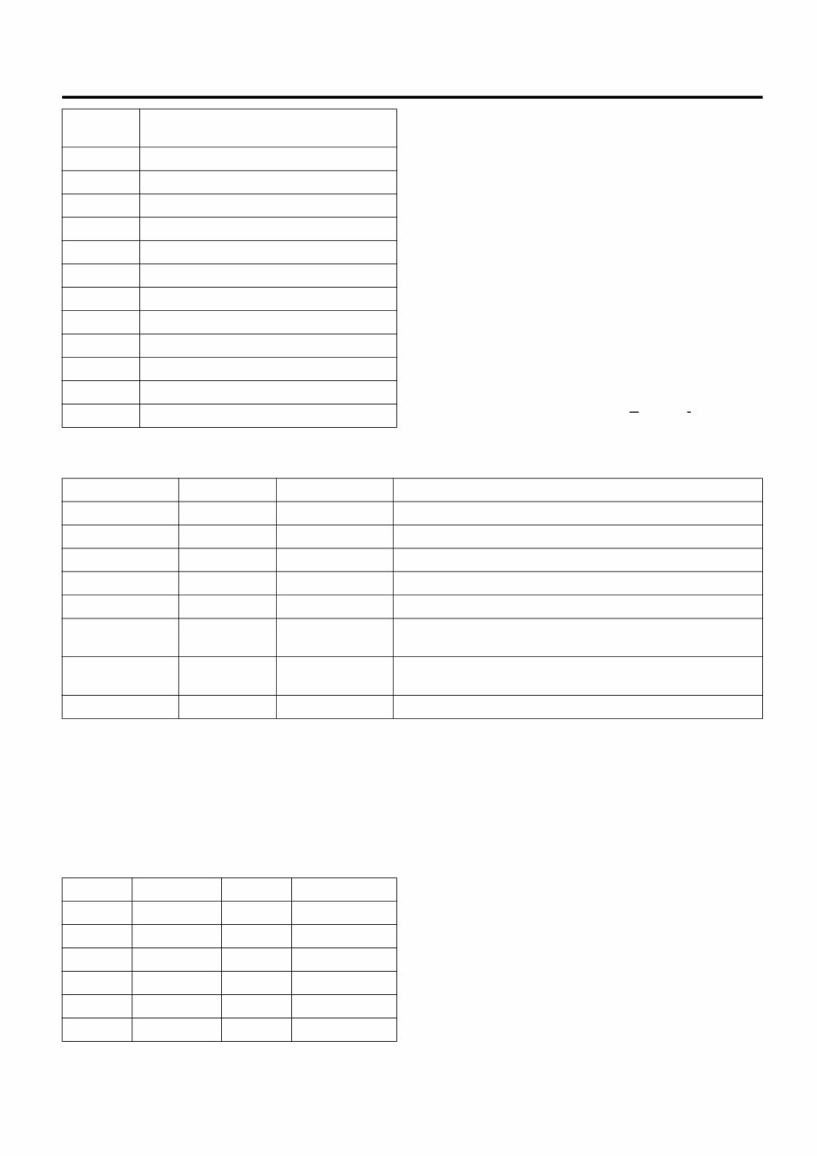
Type Measurable range mm {in}
PG-1 (Green) 0.025 — 0.076 {0.001 — 0.003}
PR-1 (Red) 0.051 — 0.152 {0.002 — 0.006}
PB-1 (Blue) 0.102 — 0.229 {0.004 — 0.009}
0A-6 General Information
Example: Measuring the clearance between the crank
bearing and crank journal
• Clean the clamp face of the cylinder block and
crankcase bearing, and also the bearing, and
install the cylinder block to the crankcase.
• Gently rest the crankshaft on the cylinder block,
and rotate it approximately 30 degree to stabilize it.
• Cut the plastigauge to the same size as the journal
width, and while avoiding the oil hole of the journal
lay the gauge parallel to the journal.
• Gently rest the crankcase on the cylinder block,
apply molybdenum disulfide to the thread section
and seating surface of the tightening bolt, and
tighten in sequence to the correct torque.
Important:
Do not rotate the crankshaft while using the plasti-
gauge.
• Gently remove the crankcase, and measure the
crushed width of the plastigauge (clearance
between bearing and journal) using the scale
printed on the bag.
General Information 0A-7
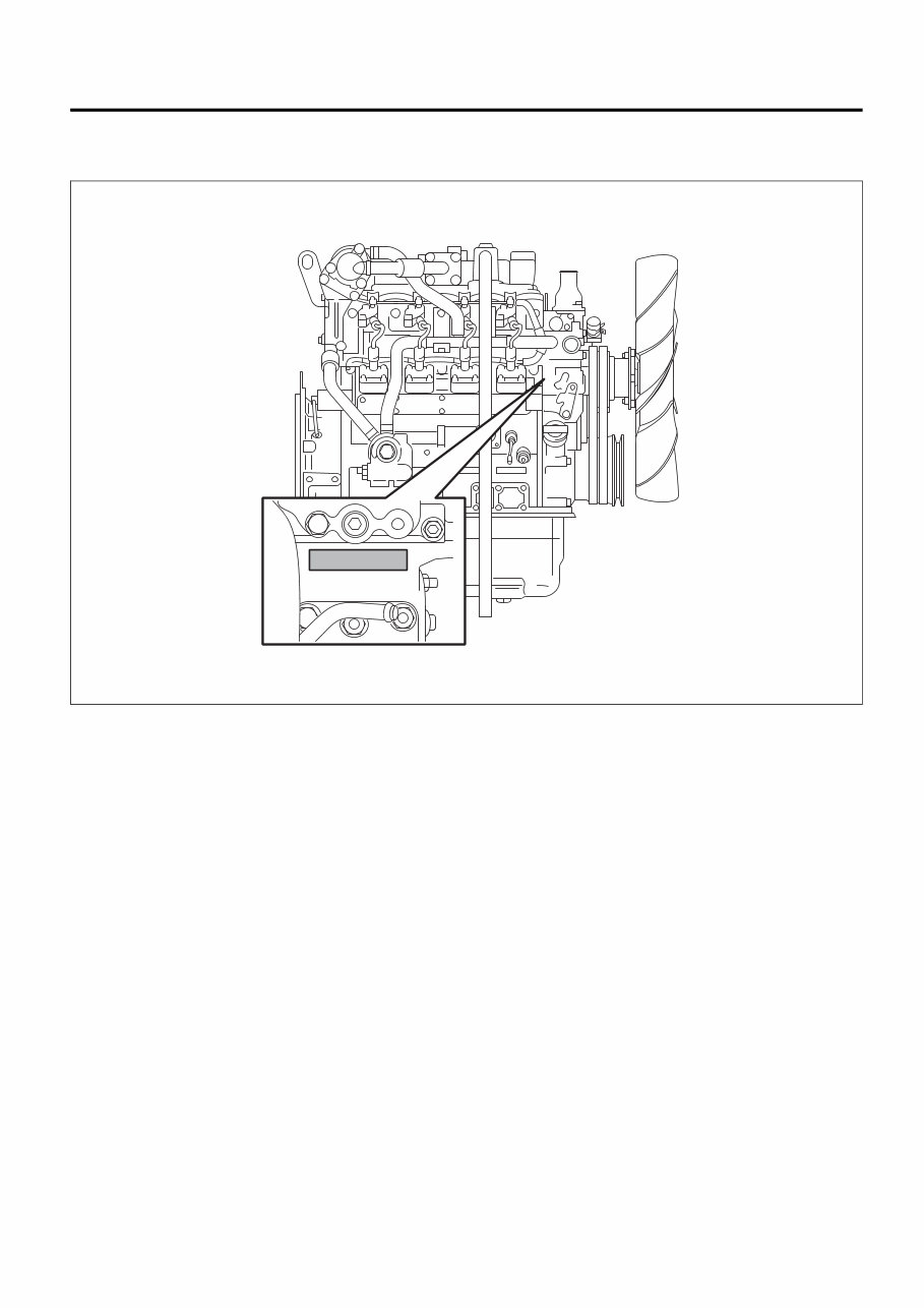
Reading the Model
Engine number stamping position
WSLE0352

0A-8 General Information
General Information
Terminology, description of abbreviations
Terminology definitions
Maintenance standard
The generic name for reference values required for
maintenance, such as nominal dimension, assembly
specification, and limit.
Nominal dimension
Shows the standard value at the point of manufacture
that does not include the common difference.
Assembly specification
Shows the standard value after assembling, repairing,
or adjusting.
Service limit
When this value (dimensions) is reached, it shows that
the part has reached its full limit and must be replaced
or repaired.
Wear
Shows the difference between the dimension of non-
worn part (nominal dimension unless there is such part)
and that of the most worn part (the dimension of worn
part).
Uneven wear
Shows the difference between the maximum and the
minimum wear amount.
Front/Rear, Right/Left, Top/Bottom
These show each orientations of parts installed to the
vehicle when looking from the vehicle's forward direc-
tion.
Unit
Units written to SI conventions (mainly torque, pres-
sure, force)
[Example] Length: mm, Torque: N⋅m {kgf⋅m}
Warning
Items that carry the warning mark pose a danger to life
or threat of serious injury if not strictly observed.
Caution
Items that carry the caution mark may cause injury or
lead to accidents if not strictly observed.
Important
Items that carry the important mark may cause the
vehicle to break down, or may prevent the guaranteed
normal operation of the system or related parts if not
strictly observed.
Note
Items that should receive special mention within a work
procedure.
Description of abbreviations
Abbrevia-
tion
Description
AC Alternating Current
ACC Accessory
ACG Alternating Current Generator
API American Petrol Institute
ASM
(Assy)
Assembly
ATDC After Top Dead Center
BAT, BATT Battery
BRG, Brg Bearing
BKT, BRKT Bracket
BTDC Before Top Dead Center
CO Carbon Oxide
CONN Connector
CPU Central Processing Unit
C/U Control Unit
DC Direct Current
DI Direct Injection
ECU Engine Control Unit/Electronic Control Unit
ECM Engine Control Module
EGR Exhaust Gas Recirculation
Exh, EXH Exhaust
Ft, FRT Front
FWD Forward
F/C Fuel Cut
GND Ground
IC Integrated Circuit
ID Plate Identification Plate
IN Intake, Inlet
ISO International Organization for Standardiza-
tion
I/PUMP Injection Pump
JIS Japanese Industrial Standard
L/H, LH Left Hand
M/V Magnetic Valve
NOx Nitrogen Oxide
N-TDC Number - Top Dead Center
OPT Option
P Pole(S)
PCV Pump Control Valve/Positive Crankcase
Ventilation
General Information 0A-9
SI (International System of Units)
With regards the conversion to SI (International
System of Units)
The introduction of the SI systems aims to internation-
ally unify the metric system and the various units used
by different countries (traditional weights and mea-
sures, the foot pound method etc.), and to curb the
confusion that occurs between the different units (con-
version calculations etc.).
The new calculating method which adopted SI units
was completely adopted in Japan in 1992, and is stan-
dardized by JIS-Z-8203.
All of the units in this manual are written in line
with the International System of Units SI units, and
conventional units are written in { } brackets.
SI
Abbreviation of French word “Le S ysteme I nternational
d’Unites”
Connection between main SI units and conventional units
*1 Published service data may conveniently use kg for
force and mass (weight) instead of kgf.
*2 Some conversion results may be rounded off to 1 or
2 decimal places.
Converting expressions of quantity
When converting, prefixes such as k (kilo) or m (milli)
are used.
• 200 kgf/cm
2
= 19,620 kPa = 19.6 MPa
• 40 mmHg = 5,332 Pa = 5.3 kPa
Conversion formula
Length
• km × 0.6214 = mile
•m × 3.281 = ft
• mm × 0.03937 = in
Pressure
• kPa × 0.0101972 = kg/cm
2
• kPa × 0.145038 = psi
• MPa × 10.197162 = kg/cm
2
• MPa × 145.03774 = psi
Tightening torque
•N⋅m × 0.101972 = kg⋅m
•N⋅m × 0.737562 = lb⋅ft
Speed
• km/h × 0.6214 = MPH
Temperature
• °C × 1.8 + 32 = °F
PM Particulate Matter
PS Pre-Stroke
PTO Power Take Off
QOS Quick On System
Rr, RR Rear
R/H, RH Right Hand
R/L Relay
STD Standard
SW Switch
TICS Timing & Injection rate Control System
VGS Turbo Variable Geometry turbocharger System
W/L Warning Lamp
Abbrevia-
tion
Description
SI Conventional unit Item, unit conversion
Length m m Same as the conventional unit
Weight (Mass) kg kg Same as the conventional unit
Force N * kg, kgf 1 kgf = 9.80665 N
Torque N⋅m * kg⋅m, kgf⋅m 1 kgf⋅m = 9.80665 N⋅m
Pressure Pa * kg/cm
2
, mmHg 1 kgf/cm
2
= 9.80665 kPa, 1 mmHg = 133.3 Pa
Power output,
horsepower
W PS 1 PS = 0.74 kW
Capacity, air vol-
ume displacement
m
3
Liter, L, cc 1 Liter = 1 dm
3
, 1 cc = 1 m Liter = 1 cm
3
Fuel consumption g/(kW⋅h) g/(PS⋅h) 1 g/(PS⋅h) = 1.360 g/(kW⋅h)
M Mega 10
6
1,000,000
k Kilo 10
3
1,000
h Hecto 10
2
100
d Deci 10
-1
0.1
c Centi 10
-2
0.01
m Milli 10
-3
0.001
µ Micro 10
-6
0.000001
You're Reading a Preview
What's Included?
Fast Download Speeds
Online & Offline Access
Access PDF Contents & Bookmarks
Full Search Facility
Print one or all pages of your manual
$31.99
Viewed 23 Times Today


Secure transaction
What's Included?
Fast Download Speeds
Online & Offline Access
Access PDF Contents & Bookmarks
Full Search Facility
Print one or all pages of your manual
$31.99
This is a comprehensive service repair workshop manual for the Isuzu AU-4LE2 BV-4LE2 Diesel Engine. The manual contains easy-to-read text sections with high-quality diagrams and instructions, making it suitable for both do-it-yourself enthusiasts and experienced mechanics. It provides step-by-step instructions and detailed exploded pictures and diagrams to efficiently complete the required job.
The manual covers the following:
- General Information
- Engine Mechanical
- Cooling System
- Fuel System
- Electrical System
- Exhaust System
- Lubrication System
- Intake System
- Preheating System
- And More...
File Format: PDF
Compatibility: All Versions of Windows & Mac
Language: English
Requirements: Adobe Reader & WinZip
All pages are printable, allowing you to save on postage and packaging costs. This manual is a cost-effective way to ensure the proper functioning of your vehicle.


