6A–2 ENGINE MECHANICAL (6VD1 3.2L) Piston and Connecting Rod 6A–76 . . . . . . . . . . . . . . . Piston, Connecting Rod and Associate Parts 6A–76 . . . . . . . . . . . . . . . . . . . . . . . . . . . . . . . . Disassembly 6A–76 . . . . . . . . . . . . . . . . . . . . . . . . . . Inspection and Repair 6A–77 . . . . . . . . . . . . . . . . . . Reassembly 6A–81 . . . . . . . . . . . . . . . . . . . . . . . . . . Cylinder Block 6A–83 . . . . . . . . . . . . . . . . . . . . . . . . . . Cylinder Block and Associated Parts 6A–83 . . . . . Disassembly 6A–83 . . . . . . . . . . . . . . . . . . . . . . . . . . Inspection and Repair 6A–84 . . . . . . . . . . . . . . . . . . Reassembly 6A–85 . . . . . . . . . . . . . . . . . . . . . . . . . . Main Data and Specification 6A–88 . . . . . . . . . . . . . . Special Tool 6A–94 . . . . . . . . . . . . . . . . . . . . . . . . . . . . Service Precaution WARNING: THIS VEHICLE HAS A SUPPLEMENTAL RESTRAINT SYSTEM (SRS). REFER TO THE SRS COMPONENT AND WIRING LOCATION VIEW IN ORDER TO DETERMINE WHETHER YOU ARE PERFORMING SERVICE ON OR NEAR THE SRS COMPONENTS OR THE SRS WIRING. WHEN YOU ARE PERFORMING SERVICE ON OR NEAR THE SRS COMPONENTS OR THE SRS WIRING, REFER TO THE SRS SERVICE INFORMATION. FAILURE TO FOLLOW WARNINGS COULD RESULT IN POSSIBLE AIR BAG DEPLOYMENT, PERSONAL INJURY, OR OTHERWISE UNNEEDED SRS SYSTEM REPAIRS. CAUTION: Always use the correct fastener in the proper location. When you replace a fastener, use ONLY the exact part number for that application. ISUZU will call out those fasteners that require a replacement after removal. ISUZU will also call out the fasteners that require thread lockers or thread sealant. UNLESS OTHERWISE SPECIFIED, do not use supplemental coatings (Paints, greases, or other corrosion inhibitors) on threaded fasteners or fastener joint interfaces. Generally, such coatings adversely affect the fastener torque and the joint clamping force, and may damage the fastener. When you install fasteners, use the correct tightening sequence and specifications. Following these instructions can help you avoid damage to parts and systems.
6A–3 ENGINE MECHANICAL (6VD1 3.2L) General Description Engine Cleanliness And Care An automobile engine is a combination of many machined, honed, polished and lapped surfaces with tolerances that are measured in the thousandths of a millimeter (ten thousandths of an inch). Accordingly, when any internal engine parts are serviced, care and cleanliness are important. Throughout this section, it should be understood that proper cleaning and protection of machined surfaces and friction areas is part of the repair procedure. This is considered standard shop practice even if not specifically stated. D A liberal coating of engine oil should be applied to all friction areas during assembly to protect and lubricate the surfaces on initial operation. D Whenever valve train components, pistons, piston rings, connecting rods, rod bearings, and crankshaft journal bearings are removed for service, they should be retained in order. D At the time of installation, they should be installed in the same locations and with the same mating surfaces as when removed. D Battery cables should be disconnected before any major work is performed on the engine. Failure to disconnect cables may result in damage to wire harness or other electrical parts. D The six cylinders of this engine are identified by numbers; Right side cylinders 1, 3 and 5, Left side cylinders 2, 4 and 6, as counted from crankshaft pulley side to flywheel side. General Information on Engine Service The following information on engine service should be noted carefully, as it is important in preventing damage and contributing to reliable engine performance. D When raising or supporting the engine for any reason, do not use a jack under the oil pan. Due to the small clearance between the oil pan and the oil pump strainer, jacking against the oil pan may cause damage to the oil pick–up unit. D The 12–volt electrical system is capable of damaging circuits. When performing any work where electrical terminals could possibly be grounded, the ground cable of the battery should be disconnected at the battery. D Any time the intake air duct or air cleaner is removed, the intake opening should be covered. This will protect against accidental entrance of foreign material into the cylinder which could cause extensive damage when the engine is started. Cylinder Block The cylinder block is made of aluminum die–cast casting for 75°V–type six cylinders. It has a rear plate integrated structure and employs a deep skirt. The cylinder liner is cast and the liner inner diameter and crankshaft journal diameter are classified into grades. The crankshaft is supported by four bearings of which width is different between No.2, No.3 and No.1, No.4; the width of No.3 bearing on the body side is different in order to support the thrust bearing. The bearing cap is made of nodular cast iron and each bearing cap uses four bolts and two side bolts. Cylinder Head The cylinder head, made of aluminum alloy casting employs a pent–roof type combustion chamber with a spark plug in the center. The intake and exhaust valves are placed in V–type design. The ports are cross–flow type. Valve Train Intake and exhaust camshaft on the both side of banks are driven through an camshaft drive gear by timing belt. The valves are operated by the camshaft and the valve clearance is adjusted to select suitable thickness shim. Intake Manifold The intake manifold system is composed of the aluminum cast common chamber and intake manifold attached with six fuel injectors. Exhaust Manifold The exhaust manifold is made of nodular cast iron. Pistons and Connecting Rods Aluminum pistons are used after selecting the grade that meets the cylinder bore diameter. Each piston has two compression rings and one oil ring. The piston pin made of chromium steel is offset 1mm toward the thrust side, and the thrust pressure of piston to the cylinder wall varies gradually as the piston travels. The connecting rods are made of forged steel. The connecting rod bearings are graded for correct size selection. Crankshaft and Bearings The crankshaft is made of Ductile cast–iron. Pins and journals are graded for correct size selection for their bearing.
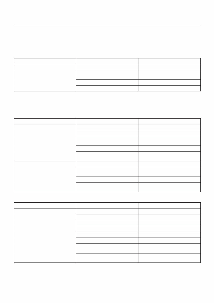
6A–4 ENGINE MECHANICAL (6VD1 3.2L) Engine Diagnosis Hard Starting 1. Starting Motor Does Not Turn Over Troubleshooting Procedure Turn on headlights and starter switch. Condition Possible cause Correction Headlights go out or dim considerably Battery run down or under charged Recharge or replace battery considerably Terminals poorly connected Clean battery posts and terminals and connect properly Starting motor coil circuit shorted Overhaul or replace Starting motor defective Overhaul or replace 2. Ignition Trouble — Starting Motor Turns Over But Engine Does Not Start Spark Test Disconnect an ignition coil from any spark plug. Connect the spark plug tester J–26792 (ST–125), start the engine, and check if a spark is generated in the spark plug tester. Before starting the engine, make sure that the spark plug tester is properly grounded. To avoid electrical shock, do not touch the part where insulation of the ignition coil is broken while the engine is running. Condition Possible cause Correction Spark jumps across gap Spark plug defective Clean, adjust spark gap or replace Ignition timing incorrect Refer to Ignition System Fuel not reaching fuel injector(s) or engine Refer to item 3 (Trouble in fuel system) Valve timing incorrect Adjust Engine lacks compression Refer to item 4 (Engine lacks compression) No sparking takes place Ignition coil disconnected or broken Connect properly or replace Electronic Ignition System with module Replace Poor connections in engine harness Correct Powertrain Control Module cable disconnected or defective Correct or replace 3. Trouble In Fuel System Condition Possible cause Correction Starting motor turns over and spark occurs but engine does not start Fuel tank empty Fill occurs but engine does not start. Water in fuel system Clean Fuel filter clogged Replace filter Fuel pipe clogged Clean or replace Fuel pump defective Replace Fuel pump circuit open Correct or replace Evaporative Emission Control System circuit clogged Correct or replace Multiport Fuel Injection System faulty Refer to “Electronic Fuel Injection” section
6A–5 ENGINE MECHANICAL (6VD1 3.2L) 4. Engine Lacks Compression Condition Possible cause Correction Engine lacks compression Spark plug loosely fitted or spark plug gasket defective Tighten to specified torque or replace gasket Valve timing incorrect Adjust Cylinder head gasket defective Replace gasket Valve incorrectly seated Lap valve Valve stem seized Replace valve and valve guide Valve spring weakened or broken Replace Cylinder or piston rings worn Overhaul engine Piston ring seized Overhaul engine. Engine Compression Test Procedure 1. Start and run the engine until the engine reaches normal operating temperature. 2. Turn the engine off. 3. Remove all the spark plugs. 4. Remove ignition coil fuse (15A) and disable the ignition system. 5. Remove the fuel pump relay from the relay and fuse box. 6. Engage the starter and check that the cranking speed is approximately 300 rpm. 7. Install cylinder compression gauge into spark plug hole. 8. With the throttle valve opened fully, keep the starter engaged until the compression gage needle reaches the maximum level. Note the reading. 9. Repeat the test with each cylinder. If the compression pressure obtained falls below the limit, engine overhaul is necessary. Limit; 1000 kPa (145 psi)
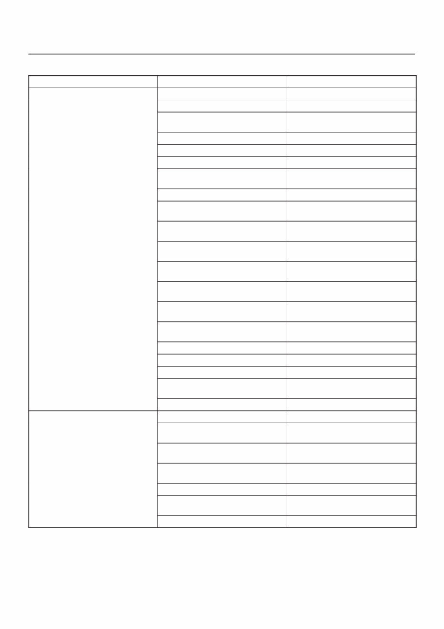
6A–6 ENGINE MECHANICAL (6VD1 3.2L) Rough Engine Idling or Engine Stalling Condition Possible cause Correction Trouble in fuel injection system Idle air control valve defective Replace Throttle shutting off incomplete Correct or replace Throttle position sensor circuit open or shorted Correct or replace Fuel injector circuits open or shorted Correct or replace Fuel injectors damaged Replace Fuel pump relay defective Replace Mass Airflow Sensor circuit open or poor connections Correct or replace Mass Airflow Sensor defective Replace Manifold Absolute Pressure Sensor circuit open or poor connections Correct or replace Manifold Absolute Pressure Sensor defective Replace Engine Coolant Temperature Sensor circuit open or poor connections Correct or replace Engine Coolant Temperature Sensor defective Replace Intake Air Temperature sensor circuit open or poor connections Correct or replace Intake Air Temperature sensor defective Replace Knock Sensor (KS) cable broken or poor connections Correct or replace KS defective Replace KS Module circuits open or ground Correct or replace KS Module defective Replace Vehicle Speed Sensor circuit open or shorted Correct or replace Vehicle Speed Sensor defective Replace Trouble in emission control system Powertrain Control Module defective Replace Exhaust Gas Recirculation Valve circuit open or poor connections Correct or replace Exhaust Gas Recirculation Valve faulty Replace Canister purge valve circuit open or poor connections Correct or replace Canister purge valve defective Replace Evaporative Emission Canister Purge control valve defective Replace Trouble in ignition system Refer to “Hard Start”
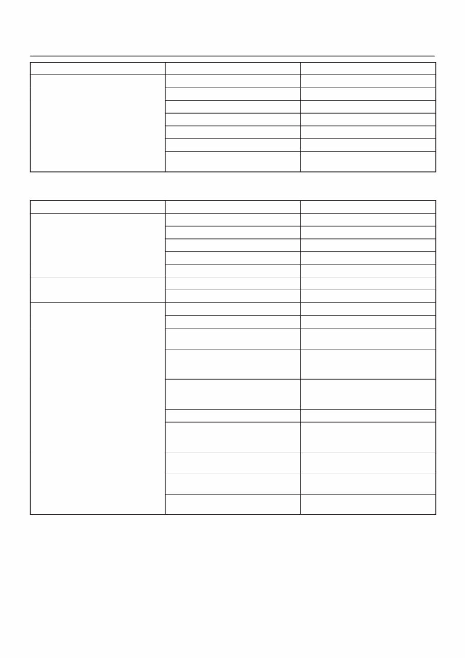
6A–7 ENGINE MECHANICAL (6VD1 3.2L) Condition Correction Possible cause Others Engine lacks compression Refer to “Hard Start” Valve incorrectly seated Lap valve Air Cleaner Filter clogged Replace filter element Valve timing incorrect Readjust Idle air control valve broken Replace Fast idle solenoid defective Replace Positive Crankcase Ventilation valve defective or clogged Replace Rough Engine Running Condition Possible cause Correction Engine misfires periodically Ignition coil layer shorted Replace Spark plugs fouling Clean or install hotter type plug Spark plug(s) insulator nose leaking Replace Fuel injector(s) defective Replace Powertrain control module faulty Replace Engine knocks periodically Spark plugs running too hot Install colder type spark plugs Powertrain control module faulty Replace Engine lacks power Spark plugs fouled Clean Fuel injectors defective Replace Mass Airflow Sensor or Intake Airflow Sensor circuit defective Correct or replace Manifold Absolute Pressure (MAP) Sensor or Manifold Absolute Pressure Sensor circuit defective Correct or replace Engine Coolant Temperature Sensor or Engine Coolant Temperature Sensor circuit defective Correct or replace Powertrain Control Module faulty Replace Intake Air Temperature Sensor or Intake Air Temperature Sensor circuit defective Correct or replace Throttle Position Sensor or Throttle Position Sensor circuit defective Correct or replace Knock Sensor or Knock Sensor circuits defective Correct or replace Knock Sensor Module or Knock Sensor Module circuits defective Correct or replace
6A–8 ENGINE MECHANICAL (6VD1 3.2L) Hesitation Condition Possible cause Correction Hesitation on acceleration Throttle Position Sensor adjustment incorrect Replace throttle valve assembly Throttle Position Sensor circuit open or shorted Correct or replace Excessive play in accelerator linkage Adjust or replace Mass Airflow Sensor circuit open or poor connections Correct or replace Mass Airflow Sensor defective Replace Manifold Absolute Pressure (MAP) Sensor circuit open or shorted Correct or replace MAP Sensor defective Replace Intake Air Temperature (IAT) Sensor circuit open or poor connections Correct or replace Knock Sensor (KS) circuit open or poor connections Correct or replace KS defective Replace KS Module circuits open or shorted Correct or replace KS Module defective Replace IAT Sensor defective Replace Hesitation at high speeds Fuel tank strainer clogged Clean or replace (Fuel pressure too low) Fuel pipe clogged Clean or replace Fuel filter clogged Replace Defective fuel pump system Check and replace Fuel Pressure Control Valve leaking Replace Hesitation at high speeds (Fuel injector not working normally) Power supply or ground circuit for Multiport Fuel Injection System shorted or open Check and correct or replace Fuel Injector defective Replace Cable of Multiport Fuel Injection System circuit open or poor connections Correct or replace
6A–9 ENGINE MECHANICAL (6VD1 3.2L) Condition Correction Possible cause Hesitation at high speeds Powertrain Control Module defective Replace Throttle Position Sensor cable broken or poor connections Correct or replace Throttle Position Sensor defective Replace Engine Coolant Temperature Sensor circuit open or shorted Correct or replace Engine Coolant Temperature Sensor defective Replace Mass Airflow Sensor circuit open or poor connections Correct or replace Mass Airflow Sensor defective Replace MAP Sensor cable broken or poor connections Correct or replace MAP Sensor defective Replace IAT Sensor circuit open or poor connections Correct or replace IAT Sensor defective Replace KS circuit open or poor connections Correct or replace KS defective Replace KS Module circuit open or shorted Correct or replace KS Module defective Replace Throttle valve not fully opened Check and correct or replace Air Cleaner Filter clogged Replace filter element Power supply voltage too low Check and correct or replace
6A–10 ENGINE MECHANICAL (6VD1 3.2L) Engine Lacks Power Condition Possible cause Correction Trouble in fuel system Fuel Pressure Control Valve not working normally Replace Fuel injector clogged Clean or replace Fuel pipe clogged Clean Fuel filter clogged or fouled Replace Fuel pump drive circuit not working normally Correct or replace Fuel tank not sufficiently breathing due to clogged Evaporative Emission Control System circuit Clean or replace Water in fuel system Clean Inferior quality fuel in fuel system Use fuel of specified octane rating Powertrain Control Module supplied poor voltage Correct circuit Throttle Position Sensor cable broken or poor connections Correct or replace Throttle Position Sensor defective Replace Mass Airflow Sensor not working normally Replace Manifold Absolute Pressure Sensor not working normally Replace Intake Air Temperature Sensor not working normally Replace Engine Coolant Temperature Sensor circuit open or shorted Correct or replace Engine Coolant Temperature Sensor defective Replace Powertrain Control Module defective Replace Trouble in intake or exhaust system Air Cleaner Filter clogged Replace filter element Air duct kinked or flattened Correct or replace Ignition failure ———— Refer to Hard Start Troubleshooting Guide Heat range of spark plug inadequate Install spark plugs of adequate heat range Ignition coil defective Replace
This workshop manual provides comprehensive coverage of the service and repair procedures for the Isuzu Engine Mechanical 6VD1 3.2L. Whether you are a first-time owner, amateur, or professional technician, this manual is designed to be easy to read and contains all the necessary information to perform procedures correctly. By keeping this manual handy and performing routine preventive maintenance, you can save time and money by preventing premature failure and unnecessary repairs.
Manual Contents:
Engine Mechanical 6A1
Engine Cooling 6B1
Engine Fuel 6C1
Engine Electrical 6D11
Ignition System 6D21
Starting and Charging System 6D31
Driveability and Emissions 6E1
Engine Exhaust 6F1
Engine Lubrication 6G1
Engine Speed Control System 6H1
Induction 6J1
ENGINE MECHANICAL (6VD1 32L)
Service Precaution 6A2
General Description 6A3
Engine Diagnosis 6A4
Cylinder Head Cover LH 6A17
Removal 6A17
Installation 6A18
This service repair manual is available instantly, saving you money on postage and packaging. It is a valuable resource that can save you a lot of time and provide in-depth knowledge about your Isuzu Engine Mechanical 6VD1 3.2L. All pages are printable, making it even more convenient.
File Format: PDF
Compatibility: All Versions of Windows & Mac
Language: English
Requirements: Adobe Reader
Don't wait any longer! Get your hands on this comprehensive manual now and take control of your maintenance and repair needs.
Recently Viewed
5,521,897Happy Clients
2,594,462eManuals
1,120,453Trusted Sellers
15Years in Business
Price:
Actual Price:
Isuzu Engine Mechanical 6VD1 3.2L Workshop Service Repair Manual