

Isuzu 6UZ1X Engine OEM Service & Repair Manual
What's Included?
Fast Download Speeds
Online & Offline Access
Access PDF Contents & Bookmarks
Full Search Facility
Print one or all pages of your manual

CNH
Copyright © 2006 CNH France S.A.
Printed in France
November 2006 Lep 87606798A
SERVICE MANUAL
6UZ1X
ISUZU ENGINE
NOT FOR PRINT

Lep 87606798A Issued 11/06
NOT FOR PRINT

General Information OA-1
General Information
General Information
Contents
General Information . . . . . . . . . . . . . . . . . . . . . . . 0A-2
Service Precautions . . . . . . . . . . . . . . . . . . . . . . 0A-2
Reading the Model . . . . . . . . . . . . . . . . . . . . . . . 0A-6
General Information . . . . . . . . . . . . . . . . . . . . . . 0A-6
NOT FOR PRINT
General Information OA-2
General Information
Service Precautions
In order to work safely
1. Use an engine stand when lowering the engine
from the machine.
Do not put the engine on the ground directly. And
put it so that the oil pan is not affected.
2. When performing by two persons or more, confirm
safety each other.
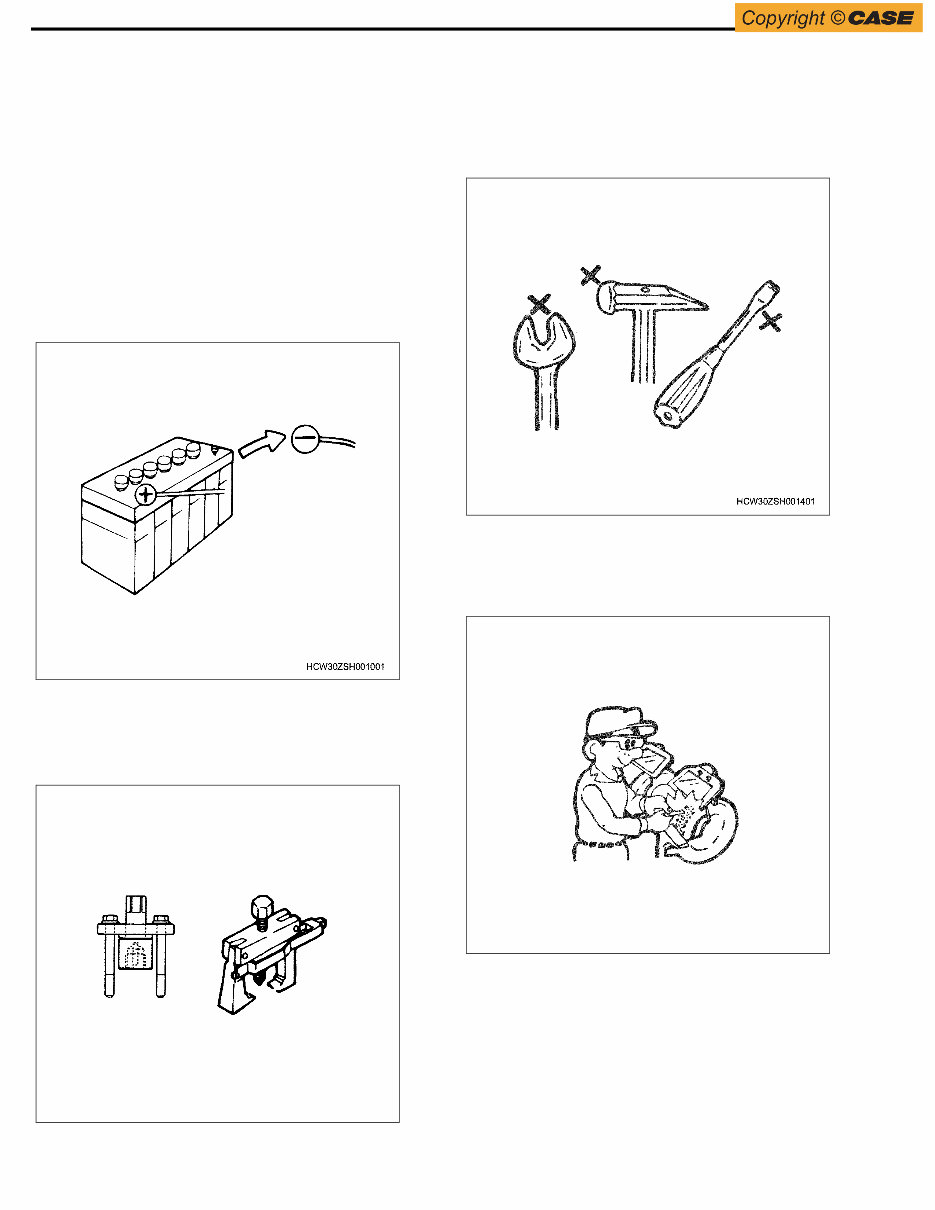
3. If performing repair on the electrical system, always
disconnect the negative cable from the battery
terminal beforehand. Before removing the battery
cover, keep fire away.
4. In badly ventilated indoor workshop, do not run the
engine for a long time or perform painting work.
5. Be sure to use special tools as instructed. Use of
other than the specified tool may cause damage of
parts or injury.
6. Maintain tools, measuring equipment and special
tools in good condition, and prepare them before
use. Do not use worn wrenches, hammers that has
the rounded striking surface of the head or chipped
chisels, etc.
7. When using devices such as a grinder, crane and
welder, follow the instructions and use a special
care.
Also, when performing other works, protect
yourself with clothes and other safety tools.
WSHK0190
WSHK0191
NOT FOR PRINT
General Information OA-3
8. After servicing the fuel system, always check for
fuel leakage. (This may cause a fire.)
9. When handling highly-volatile material, take
extreme care not to let it catch fire.
Be sure to wipe off spilled oil and grease on
rubbers, as this may cause the rubber to
deteriorate.
Replacement parts and part numbers
1. Always replace the packing, oil seal, O-ring,
caulking lock nut, folding type lock plate, split pin,
etc. with new ones every time they are
disassembled.
2. The part number information in this manual may
not represent availability of supply, or the numbers
may have been changed due to revision. Always
check the numbers with the part catalog before
use.
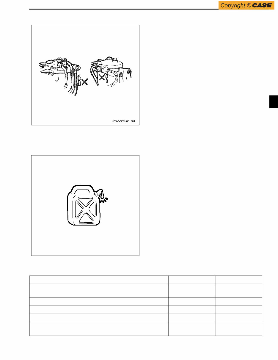
Liquid gasket
1. Remove old liquid gasket completely from liquid
gasket applied area on each part using a scraper
during disassembly. Wipe off oil, water, dust, etc.
with cloth and apply specified liquid gasket on each
area before assembly.
2. If the gasket remover (ThreeBond, Pando 391D) is
used to clean easily, it is recommended that you
wait for about 10 minutes after application, and
then remove it.
However, do not use it for resin or painted parts.
3. Be careful to apply appropriate amount, not
excessively or insufficiently.
Always, the start and end of the application should
be overlapped.
4. Take care not to misalign the applied part and
opposite one when assembling it after application.
If the parts are misaligned, apply the liquid gasket
again. Especially for the oil pan, use the same size
of studs as a guide since it has no positioning such
as a knock pin.
5. Apply liquid gasket and assemble it within 7
minutes.
If more than 7 minutes have elapsed, remove the
existing liquid gasket and apply again.
6. Start the engine more than 30 minutes after each
part is assembled.
Liquid gasket
WSHK0192
Sealed Location Product Name Manufacturer
Upper surface of the mating portion between cylinder block –
flywheel housing
1207B ThreeBond
Between front cover – cylinder block 1201 ThreeBond
Between cylinder block – flywheel housing – crank case 1201 ThreeBond
Between cylinder block – crank case FMD –127 Loctite
Lower surface of the mating portion between crankcase – flywheel
housing
1207B ThreeBond
NOT FOR PRINT
General Information OA-4
• Be sure to use liquid gasket of product name
described above or equivalent product.
• Use the appropriate amount of liquid gasket.
Follow the instructions of products.
Method of application
1. Wipe off water, oil or grease from contact surface.
The contact surface should be dry.
2. Apply liquid gasket of specified bead width on the
one side of contact surfaces. At this time, there
should be no gap in bead.
Note:
If the method of application is described in service
manual, follow the description.
Work procedure
1. Wipe off oil, grease and water completely from the
contact surface of bolt, bolt hole and threads
portion of nut. The contact surface should be dry.
2. Apply Loctite on 1/3 of the tip of threads.
3. Tighten the bolt to the specified torque.
Important:
After tightening, do not give excessive torque or
vibration for at least 1 hour until Loctite hardens.
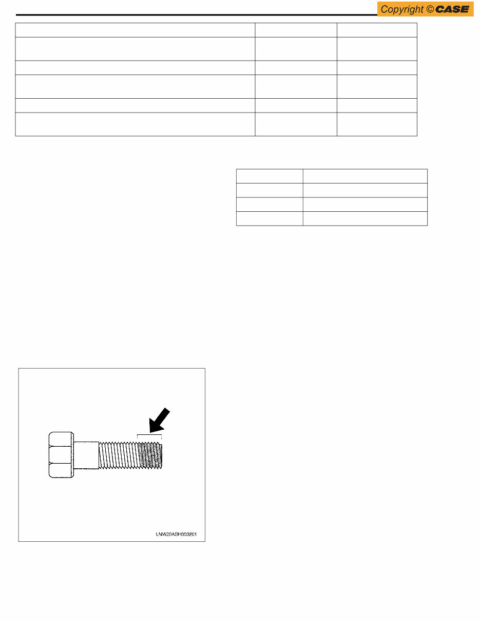
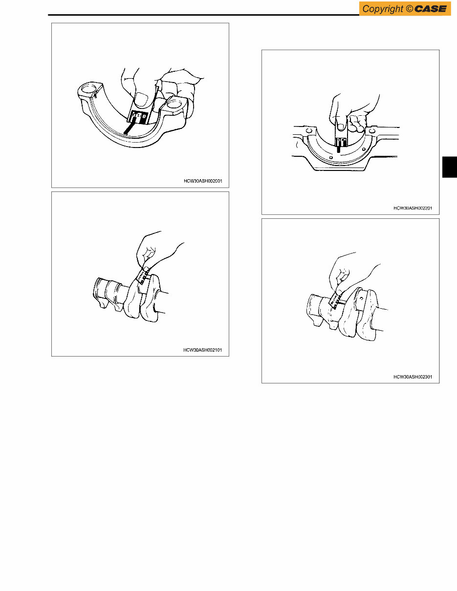
How to use Plastigauge
(Example) Measurement of clearance between
connecting rod bearing and crank pin
• Clean the connecting rod and the bearing, and
assemble the bearing to the connecting rod.
• Cut the Plastigauge in the width of the crank pin,
and place it parallel, away from the oil hole of the
pin.
• Align the stamp mark of connecting rod with that of
cap, and assemble them to the crank pin. Apply
molybdenum disulphide to the threads and the
seating surface of the tightening bolts, and tighten
the bolts on the cap alternately to the specified
torque.
Important:
Never move the connecting rod while using the
Plastigauge.
• Carefully remove the cap and the connecting rod,
and measure the width (clearance) of flattened
Plastigauge using the scale printed on the bag.
Lower surface of the mating portion between crankcase – front
cover
1207B Three Bond
Contact part of cylinder head that nozzle sleeve is pushed to TL290 Loctite
Sealing cup push part between cylinder block – head 962T
123T
Loctite
Hermetic seal
Plug nipple of oil cooler #575 Loctite
O-ring omission prevention agent 1208
CH Dyne #290
Three Bond
Cement dyne
Sealed Location Product Name Manufacturer
Type Measurable Range (mm)
PG-1 (Green) 0.025 — 0.076
PR-1 (Red) 0.051 — 0.152
PB-1 (Blue) 0.102 — 0.229
NOT FOR PRINT
General Information OA-5
(Example) Measurement of clearance between
crankshaft bearing and crankshaft journal.
• Clean the bearing installation surfaces on the
crankcase and on the cylinder block, and the
bearings. Then assemble each bearing to the
cylinder block and the crankcase.
• Put the crankshaft on the cylinder block carefully,
and rotate the crankshaft for approx. 30 degrees to
fit in.
• Cut the Plastigauge in the width of the crankshaft
journal, and place it parallel, away from the oil hole
of the journal.
• Put the crankcase on the cylinder block carefully,
and apply molybdenum disulphide to the threads
and the seating surface of the tightening bolts.
Then tighten them to the specified torque in the
specified order.
Important:
Never rotate the crankshaft while using the Plastigauge.
• Carefully remove the crankcase, and measure the
width (clearance) of the flattened Plastigauge using
the scale printed on the bag.
NOT FOR PRINT
General Information OA-6
Reading the Model
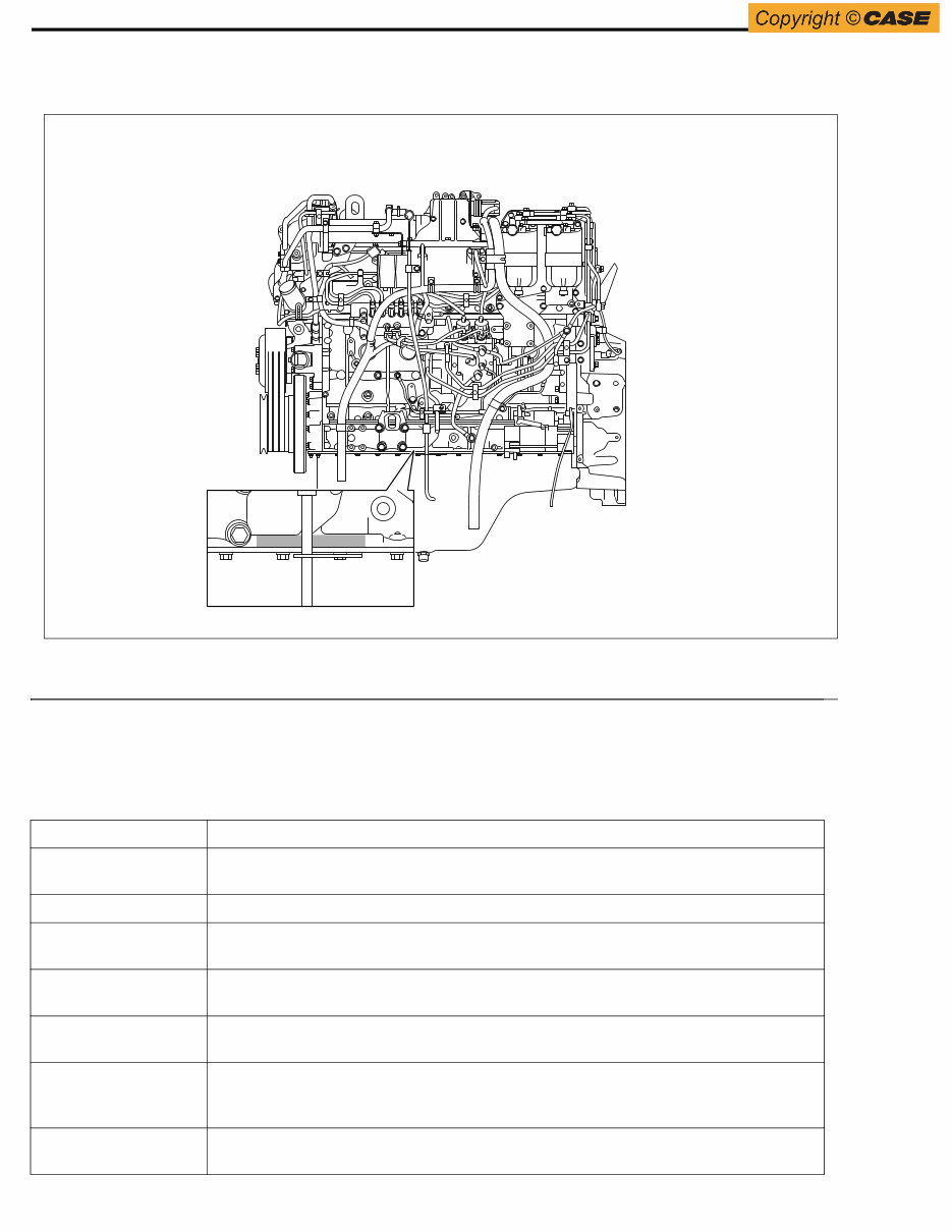
Stamping position of engine number
Name
1. Engine Number Stamp (6UZ)1-······)
General Information
Description of terms and abbreviations
Definition of terms
WSUZ0142
Term Description
Specifications General term for the specified values that are necessary for service work, such as
nominal dimension, assembly specifications and service limit.
Nominal dimension It indicates the value without tolerance at the time of manufacture.
Assembly
specifications
It indicates the specified value after assembly, repair or adjustment.
Service limit It indicates the limit value that the part must be repaired or replaced when it reaches this
value (dimension).
Front/Rear, Right/Left,
Top/Bottom
These indicate directions same as those of the vehicle when mounted on.
Units In addition to SI unit, conventional unit is also shown (toque, pressure, force, in
particular).
[Example] Length: mm, Torque: N⋅m {kgf⋅m}
Warning It means the items that danger of personal life or serious injury may occur if you do not
follow.
NOT FOR PRINT
General Information OA-7
Abbreviation
SI (International System of Unit)
About changeover to SI (International System of
Unit)
This was introduced with the aim to internationally unify
the metric system and the units (Shakkanho (Japanese
measuring system), Foot-pound system, etc.) which are
used conventionally in various countries, and to control
the confusion among each unit (conversion by
calculation etc.)
Caution It means the items that injury or accident may occur if you do not follow.
Important It means the items that related parts and system may lose the normal performance, or a
fault may occur in vehicle.
Note It means the items which is noted in procedures.
Term Description
Abbreviation Description
AC Alternating Current
ACC Accessory
ACG Alternating Current Generator
API American Petrol Institute
ASM (Assy) Assembly
ATDC After Top Dead Center
BAT, BATT Battery
BRG, Brg Bearing
BKT, BRKT Bracket
BTDC Before Top Dead Center
CO Carbon Oxide
CONN Connector
CPU Central Processing Unit
C/U Control Unit
DC Direct Current
DI Direct Injection
ECU Engine Control Unit/Electronic
Control Unit
ECM Engine Control Module
EGR Exhaust Gas Recirculation
Exh, EXH Exhaust
Ft, FRT Front
FWD Forward
F/C Fuel Cut
GND Ground
IC Integrated Circuit
ID plate Identification Plate
IN Intake, Inlet
ISO International Organization for
Standardization
I/PUMP Injection Pump
JIS Japanese Industrial Standards
L/H, LH Left Hand
M/V Magnetic Valve
NOx Nitrogen Oxide
N-TDC Number - Top Dead Center
OPT Option
P Pole(S)
PCV Pump Control Valve/Positive
Crankcase Ventilation
PM Particulate Matter
PS Pre-Stroke
PTO Power Take Off
QOS Quick On System
Rr, RR Rear
R/H, RH Right Hand
R/L Relay
STD Standard
SW Switch
TICS Timing & Injection rate Control
System
A type of injection system
VGS Turbo Variable Geometry turbocharger
System
Variable turbo, VGS turbo
W/L Warning Lamp
Abbreviation Description
NOT FOR PRINT
General Information OA-8
In Japan, the new calculation method that fully adopts
SI unit was issued in 1992 and standardized in JIS-Z-
8203.
In this manual, SI units which are international unit
system are described, and conventional units are
also described in { }.
SI
Abbreviation of French word “Le S ysteme I nternational
d’Unites”
Relationship between SI and conventional units
*1 Some service data which have been issued already
use “kg” instead of “kgf” to represent force and weight
(mass) for convenience sake.
*2 The results of the conversion may be rounded to one
or two decimal places.
Conversion of numeric representation
Prefixes such as “k (kiro)” or “m (milli)” are used
for numeric conversion.
• 200 kgf/cm
2
= 19,620 kPa = 19.6 MPa
• 40 mmHg = 5,332 Pa = 5.3 kPa
Table of Isuzu standard tightening torque
The tightening torque values in the following table are
applied to the places where tightening torque is not
specified.
SI Conventional Unit Item, Unit Conversion
Length m m Same as conventional one
Weight (mass) kg kg Same as conventional one
Force N * kg, kgf 1 kgf = 9.80665 N
Torque N⋅m * kg⋅m, kgf⋅m 1 kgf⋅m = 9.80665 N⋅m
Pressure Pa * kg/cm
2
, mmHg 1 kgf/cm
2
= 9.80665 kPa, 1 mmHg = 133.3 Pa
Power output,
horsepower
W PS 1 PS = 0.74 kW
Cubic volume,
displacement
m
3
Liter, L, cc 1 Liter = 1 dm
3
, 1 cc = 1 mLiter = 1 cm
3
Fuel
consumption
g/(kW⋅h) g/(PS⋅h) 1 g/(PS⋅h) = 1.360 g/(kW⋅h)
M Mega 10
6
1,000,000
k Kiro 10
3
1,000
h Hecto 10
2
100
d Deci 10
-1
0.1
c Centi 10
-2
0.01
m Milli 10
-3
0.001
μ Micro 10
-6
0.000001
NOT FOR PRINT
You're Reading a Preview
What's Included?
Fast Download Speeds
Online & Offline Access
Access PDF Contents & Bookmarks
Full Search Facility
Print one or all pages of your manual
$71.99
Viewed 97 Times Today


Secure transaction
What's Included?
Fast Download Speeds
Online & Offline Access
Access PDF Contents & Bookmarks
Full Search Facility
Print one or all pages of your manual
$71.99
- This professional technical manual provides service, maintenance, troubleshooting, and replacement procedures for the Isuzu 6UZ1X engine.
- The manual includes step-by-step instructions, clear images, and exploded-view illustrations, making it useful for both professional mechanics and DIY enthusiasts.
- It is not a generic repair manual but the manufacturer-sourced OEM repair manual used by professional technicians.
- It contains every troubleshooting and replacement procedure provided by the manufacturer, eliminating the need to flip through numerous pages to find specific information.
- The manual is easily accessible and can be carried around, searched, bookmarked, and printed for convenience.
- Printable: Yes
- Language: English
- Compatibility: Compatible with various electronic devices, including PC & Mac computers, Android and Apple smartphones & tablets, etc.
- Requirements: Adobe Reader (free)


