WORKSHOP MANUAL 4HK1-6HK1 ISUZU ENGINE Workshop manual integration of the following models: E385 (Tier 3) All information, illustrations and specifications in this manual are based on the latest product information available at the time of publication. The right is reserved to make changes at any time without notice. NEW HOLLAND KOBELCO CONSTRUCTION MACHINERY S.p.A. - PRODUCT SUPPORT FORM No. 604.13.649 - Edition - January 2006 R3807 R3807
Introduction IN-1 TO THE READER • This manual was written for a skilled technician and contains all the technical information needed to repair this engine. • Read this manual carefully for the information concerning repairing operations. • For any question or comment, or should you notice any mistake concerning the contents of this manual, please contact: NEW HOLLAND KOBELCO CONSTRUCTION MACHINERY S.p.A. Strada Settimo, 323 San Mauro Torinese (TO) 10099 ITALY PRODUCT SUPPORT Fax. ++39 011 6877357 FURTHER REFERENCES PAGE NUMBER • Every page carries a number on the top right corner. Every page contains the following information: Example: 1A - 1 Progressive page number for each section Section number
IN-2 Introduction UNITS OF MEASURE This manual adopts the units of measure based on International System. The MKSA system units of measure are indicated within brackets after the units of measure of the International System. Example: 24.5 MPa (250 kgf/cm 2 ) The following table converts the International System units of measure in some of the main units belonging to other system. Quantity To convert from (IS) Into (Others) Multiply by Quantity To convert from (IS) Into (Others) Multiply by Lenght mm in 0.03937 Pressure MPa kgf/cm 2 10.197 mm ft 0.003281 MPa psi 145.0 Volume L US gal 0.2642 Power kW CV-PS 1.360 L US qt 1.057 kW HP 1.341 m 3 yd 3 1.308 Temperature °C °F °C x 1.8 + 32 Mass kg lb 2.205 Speed km/h mph 0.6214 Force N kgf 0.10197 min -1 rpm 1.0 N lbf 0.2248 Capacity L/min US gpm 0.2642 Torque N.m kgf.m 0.10197 mL/rev cc/rev 1.0 N.m lbf.ft 0.7375
General Information 0A-1 GENERAL INFORMATION General Information Contents General Information . . . . . . . . . . . . . . . . . . . . . . . 0A-2 Service Precautions . . . . . . . . . . . . . . . . . . . . . . 0A-2 Reading the model . . . . . . . . . . . . . . . . . . . . . . . 0A-6 General information . . . . . . . . . . . . . . . . . . . . . . 0A-7
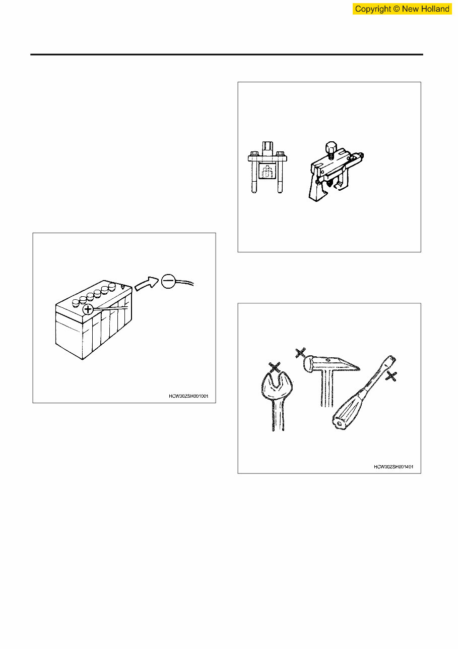
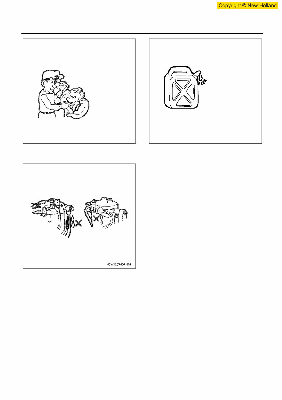
0A-2 General Information General Information Service Precautions In order to carry out work safely 1. Always use an engine stand when taking the engine down from the vehicle. Do not place the engine directly onto the ground, or place in a manner that interferes with the oil pan. 2. If you are working together with others, always pay attention to each other's safety. 3. If you are repairing any part of the electrical system, always remove the minus side cable from the battery terminal before starting work. If you are removing the battery cover, always remove the cover in a place that is away from sources of fire/ heat. 4. Do not perform painting work or leave the engine running for long periods of time in an enclosed or badly ventilated indoor workshop. 5. Always use the correct specialized tool indicated in the instructions. Using the incorrect tool may cause damage to the parts or injury to the person using the tool. 6. All regular tools, gauges and special tools should be regularly inspected, and prepared before starting work. Do not use bent spanners, hammers with damaged edges, chipped chisels, or any other faulty or damaged tools. 7. Always pay close attention to safety and handling requirements when using grinders, cranes, welders, and other such equipment. Moreover, always wear the correct protective garments and use the necessary safety tools for the job in hand.
General Information 0A-3 8. Always check that there are no fuel leaks when performing maintenance work on the fuel system. (It may cause a fire.) 9. Pay close attention to the risk of ignition if you are handling parts that carry a high voltage. Furthermore, any oil or fat spilt onto rubber parts must be wiped off immediately, as it will cause deterioration of the rubber. Replacement parts and part numbers. 1. Always replace packing, oil seals, o-rings, caulking lock nuts, folding lock plates, split pins and other such parts with brand new parts. 2. The parts numbers contained in this manual may not represent the supply condition of the parts, and the part numbers may be changed due to revisions. Therefore, parts should always be checked against a parts catalogue before use. Liquid gasket 1. Each time you disassemble parts that use liquid gasket, completely remove the old gasket residue from each of the parts and matching sections using a scraper, then clean each of the parts to completely remove oil, water, and dirt etc. from the various surfaces. Using the specified type of liquid gasket, apply new liquid gasket to each of the surfaces before reassembling the parts. 2. In order to make it easier to clean liquid gasket surfaces, apply gasket remover liquid (Pando- 391D made by Three Bond Co., Ltd.) and leave the part to stand for approximately 10 minutes, after which the old liquid gasket residue will be easier to remove. However, this should not be used on resin components or painted components. 3. Please take care not to apply too much or too little liquid gasket. Also, you should always re-apply the liquid gasket upon itself when you start and finish application. 4. Make sure that there are no gaps when re- installing the liquid gasket parts to each other. If there are gaps between the two parts, re-apply the liquid gasket. Some parts, especially the oil pan, use the same size studs as a guide to eliminate the need for knock pin positioning etc. 5. Re-install these parts within 7 minutes of applying the liquid gasket.
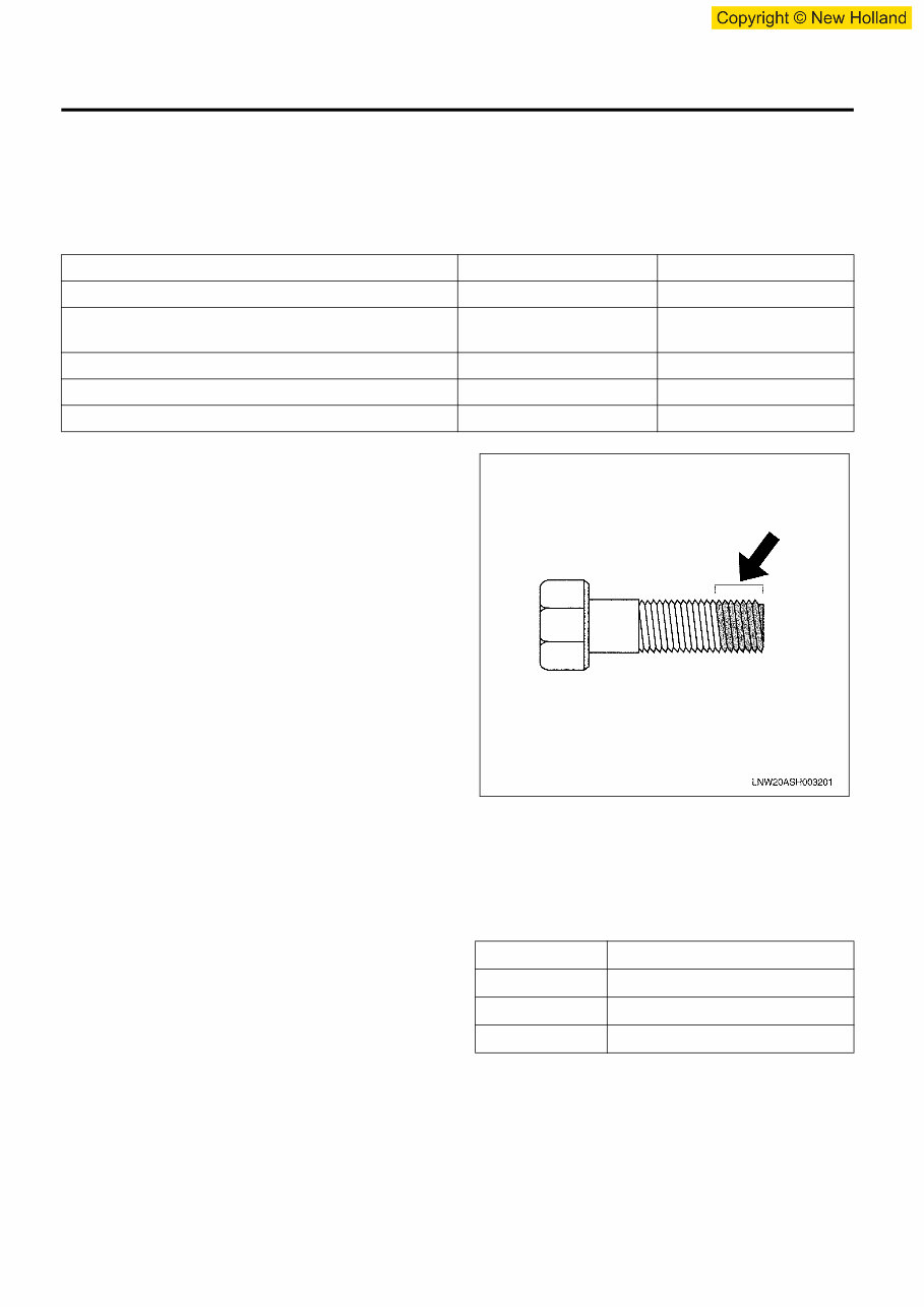
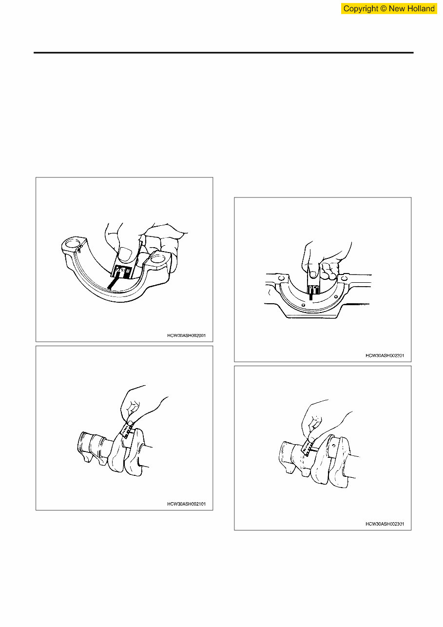
0A-4 General Information If more than 7 minutes passes, remove the previous liquid gasket and re-apply it. 6. Please wait for at least 30 minutes since the last part is installed before starting the engine. Liquid gasket • Always use the liquid gasket products listed above, or a liquid gasket identical to the ones listed above. • Use the correct quantity of liquid gasket. Always follow the handling instructions for each product. Application procedure 1. Wipe the contact surfaces clean of all water, fat or oil. The contact surfaces should be dry. 2. Apply a regular bead width of liquid gasket to one of the contact surfaces. Make sure that the bead does not break at this point. Notes: If there are special regulations concerning the application procedure in the repair document, please follow those regulations. Work procedure 1. Wipe the joint surfaces of the bolt, bolt hole, and screw thread section clean of water, fat, and oil. The contact surfaces should be dry. 2. Apply Loctite to the top 1/3 of the screw. 3. Tighten the bolt to the correct tightening torque. Important: After tightening the bolt, do not apply excessive torque or try to rotate the bolt until at least one hour has passed, and the Loctite has hardened. Procedure for using the Plastiguage Example: Procedure for measuring the clearance between the connecting rod bearing and crank pin. • Clean the connecting rod and bearing, and install the bearing to the rod. • Cut the plastiguage to the same width as the crank pin, and while avoiding the oil pore of the crank pin lay the gauge parallel to the pin. Seal section Product name Manufacturer's name Between cylinder block and – Flywheel housing 1207B Three Bond Between cylinder block and – Flywheel housing and – Crankcase 1207B Three Bond Between cylinder block and – Crank case 1207B Three Bond Between cylinder block and – Front cover 1207B Three Bond Cylinder block, head plug nipple, unit, switches 262 Loctite Type Measurable range mm (in) PG-1 (Green) 0.025 – 0.076 (0.001 – 0.003) PR-1 (Red) 0.051 – 0.152 (0.002 – 0.006) PB-1 (Blue) 0.102 – 0.229 (0.004 – 0.009)
General Information 0A-5 • Line up the marks on the connecting rod and cap and install the crank pin, apply molybdenum disulphide to the thread section and bearing surface of the fastening bolt, and rotate both cap and bolt to the correct torque. Important: Do not move the connecting rod while using the plastiguage. • Gently remove the cap and connecting rod, and measure the crushed width of the plastiguage (clearance between rod and pin) using the scale printed on the bag. Example: Measuring the clearance between the crank bearing and crank journal • Clean the clamp face of the cylinder block and crankcase bearing, and also the bearing, and install the cylinder block to the crankcase. • Gently rest the crankshaft on the cylinder block, and rotate it approximately 30 degree to stabilize it. • Cut the plastiguage to the same size as the journal width, and while avoiding the oil pore of the journal lay the gauge parallel to the journal. • Gently rest the crank case on the cylinder block, apply molybdenum disulphide to the thread section and bearing surface of the fastening bolt, and tighten in sequence to the correct torque. Important: Do not rotate the crankshaft while using the plastiguage. • Gently remove the crankcase, and measure the crushed width of the plastiguage (clearance between bearing and journal) using the scale printed on the bag.
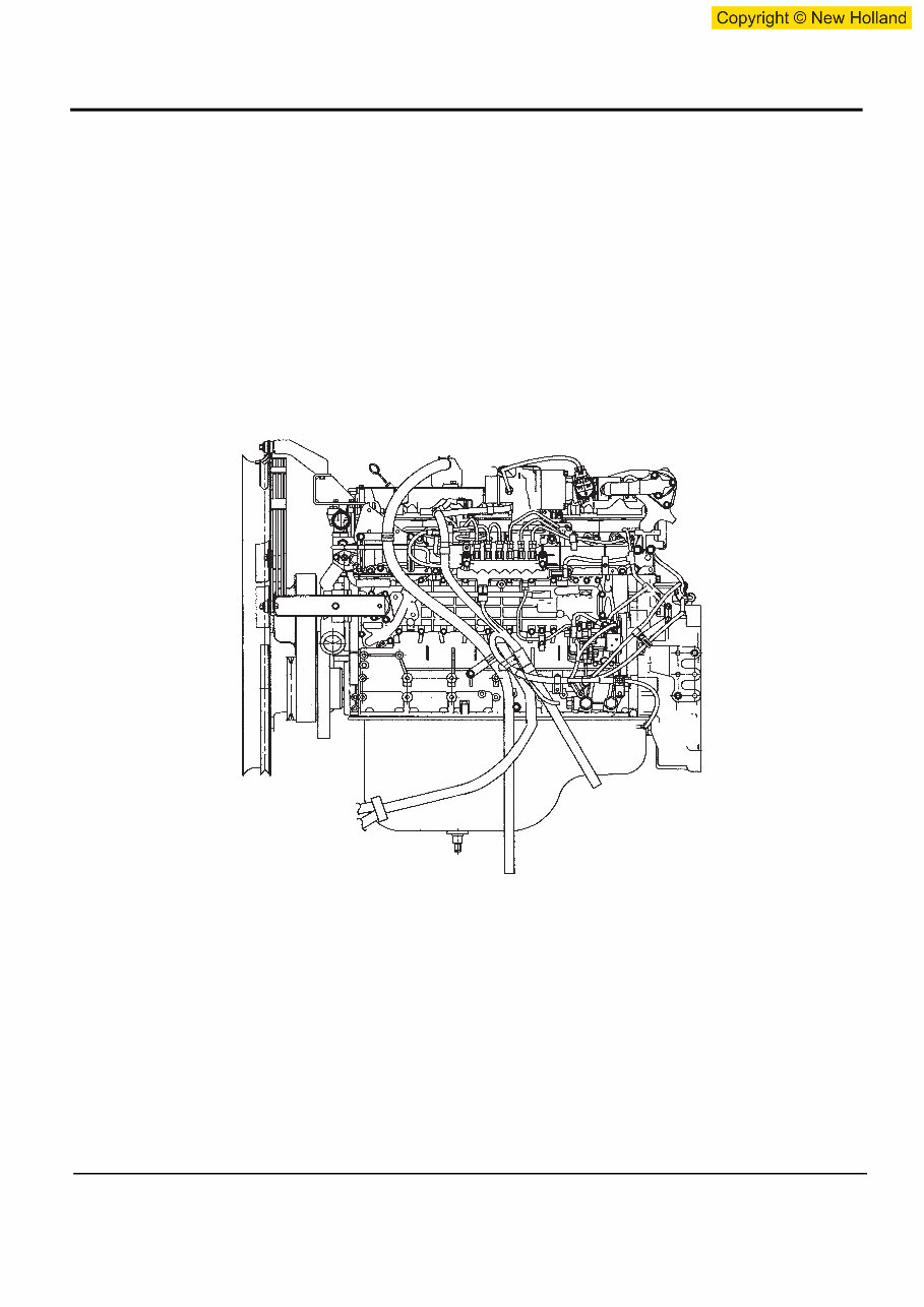
This workshop repair service manual is designed to cover the repair and overhaul of Isuzu 6HK1 Engine cars. It assumes that the technician is fully conversant with general automobile practices and emphasizes the special aspects of the product. The manual includes instructions on components manufactured for Isuzu 6HK1 Engine, as well as repairs of proprietary components. It provides information such as tune-ups, maintenance, removal & install procedures, assemblies & disassemblies, fuel system, ignition, lubrication system, exhaust, electrical system, and body. Additionally, it covers more extensive repairs involving engine and transmission disassembly, and much more.
The manual aims to provide the most reliable information to help both professional mechanics and DIY enthusiasts get the best value from their Isuzu 6HK1 Engine. It includes many of the specifications and procedures available in an authorized Isuzu 6HK1 Engine dealer service department, offering diagnostic and repair procedures for routine maintenance and servicing.
For those intending to do maintenance and repair on their Isuzu 6HK1 Engine, it is essential to use safety equipment and observe safety precautions. The manual also refers to special tools that are recommended or required to accomplish adjustments or repairs, often identified by their Isuzu 6HK1 Engine special tool number and illustrated.
Specification:
This is a FORM NOT A HARD COPY!!!
FAST and FREE ELECTRONIC DELIVERY via Email!!!
Language: English.
Printable: Yes.
File Format: .OVA (for software manuals) or .PDF (for non-software manuals).
General Maintenance Tags for WSMBEST Workshop Service Manuals:
- Air cleaner element renewal
- Air cleaner temperature control check
- Auxiliary drive belt check
- Battery electrolyte level check
- Battery terminal check
- Brake hydraulic fluid renewal
- Brake hydraulic system seal and hose renewal
- Brake pipe and hose check
- Choke adjustment check
- Contact breaker point renewal and distributor lubrication
- Crankcase ventilation system check
- Emission control filter element renewal
- Engine coolant renewal
- Engine idle speed check
- Engine oil and filter renewal
- Engine valve clearance check - OHV engines
- Exhaust system check
- Fluid leak check
- Fluid level checks
- Front and rear brake pad/shoe check
- Front wheel alignment check
- Gearbox oil level check
- Handbrake check
- Hinge and lock check and lubrication
- HT lead, distributor cap, ignition circuit check
- Ignition timing, contact breaker gap (dwell angle) check
- Intensive maintenance
- Mixture adjustment check
- Road test
- Roadwheel security check
- Seat belt check
- Spark plug check and renewal
- Steering and suspension security check
- Throttle damper operation check
- Timing belt renewal
- Tyre checks
- Underbody inspection
- Wiper blade check