

Isuzu 6HK1 6SD1 Common Rail Engine Complete Workshop Service Repair Manual
What's Included?
Fast Download Speeds
Online & Offline Access
Access PDF Contents & Bookmarks
Full Search Facility
Print one or all pages of your manual
June, 2003
Diesel Injection Pump
Common Rail System for ISUZU
Operation
No. E-03-02
SERVICE MANUAL
6HK1/6SD1 Type Engine
00400018
For DENSO Authorized
ECD Service Dealer Only
GENERAL
The common rail system was designed for electronic control of injection quantity, injection tim-
ing and injection pressure to obtain optimal operational control.
Features
• Lower exhaust gas and higher output due to high pressure injection in all usage ranges.
• Reduction in noise and exhaust gas due to injection rate control.
• Improved performance due to increased flexibility in the injection timing setting.
• Independent control of injection pressure in response to engine speed and load.
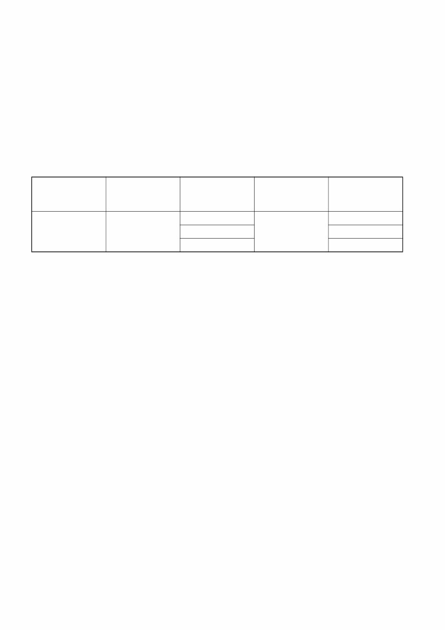
Main Elements
Manufacturer Vehicle Model Engine Model
Cylinder
Configuration
Total
Displacement
(cc)
ISUZU Forward
6HK1
Straight 6
7,800
6SD1 9,800
6WG1 15,600
1
1. Outline
1.1 System Outline
This system also provides the following functions:
• A self-diagnosis and alarm function using computer to diagnose the system’s major
components and alert the driver in the event of a problem.
• A fail-safe function to stop the engine, depending upon the location of the problem.
• A backup function to change the fuel regulation method, thus enabling the vehicle to
continue operation.
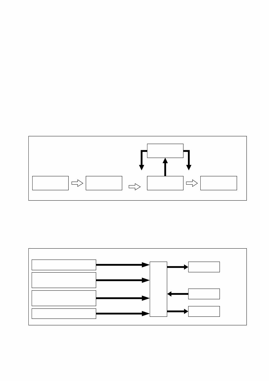
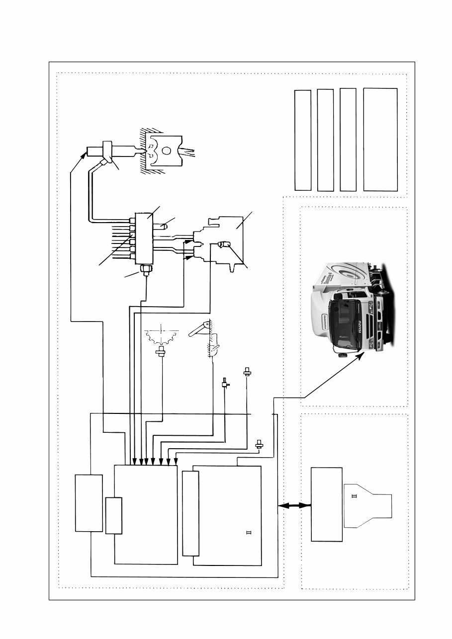
1.2 System Configuration
Divided by function, the system can be classified according to the fuel system and the control
system.
[1] Fuel System
High-pressure fuel that is generated by the supply pump is distributed to the cylinders using a
rail. Electromagnetic valves in the injectors then open and close the nozzle needle valve to con-
trol the start and end of fuel injection.
[2] Control System
Based on the signals received from various sensors mounted on the engine and the vehicle,
the ECU controls current timing and the duration in which the current is applied to the injectors,
thus ensuring an optimal amount of fuel is injected at an optimal time.
The control system can be broadly classified according to the following electronic components:
sensors, computers, and actuators.
Fuel tank Supply pump Rail
Electronic
control
Injector
Discharge
volume
Solenoid valve to control
the needle lift
Q000080E
Sensors Computers Actuators
Accelerator sensor
Injectors
Rail
Supply pump
Other sensors and switches
NE sensor
(Crankshaft position sensor)
TDC sensor
(Cylinder recognition sensor)
(Accelerator opening)
(Engine speed)
Cylinder
recognition signal
Fuel injection quantity
and injection timing control etc.
(Fuel pressure control)
ECU
( )
( )
Q000081E
2
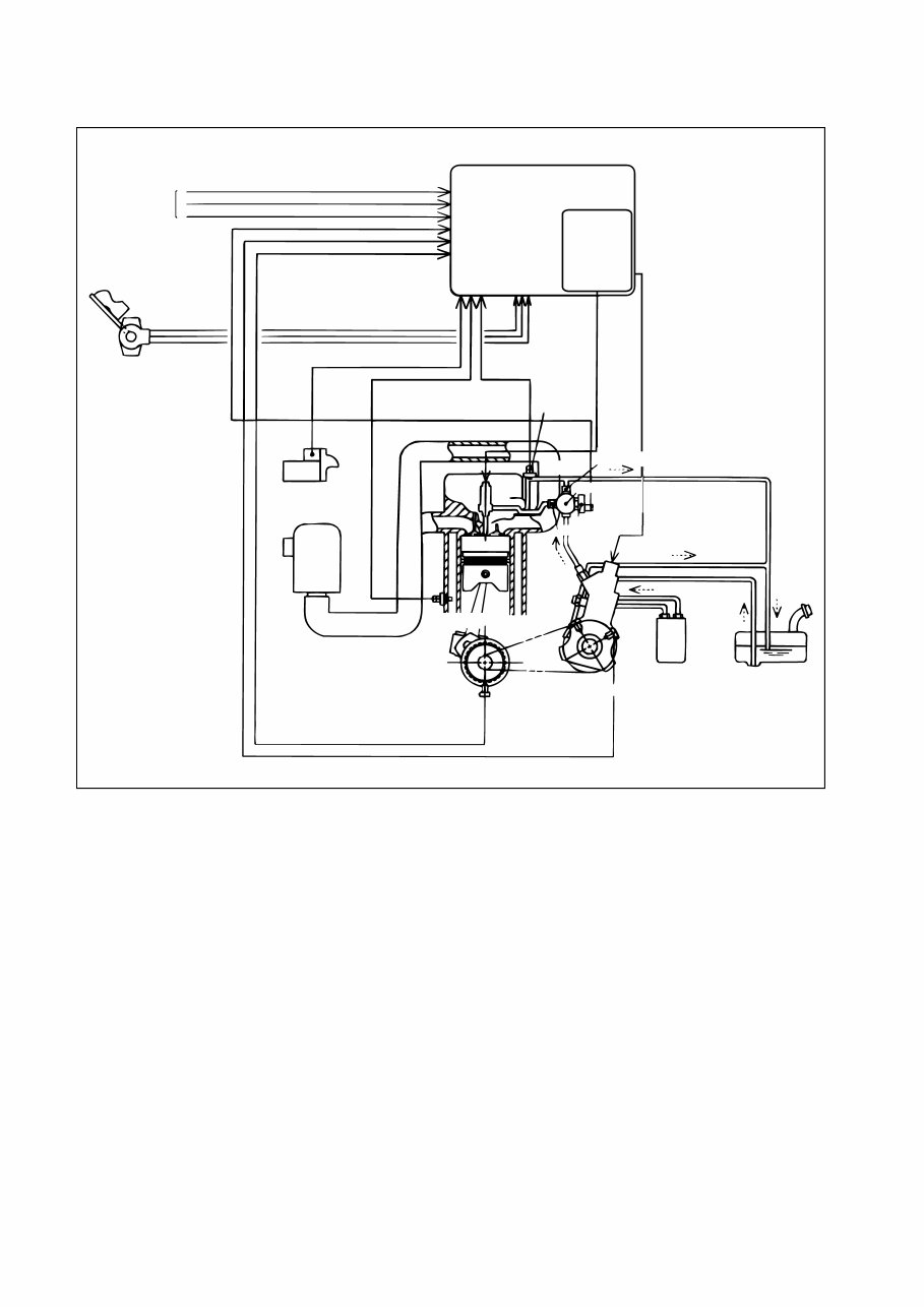
[3] System Configuration (1)
Q000082E
Signals from
switches
ACCP
Accelerator position
sensor
ECU
Charge-up
circuit
Starter signal
Air cleaner
Water temp. sensor
THW THL
STA
Fuel temp.
sensor
Leak pipe
Flow damper
NE sensor
TDC sensor
Fuel filiter
Fuel tank
Supply
pump
Pressure limiter
Rail
3
[4] System Configuration (2)
Q000083E
Fuel
Injection
·Injection Quantity Control
·Injection Timimg Control
·Injection Pressure Control
Engine
Vehicle
·A/T Control
·Exhaust Break Control
·Engine Shut-down control
·TECH COMMUNICATION
Communication
Service Tool
(Scan Tool)
(Dealer)
Rail Pressure sensor
Flow Damper
Injector
(inside Head Cover)
Rail
Pressure Limiter
Crank Position
Sensor (NE Sensor)
Boost Pressure Sensor
Accelerator Position
Sensor
(inside ECU)
·Coolant Temperature Sensor
·Fuel Temperature Sensor
·Atmospheric Air Temperature Sensor
Cylinder Recognition
Sensor (TDC Sensor)
Supply Pump
Injection Rate Control
Injection Quantity Control
Injection Timing Control
Injection Pressure Control
(Pressure Control in Rail)
TECH
ECU
Atmospheric Air
Pressure Sensor
4
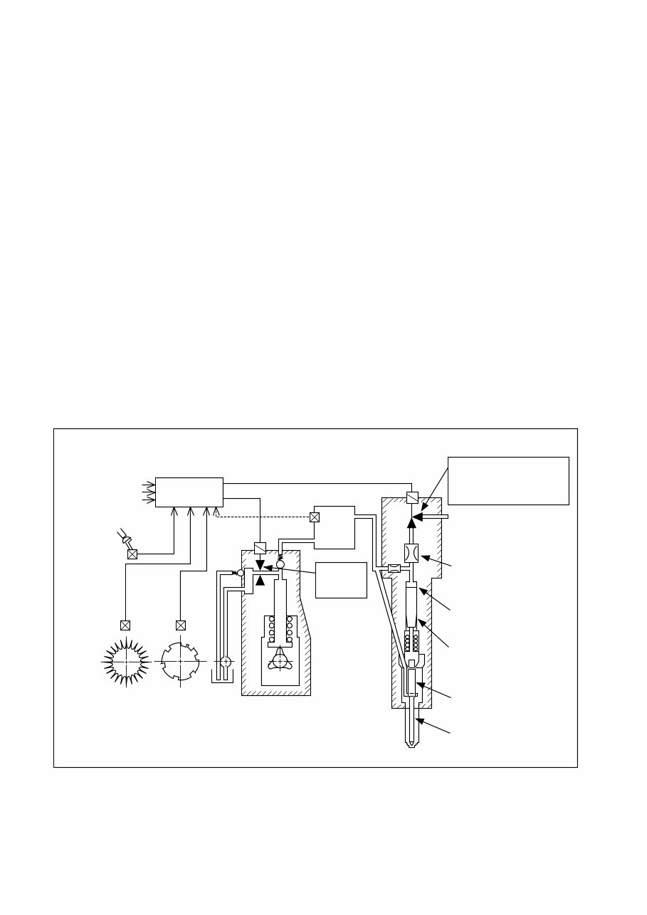
1.3 Construction and Operation of the System
The rail system is comprised of a supply pump, a rail, and injectors, and also includes an ECU
and sensors to regulate those components.
The supply pump generates the internal fuel pressure in the rail. Fuel pressure is regulated by
the quantity of fuel discharged by the supply pump. In turn, the fuel discharge quantity is regu-
lated by electronic signals from the ECU that turn the PCVs (pump control valves) ON and OFF.
Upon receiving fuel pressurized by the supply pump, the rail distributes the fuel to the cylinders.
The pressurized fuel is detected by the rail pressure sensor (installed in the rail) and undergoes
feedback control so that actual pressure will match the command pressure (designated accord-
ing to the engine speed and load).
Pressurized fuel in the rail passes through the injection pipes that lead to the cylinders, and applies
pressure to the injector nozzles and the control chamber.
The injector regulates injection quantity and timing by turning the TWV (two-way valve) ON and OFF.
When the TWV is ON (current applied), the fuel circuit switches over, causing the high-pressure
fuel in the control chamber to flow out via the orifice. As a result, the force of the high-pressure
fuel at the nozzle valve opening causes the needle valve to lift, thus starting the injection of fuel.
When the TWV is turned OFF (current not applied), the fuel circuit switches over so that high-
pressure fuel, traveling via the orifice, is introduced to the control chamber. As a result, the nee-
dle valve lowers, thus ending the injection of fuel.
Thus, through electronic control, the timing of the current applied to the TWV determines the
injection timing, and the duration in which current is applied to the TWV determines the injection
quantity.
Q000084E
Additional information
(temperature, pressure)
Engine load
ECU
Supply Pump
· Injection quantity control
· Injection timing control
· Injection rate control
TWV
Leak
Orifice
Control chamber
Hydraulic piston
Nozzle
Needle
Injector
TWV control pulse
Rail pressure sensor
Rail
Injection
pressure
control
5
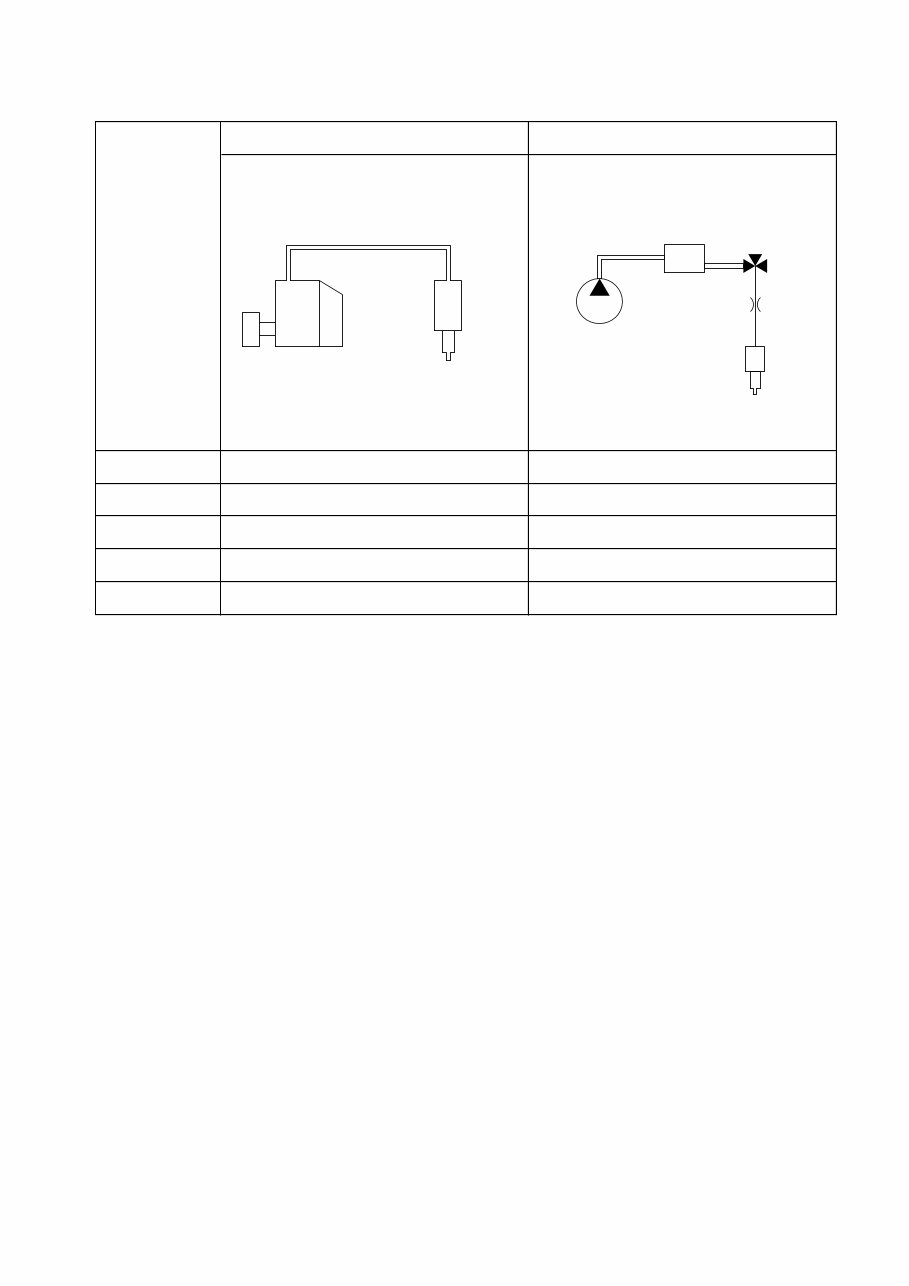
1.4 Comparison to Conventional Pump
Inline Type Common Rail System
System
Injection quantity
regulation
Injection timing
regulation
Distribution of
generated pressure
Distribution
Injection pressure
regulation
Pump (governor)
Pump (timer)
Pump
Pump
(Dependent on engine speed and injection volume)
ECU, injector (TWV)
ECU, injector (TWV)
Supply pump
Supply pump (PCV)
Rail
Q000085E
Pipe
Instantaneous high
pressure
Timer
Pump
Governor
Nozzle
Supply pump
Rail
Constant high
pressure
Injector
6
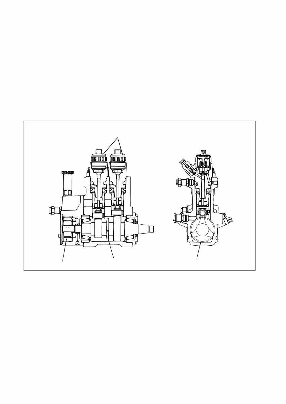
2. Construction and Operation of Components
2.1 Supply Pump
[1] Outline
The function of the supply pump is to regulate the fuel discharge volume, thus generating internal
fuel pressure in the rail.
[2] Construction
The supply pump consists of a feed pump, similar to that of the conventional in-line pump, and
the PCVs (pump control valves), provided at each cylinder, to regulate the fuel discharge volume.
The supply pump uses a three-lobe cam to reduce the number of engine cylinders supplied by
the pump to one-third (e.g. a two-cylinder pump for a six-cylinder engine). Furthermore,
smooth and stable rail pressure is obtained because the rate at which fuel is pumped to the rail
is the same as the injection rate.
Q000086E
3-lobe cam
PCV (Pump Control Valve)
Gear of TDC sensor
Feed pump
7
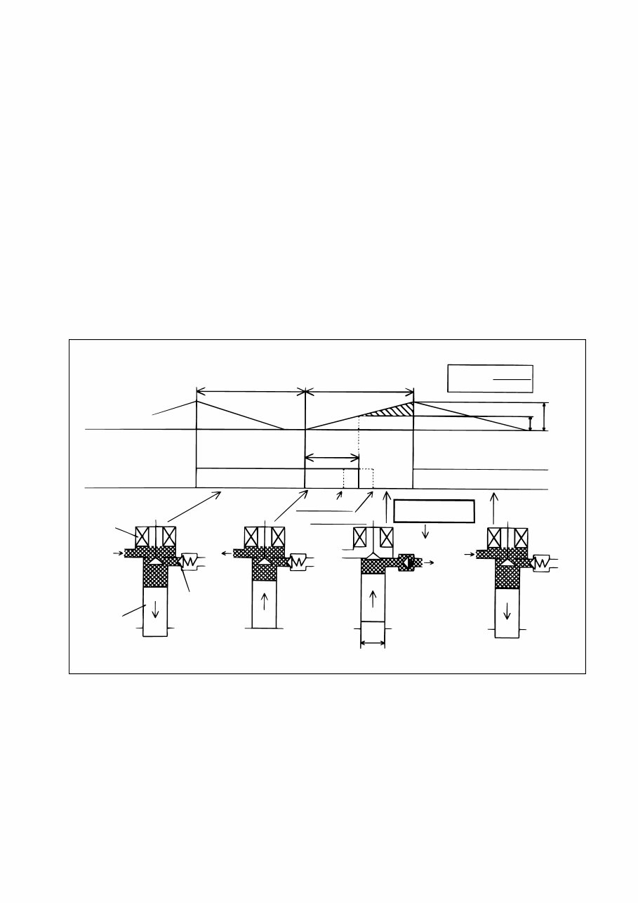
[3] Operation
A: The PCV remains open during the plunger’s downward stroke, allowing low-pressure fuel to
be drawn into the plunger chamber by way of the PCV.
B: If the valve remains open because current is not applied to the PCV, even after the plunger
begins its upward stroke, the fuel that was drawn in returns via the PCV, without being pres-
surized.
C: When current is applied to the PCV in order to close the valve at the timing that accommo-
dates the required discharge volume, the return passage closes, causing pressure in the
plunger chamber to rise. The fuel then passes through the delivery valve (check valve) to the
rail. As a result, an amount of fuel that corresponding to the plunger lift after the PCV closes
becomes the discharge volume, and varying the timing of the PCV closure (plunger pre-
stroke) varies the discharge volume, thus regulating rail pressure.
A’: After surpassing the maximum cam lift, the plunger begins its downward stroke, causing
pressure in the plunger chamber to decrease. At this time, the delivery valve closes, thus
stopping the pumping of the fuel. In addition, because current to the PCV valve is cut off, the
PCV opens, allowing low-pressure fuel to be drawn into the plunger chamber. Thus, the
pump assumes condition “A”.
Q000087E
Suction process Delivery process
Cam lift
Valve open
Pre-stroke
PCV
operation
Valve
closed
H
h
Increasing
dischargevolume
Reducing discharge volume
Discharging required
dischrge volume
Rail
Pump operation
PCV
Plunger
Delivery valve
A B C A'
φd
Discharge
volume
Q=
πd
2
(H-h)
4
8
[4] PCV (pump control valve)
The PCV regulates the volume of fuel discharged by the supply pump in order to regulate rail
pressure. The volume of fuel discharged by the supply pump to the rail is determined by the
time at which current is applied to the PCV.
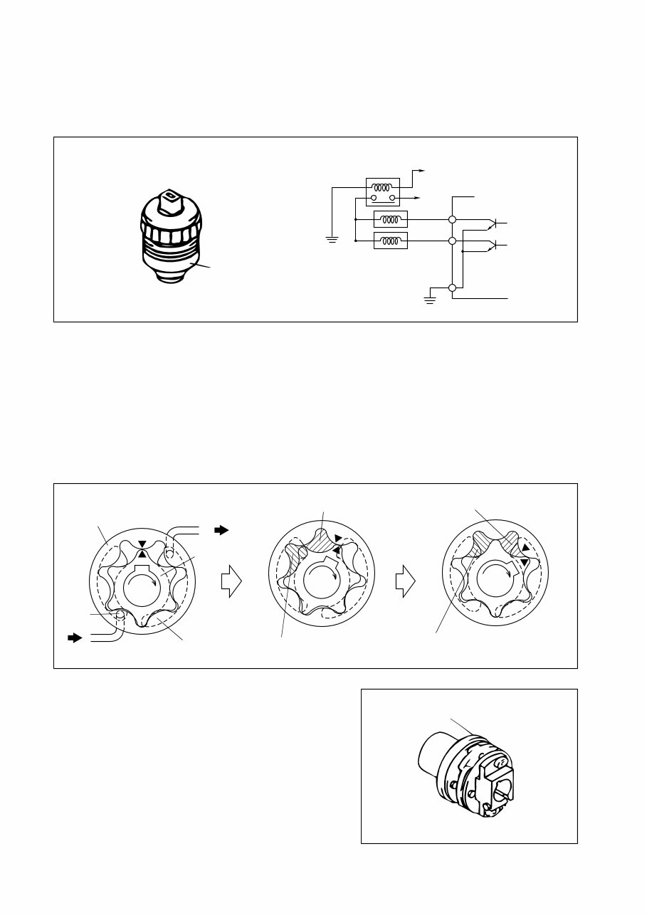
[5] Trochoid Type Feed Pump
The feed pump, which is housed in the supply pump, draws fuel up from the tank and delivers
it to the chamber via the fuel filter. The feed pump rotor is driven by the camshaft.
The rotation of the camshaft causes the outer and inner rotors to rotate. At this time, the suction
port side pump chamber volume (the space surrounded by the outer and inner rotors) increases
gradually, causing the fuel entering from the fuel inlet to be drawn into the pump chamber via
the suction port. Along with the rotation of the rotor, the fuel that has been drawn in moves to-
wards the discharge port and is discharged. The discharged fuel travels via the fuel outlet and
is fed into the supply pump body.
[6] Coupling
The coupling is an intermediary device that transmits
the engine driving torque to the supply pump camshaft.
Key switch PCV relay
+B
PCV1
PCV2
Q000088E
ECU
PCV
Q000090E
Outer rotor
To pump chamber
Inner rotor
Discharge port
From fuel tank
Suction
port
Volume decreased
(while moving to discharge port)
Volume increased
(while drawing in fiel)
Volume increased
(while drawing in fiel)
Volume decreased
(while discharging fuel to discharge port)
Coupling
Q000091E
You're Reading a Preview
What's Included?
Fast Download Speeds
Online & Offline Access
Access PDF Contents & Bookmarks
Full Search Facility
Print one or all pages of your manual
$41.99
Viewed 48 Times Today


Secure transaction
What's Included?
Fast Download Speeds
Online & Offline Access
Access PDF Contents & Bookmarks
Full Search Facility
Print one or all pages of your manual
$41.99
Thank you for considering this comprehensive Workshop Service Repair Manual for the Isuzu 6HK1 6SD1 Common Rail Engine.
This manual is an invaluable resource covering every Service & Repair Procedure necessary for professional mechanics and DIY enthusiasts alike.
With easy-to-follow step-by-step instructions and detailed pictures, this manual empowers you to save significant costs by performing your own repairs.
Upon acquisition, this manual becomes your perpetual asset, allowing you to print individual pages, chapters, or the entire document. It is also compatible for viewing on tablets and smartphones.
MODELS COVERED:
- All Models/Engines/Trim/Transmissions Types Are Covered
CONTENTS:
- This high-quality Service Repair Workshop Manual encompasses all repair procedures from A to Z, ensuring comprehensive coverage of every repair and service procedure.
COMPUTER REQUIREMENTS:
- This manual is compatible with all PC & MAC Computers, tablets, and mobile phones. The only software required is Adobe Reader, which is typically pre-installed on most computers or can be downloaded for free.
INSTANT DELIVERY:
- Upon payment confirmation via Visa, MasterCard, or PayPal, the manual will be instantly emailed to the address provided during checkout.
Customer Satisfaction Guaranteed.


