

ISUZU 4HK1 -6HK1 Engine Electrical Toubleshooting manual
What's Included?
Fast Download Speeds
Online & Offline Access
Access PDF Contents & Bookmarks
Full Search Facility
Print one or all pages of your manual
TROUBLESHOOTING MANUAL
4HK1-6HK1 ISUZU ENGINE
Workshop manual integration of the following models:
E385 (Tier 3)
R3807
R3807
All information, illustrations and specifications in this manual are based on the latest product information available at
the time of publication.
The right is reserved to make changes at any time without notice.
NEW HOLLAND KOBELCO CONSTRUCTION MACHINERY S.p.A. - PRODUCT SUPPORT
FORM No. 604.13.654 - Edition - January 2006


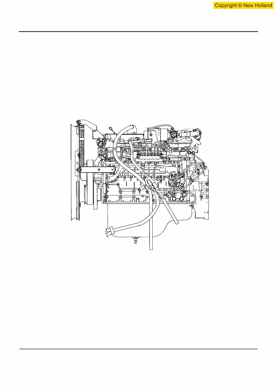
Introduction
This Troubleshooting Manual describes the structure and the troubleshooting of
electronic control fuel injection system (common rail type) in 4HK1 and 6HK1
industrial engines.
Use this manual sufficiently to perform service work properly and quickly.
For any question or comment, or should you notice any mistake concerning the
content of this manual, please contact:
NEW HOLLAND KOBELCO
CONSTRUCTION MACHINERY
Strada Settimo, 323
San Mauro Torinese (TO)
10099 ITALIA
PRODUCT SUPPORT
Fax ++39 011 0077357


Control System
Engine Control
(Electronic control fuel injection system (Common rail type))
Table of Contents
How to use this manual . . . . . . . . . . . . . . . . . . 1E-3
Table of abbreviation . . . . . . . . . . . . . . . . . . . . 1E-4
List of parts according to engine control specifications
. . . . . . . . . . . . . . . . . . . . . . . . . . . . . . . . . . . . . 1E-5
About colors of wirings . . . . . . . . . . . . . . . . . . . 1E-6
About wiring diagrams . . . . . . . . . . . . . . . . . . . 1E-7
How to read trouble diagnosis section . . . . . . . 1E-8
Precautions on Service Work . . . . . . . . . . . . . 1E-10
Procedure of trouble diagnosis . . . . . . . . . . . 1E-11
Interview . . . . . . . . . . . . . . . . . . . . . . . . . . . . . 1E-13
Pre-inspection . . . . . . . . . . . . . . . . . . . . . . . . 1E-15
Trouble Diagnosis . . . . . . . . . . . . . . . . . . . . . 1E-15
How to read DTC . . . . . . . . . . . . . . . . . . . . . . 1E-16
Confirmation after repair . . . . . . . . . . . . . . . . 1E-18
List of final check items . . . . . . . . . . . . . . . . . 1E-18
How to clear DTC . . . . . . . . . . . . . . . . . . . . . . 1E-19
CNH - EST Diagnostic tool . . . . . . . . . . . . . . . 1E-20
How to Inspect Injector . . . . . . . . . . . . . . . . . . 1E-22
How to use injector checker . . . . . . . . . . . . . . 1E-22
Method to identify using non-contact infrared
thermometer . . . . . . . . . . . . . . . . . . . . . . . . . . 1E-26
How to use flash tool . . . . . . . . . . . . . . . . . . . . . 1E-28
Introduction . . . . . . . . . . . . . . . . . . . . . . . . . . 1E-28
Cautions . . . . . . . . . . . . . . . . . . . . . . . . . . . . . 1E-29
EMPS Component Parts . . . . . . . . . . . . . . . . 1E-31
ECM (Hardware) Compatibility . . . . . . . . . . . . 1E-32
System Requirements for EMPS Software
(Recommended) . . . . . . . . . . . . . . . . . . . . . . 1E-32
EMPS (Software) Setup Procedure . . . . . . . . 1E-33
EMPS Operation Procedure . . . . . . . . . . . . . . 1E-37
How to use breaker box . . . . . . . . . . . . . . . . . . 1E-79
Engine Control System . . . . . . . . . . . . . . . . . . . 1E-82
Description of function and operation . . . . . . . 1E-82
Engine Control Module (ECM) . . . . . . . . . . . . 1E-91
Circuit diagram . . . . . . . . . . . . . . . . . . . . . . . 1E-112
Engine harness location . . . . . . . . . . . . . . . . 1E-128
Connector list . . . . . . . . . . . . . . . . . . . . . . . . 1E-140
List of function checks . . . . . . . . . . . . . . . . . . . 1E-143
OBD system check . . . . . . . . . . . . . . . . . . . . 1E-144
Diagnosis lamp illumination circuit system
check . . . . . . . . . . . . . . . . . . . . . . . . . . . . . . 1E-146
Diagnosis lamp blinking circuit system check 1E-148
Scan tool power supply circuit system check 1E-151
Scan tool communication circuit system
check . . . . . . . . . . . . . . . . . . . . . . . . . . . . . . 1E-153
Starting circuit system check . . . . . . . . . . . . 1E-156
Starting system check . . . . . . . . . . . . . . . . . 1E-162
Fuel system check . . . . . . . . . . . . . . . . . . . . 1E-165
Intake system check . . . . . . . . . . . . . . . . . . . 1E-167
Exhaust system check . . . . . . . . . . . . . . . . . 1E-168
EGR control system check . . . . . . . . . . . . . . 1E-169
QOS system check . . . . . . . . . . . . . . . . . . . . 1E-172
List of diagnostic trouble code . . . . . . . . . . . . . 1E-177
DTC: P0087 (Flash code 227) Common rail low
pressure fault (No pressure feed in supply
pump) . . . . . . . . . . . . . . . . . . . . . . . . . . . . . . 1E-201
DTC: P0088 (Flash code 118) Common rail pressure
is abnormally high (1st or 2nd stage) . . . . . . 1E-209
DTC: P0089 (Flash code 151) Common rail pressure
fault (Excessive pressure feed in supply
pump) . . . . . . . . . . . . . . . . . . . . . . . . . . . . . . 1E-214
DTC: P0090 (Flash code 247) SCV drive system
open circuit, +B short or ground short . . . . . 1E-219
DTC: P0107 (Flash code 71) Barometric pressure
sensor circuit input is low (open circuit or ground
short). . . . . . . . . . . . . . . . . . . . . . . . . . . . . . . 1E-225
DTC: P0108 (Flash code 71) Barometric pressure
sensor circuit input is high (+5 V short) . . . . 1E-232
DTC: P0112 (Flash code 22) Intake air temperature
sensor fault (low voltage fault, GND short, short
circuit) . . . . . . . . . . . . . . . . . . . . . . . . . . . . . . 1E-239
DTC: P0113 (Flash code 22) Intake air temperature
sensor fault (high voltage fault, open circuit or short to
power supply circuit) . . . . . . . . . . . . . . . . . . . 1E-245
DTC: P0117 (Flash code 23) Engine coolant
temperature sensor fault (low voltage fault, GND
short, short circuit) . . . . . . . . . . . . . . . . . . . . 1E-253
DTC: P0118 (Flash code 23) Engine coolant
temperature sensor input is high (open circuit or short
to power supply) . . . . . . . . . . . . . . . . . . . . . . 1E-260
DTC: P0182 (Flash code 211) Fuel temperature
sensor fault (low voltage fault, GND short) . . 1E-268
DTC: P0183 (Flash code 211) Fuel temperature
sensor fault (high voltage fault, open circuit or short to
power supply circuit) . . . . . . . . . . . . . . . . . . . 1E-274
DTC: P0192 (Flash code 245) Common rail pressure
sensor fault (low voltage fault, short circuit) . 1E-282
DTC: P0193 (Flash code 245) Common rail pressure
sensor fault (high voltage fault) . . . . . . . . . . 1E-288
DTC: P0201 (Flash code 271) Open circuit in
injection nozzle #1 drive system . . . . . . . . . . 1E-295
DTC: P0202 (Flash code 272) Open circuit in
injection nozzle #2 drive system . . . . . . . . . . 1E-302
DTC: P0203 (Flash code 273) Open circuit in
injection nozzle #3 drive system . . . . . . . . . . 1E-309
DTC: P0204 (Flash code 274) Open circuit in
injection nozzle #4 drive system . . . . . . . . . . 1E-316

1E-2 Electronic control fuel injection system (Common rail type)
DTC: P0205 (Flash code 275) Open circuit in
injection nozzle #5 drive system . . . . . . . . . 1E-323
DTC: P0206 (Flash code 276) Open circuit in
injection nozzle #6 drive system . . . . . . . . . 1E-328
DTC: P0219 (Flash code 543) Overrun . . . . 1E-333
DTC: P0237 (Flash code 32) Boost sensor pressure
fault (low voltage fault, open circuit) . . . . . . . 1E-335
DTC: P0238 (Flash code 32) Boost pressure sensor
fault (high voltage fault, short to power supply circuit,
ground open circuit) . . . . . . . . . . . . . . . . . . . 1E-343
DTC: P0335 (Flash code 15) Crank sensor fault (no
signal) . . . . . . . . . . . . . . . . . . . . . . . . . . . . . . 1E-351
DTC: P0336 (Flash code 15) Crank sensor fault
(signal fault) . . . . . . . . . . . . . . . . . . . . . . . . . 1E-358
DTC: P0340 (Flash code 14) Cam sensor fault (no
signal) . . . . . . . . . . . . . . . . . . . . . . . . . . . . . . 1E-364
DTC: P0341 (Flash code 14) Cam sensor fault (signal
fault) . . . . . . . . . . . . . . . . . . . . . . . . . . . . . . . 1E-371
DTC: P0380 (Flash code 66) Glow relay circuit
fault . . . . . . . . . . . . . . . . . . . . . . . . . . . . . . . 1E-377
DTC: P0381 (Flash code 67) Glow plug lamp circuit
fault . . . . . . . . . . . . . . . . . . . . . . . . . . . . . . . 1E-382
DTC: P0487 (Flash code 44) EGR position sensor
fault . . . . . . . . . . . . . . . . . . . . . . . . . . . . . . . 1E-387
DTC: P0488 (Flash code 45) EGR valve control
fault . . . . . . . . . . . . . . . . . . . . . . . . . . . . . . . 1E-393
DTC: P0522 (Flash code 294) Engine oil pressure
sensor fault (low voltage fault, open circuit, ground
short) . . . . . . . . . . . . . . . . . . . . . . . . . . . . . . 1E-399
DTC: P0523 (Flash code 295) Engine oil pressure
sensor fault (high voltage fault, short to power supply,
ground short) . . . . . . . . . . . . . . . . . . . . . . . . 1E-405
DTC: P0601 (Flash code 53) ROM fault . . . 1E-413
DTC: P0603 (Flash code 54) EEPROM fault 1E-415
DTC: P0606 (Flash code 51/52) CPU fault . 1E-417
DTC: P0611 (Flash code 34) Charge circuit fault
(bank 1) . . . . . . . . . . . . . . . . . . . . . . . . . . . . 1E-419
DTC: P0612 (Flash code 34) Charge circuit fault
(bank 2) . . . . . . . . . . . . . . . . . . . . . . . . . . . . 1E-422
DTC: P0650 (Flash code 77) Diagnosis lamp circuit
fault . . . . . . . . . . . . . . . . . . . . . . . . . . . . . . . 1E-425
DTC: P1093 (Flash code 227) No pump pressure
feed . . . . . . . . . . . . . . . . . . . . . . . . . . . . . . . 1E-430
DTC: P1095 (Flash code 225) Pressure limiter
open . . . . . . . . . . . . . . . . . . . . . . . . . . . . . . . 1E-439
DTC: P1112 (Flash code 295) Boost temperature
sensor fault (low voltage fault, ground short) 1E-449
DTC: P1113 (Flash code 295) Boost temperature
sensor fault (high voltage fault, open circuit, short to
power supply circuit) . . . . . . . . . . . . . . . . . . 1E-457
DTC: P1173 (Flash code 542) Overheat . . . 1E-463
DTC: P1225 (Flash code 31) Idle UP/DOWN switch
fault . . . . . . . . . . . . . . . . . . . . . . . . . . . . . . . 1E-469
DTC: P1261 (Flash code 158) Injection nozzle
common 1 drive system fault . . . . . . . . . . . . 1E-473
DTC: P1262 (Flash code 159) Injection nozzle
common 2 drive system fault . . . . . . . . . . . . 1E-484
DTC: P1271 (Flash code 24) Accelerator sensor 1-2
comparison fault . . . . . . . . . . . . . . . . . . . . . . 1E-495
DTC: P1277 (Flash code 24) Accelerator sensor 1
fault (low voltage fault) . . . . . . . . . . . . . . . . . 1E-501
DTC: P1278 (Flash code 24) Accelerator sensor 1
fault (high voltage fault) . . . . . . . . . . . . . . . . 1E-506
DTC: P1282 (Flash code 24) Accelerator sensor 2
fault (low voltage fault) . . . . . . . . . . . . . . . . . 1E-511
DTC: P1283 (Flash code 24) Accelerator sensor 2
fault (high voltage fault) . . . . . . . . . . . . . . . . 1E-516
DTC: P1345 (Flash code 16) Cam sensor out of
phase . . . . . . . . . . . . . . . . . . . . . . . . . . . . . . 1E-521
DTC: P1625 (Flash code 416) Main relay
fault . . . . . . . . . . . . . . . . . . . . . . . . . . . . . . . . 1E-526
DTC: P1630 (Flash code 36) A/D conversion
fault . . . . . . . . . . . . . . . . . . . . . . . . . . . . . . . . 1E-533
DTC: P1631 (Flash code 55) Voltage fault in 5-V
power supply 1 . . . . . . . . . . . . . . . . . . . . . . . 1E-535
DTC: P1632 (Flash code 55) Voltage fault in 5-V
power supply 2 . . . . . . . . . . . . . . . . . . . . . . . 1E-538
DTC: P1633 (Flash code 55) Voltage fault in 5-V
power supply 3 . . . . . . . . . . . . . . . . . . . . . . . 1E-541
DTC: P1634 (Flash code 55) Voltage fault in 5-V
power supply 4 . . . . . . . . . . . . . . . . . . . . . . . 1E-544
DTC: P1635 (Flash code 55) Voltage fault in 5-V
power supply 5 . . . . . . . . . . . . . . . . . . . . . . . 1E-550
List of trouble symptom . . . . . . . . . . . . . . . . . . 1E-551
Engine start failure . . . . . . . . . . . . . . . . . . . . 1E-555
Engine stall . . . . . . . . . . . . . . . . . . . . . . . . . . 1E-565
Engine hunting, rough idling . . . . . . . . . . . . . 1E-559
Engine output shortage . . . . . . . . . . . . . . . . 1E-563
Exhaust gas contains a lot of white smoke. . 1E-568
Exhaust gas contains a lot of black smoke. . 1E-571
Noise . . . . . . . . . . . . . . . . . . . . . . . . . . . . . . 1E-574
Fuel consumption deteriorates. . . . . . . . . . . 1E-576
Oil consumption deteriorates. . . . . . . . . . . . . 1E-579
Special Tool . . . . . . . . . . . . . . . . . . . . . . . . . . . 1E-581

Electronic control fuel injection system (Common rail type) 1E-3
How to use this manual
This manual describes about engine-related trouble diagnosis, and is closely related
to the machine trouble diagnosis. Always refer to both manuals for the trouble
diagnosis.
This manual consists of the following contents. This section “How to use this manual”
describes about abbreviations and instructions to use this manual. Therefore, if you
are familiar with Isuzu manuals, start with Precautions on service work and Basic
procedure of trouble diagnosis.
How to use this manual
• Table of abbreviation
• List of parts according to engine control specifications
• Wiring color code
• How to use wiring diagram
Precautions on service work
Procedure of trouble diagnosis
How to use trouble diagnosis-related tool
• How to use injector checker
• How to use flash tool
• How to use breaker box
Engine control system
List of function checks
List of diagnostic trouble codes
List of trouble symptom
1E-4 Electronic control fuel injection system (Common rail type)
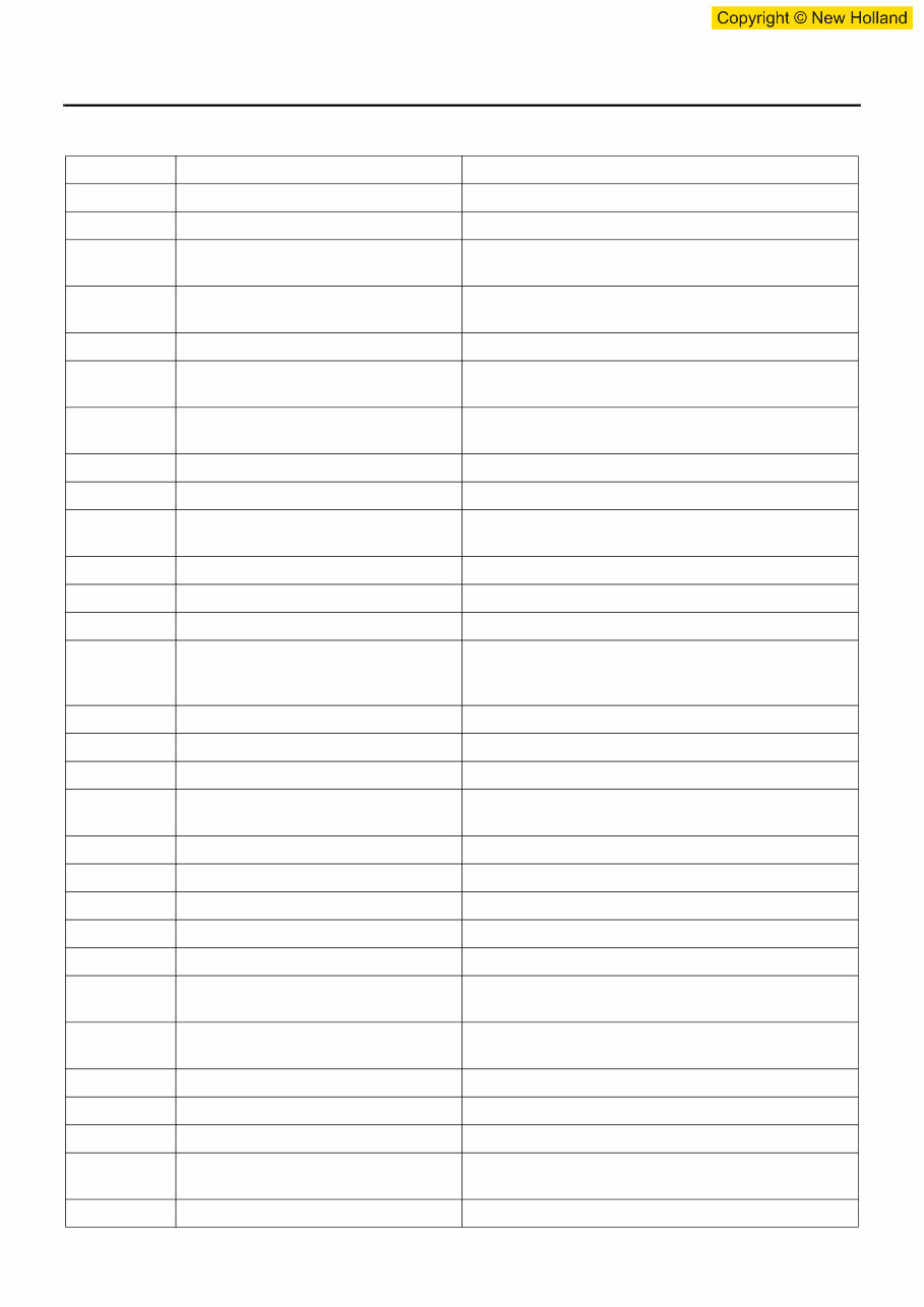
Table of abbreviation
Abbreviation Name Meaning and remarks
A/D Analog/Digital Analog/Digital
AP Accelerator Position Accelerator opening angle
CAN Controller Area Network Communication system used to communicate between
ECM and the machine control unit
CKP Crankshaft Position Crankshaft (the sensor is installed onto flywheel
housing) position
C/U Control/Unit Abbreviation of control unit
CMP Camshaft Position Camshaft (the sensor is installed onto the rear of
cylinder head) position
DLC Data Link Connector Connector for scan tool (also known as: Checker
connector)
EMPS Engine Module Programming System Rewriting of control program in ECM
DMM Digital Multi-Meter Diagnostic tester for electrical equipment system
DTC Diagnostic Trouble Code Self-diagnosis code numbers which indicate trouble
condition
ECT Engine Coolant Temperature Engine coolant temperature
ECM Engine Control Module Core of engine control in engine control computer
ECU Electronic Control Unit Computer for various control
EGR Exhaust Gas Recirculation Recirculation system which mixes exhaust gas from
engine with intake air again to lower the combustion
temperature resulting in reduction of NOx.
EMI Electro Magnetic Interference Electro Magnetic Interference
Exh Exhaust Exhaust
F/B Feed/Back Abbreviation of feedback
FT Fuel Temperature Fuel temperature (the sensor is installed onto supply
pump.)
GND Ground Ground/Earth
IAT Intake Air Temperature Intake air temperature
J/C Joint/Connection Connector which connects each harness
MIL Malfunction Indicator Lamp Warning lamp MIL (diagnosis lamp)
PC Pressure Control Pressure control/Common rail pressure
SCV Suction Control Valve Valve which controls fuel flow to common rail and is
installed onto supply pump
PCV Pressure Control Valve Valve which controls fuel flow to common rail and is
installed onto supply pump
PWM Pulse Width Modulation Pulse width modulated wave
QOS Quick On Start Warming-up device
RP Rail Pressure Pressure in common rail
SBF Slow Blow Fuse Slow-blow type fuse which protects circuits of battery,
motor, etc.
SIG Signal Signal
Electronic control fuel injection system (Common rail type) 1E-5
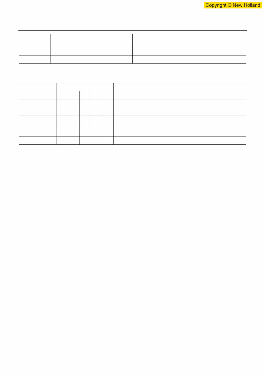
List of parts according to engine control specifications
VSS Vehicle Speed Sensor Sensor used to detect vehicle speed to control meters
or engine
W/S Weld/Splice Joint of each harness without connector
Engine
Function
6W 6U 6H 4H 4J
PCV m m Controls the fuel pressure feed of supply pump.
SCV m m m Controls the fuel pressure feed of supply pump.
CMP sensor m m m Detects camshaft position of engine (used for identifying cylinder.)
G sensor
m m
Detects cam position of supply pump (used for identifying
cylinder.)
CKP sensor m m m m m Detects crankshaft position (used for engine control in general.)
Abbreviation Name Meaning and remarks
You're Reading a Preview
What's Included?
Fast Download Speeds
Online & Offline Access
Access PDF Contents & Bookmarks
Full Search Facility
Print one or all pages of your manual
$31.99
Viewed 58 Times Today


Secure transaction
What's Included?
Fast Download Speeds
Online & Offline Access
Access PDF Contents & Bookmarks
Full Search Facility
Print one or all pages of your manual
$31.99
This Troubleshooting Manual provides detailed information on the structure and troubleshooting of the electronic control fuel injection system (common rail type) in 4HK1 and 6HK1 industrial engines. It is a valuable resource for both professional mechanics and DIY enthusiasts, enabling them to perform service work efficiently.
The manual includes electrical diagrams and is applicable to the following models:
- 4HK1-6HK1 Isuzu Diesel Engine
The table of contents covers the following topics:
- Engine Control (Common rail type)
- How to use this manual
- Precautions on Service Work
- Procedure of trouble diagnosis
- How to Inspect Injector
- How to use flash tool
- How to use breaker box
- Engine Control System
- List of function checks
- List of diagnostic trouble code
- Special Tool
- CNH - EST Diagnostic tool
The manual is available in English and comes in a file format with a total of 580+ pages.


