

HITACHI ISUZU 4H & 6H Engine Service Manual
What's Included?
Fast Download Speeds
Online & Offline Access
Access PDF Contents & Bookmarks
Full Search Facility
Print one or all pages of your manual

Introduction
This Troubleshooting Manual describes the structure and the troubleshooting of
electronic control fuel injection system (common rail type) in 4HK1 and 6HK1
industrial engines.
Use this manual sufficiently to perform service work properly and quickly.
Isuzu Motors Limited
Off-highway Powertrain
Operation Dept.


Control System
Engine Control
(Electronic control fuel injection system (Common rail type))
Table of Contents
How to use this manual . . . . . . . . . . . . . . . . . . . . 1E-3
Table of abbreviation . . . . . . . . . . . . . . . . . . . . . 1E-4
List of parts according to engine control specifications
. . . . . . . . . . . . . . . . . . . . . . . . . . . . . . . . . . . . . 1E-5
About colors of wirings . . . . . . . . . . . . . . . . . . . 1E-6
About wiring diagrams. . . . . . . . . . . . . . . . . . . . 1E-7
Precautions on Service Work . . . . . . . . . . . . . . . 1E-10
Procedure of trouble diagnosis . . . . . . . . . . . . . 1E-11
Interview . . . . . . . . . . . . . . . . . . . . . . . . . . . . . 1E-13
Pre-inspection . . . . . . . . . . . . . . . . . . . . . . . . . 1E-15
Trouble Diagnosis . . . . . . . . . . . . . . . . . . . . . . 1E-15
How to read DTC . . . . . . . . . . . . . . . . . . . . . . 1E-16
Confirmation after repair . . . . . . . . . . . . . . . . . 1E-18
List of final check items . . . . . . . . . . . . . . . . . . 1E-18
How to clear DTC . . . . . . . . . . . . . . . . . . . . . . 1E-19
Trouble diagnosis with scan tool . . . . . . . . . . . 1E-20
How to use trouble diagnosis-related tool . . . . . 1E-25
How to use Tech2 . . . . . . . . . . . . . . . . . . . . . . 1E-25
Injector balance test . . . . . . . . . . . . . . . . . . . . 1E-43
Rewrite setting of Q adjust data by Tech2. . . . 1E-48
How to use TIS 2000. . . . . . . . . . . . . . . . . . . . 1E-68
How to Inspect Injector. . . . . . . . . . . . . . . . . . . . 1E-78
How to use injector checker . . . . . . . . . . . . . . 1E-78
Method to identify using non-contact infrared
thermometer . . . . . . . . . . . . . . . . . . . . . . . . . . 1E-82
How to use flash tool . . . . . . . . . . . . . . . . . . . . 1E-84
How to use breaker box . . . . . . . . . . . . . . . . . 1E-85
Engine Control System . . . . . . . . . . . . . . . . . . . 1E-88
Description of function and operation . . . . . . . 1E-88
Engine Control Module (ECM) . . . . . . . . . . . . 1E-97
Circuit diagram . . . . . . . . . . . . . . . . . . . . . . . 1E-118
Engine harness location . . . . . . . . . . . . . . . . 1E-134
Connector list . . . . . . . . . . . . . . . . . . . . . . . . 1E-146
List of function checks . . . . . . . . . . . . . . . . . . . 1E-149
OBD system check . . . . . . . . . . . . . . . . . . . . 1E-150
Diagnosis lamp illumination circuit system check
. . . . . . . . . . . . . . . . . . . . . . . . . . . . . . . . . . . 1E-152
Diagnosis lamp blinking circuit system check
. . . . . . . . . . . . . . . . . . . . . . . . . . . . . . . . . . . 1E-154
Scan tool power supply circuit system check 1E-157
Scan tool communication circuit system check
. . . . . . . . . . . . . . . . . . . . . . . . . . . . . . . . . . . 1E-159
Starting circuit system check . . . . . . . . . . . . . 1E-162
Starting system check . . . . . . . . . . . . . . . . . . 1E-168
Fuel system check . . . . . . . . . . . . . . . . . . . . 1E-171
Intake system check . . . . . . . . . . . . . . . . . . . 1E-173
Exhaust system check . . . . . . . . . . . . . . . . . 1E-174
EGR control system check . . . . . . . . . . . . . . 1E-175
QOS system check . . . . . . . . . . . . . . . . . . . . 1E-178
List of diagnostic trouble code . . . . . . . . . . . . . 1E-183
DTC: P0087 (Flash code 227) Common rail low
pressure fault (No pressure feed in supply pump)
. . . . . . . . . . . . . . . . . . . . . . . . . . . . . . . . . . . 1E-207
DTC: P0088 (Flash code 118) Common rail pressure
is abnormally high (1st or 2nd stage) . . . . . . 1E-215
DTC: P0089 (Flash code 151) Common rail pressure
fault (Excessive pressure feed in supply pump)
. . . . . . . . . . . . . . . . . . . . . . . . . . . . . . . . . . . 1E-220
DTC: P0090 (Flash code 247) SCV drive system
open circuit, +B short or ground short . . . . . . 1E-225
DTC: P0107 (Flash code 71) Barometric pressure
sensor circuit input is low (open circuit or ground
short). . . . . . . . . . . . . . . . . . . . . . . . . . . . . . . 1E-231
DTC: P0108 (Flash code 71) Barometric pressure
sensor circuit input is high (+5 V short) . . . . . 1E-238
DTC: P0112 (Flash code 22) Intake air temperature
sensor fault (low voltage fault, GND short, short
circuit) . . . . . . . . . . . . . . . . . . . . . . . . . . . . . . 1E-245
DTC: P0113 (Flash code 22) Intake air temperature
sensor fault (high voltage fault, open circuit or short to
power supply circuit) . . . . . . . . . . . . . . . . . . . 1E-251
DTC: P0117 (Flash code 23) Engine coolant
temperature sensor fault (low voltage fault, GND
short, short circuit) . . . . . . . . . . . . . . . . . . . . . 1E-259
DTC: P0118 (Flash code 23) Engine coolant
temperature sensor input is high (open circuit or short
to power supply) . . . . . . . . . . . . . . . . . . . . . . 1E-266
DTC: P0182 (Flash code 211) Fuel temperature
sensor fault (low voltage fault, GND short) . . 1E-274
DTC: P0183 (Flash code 211) Fuel temperature
sensor fault (high voltage fault, open circuit or short to
power supply circuit) . . . . . . . . . . . . . . . . . . . 1E-280
DTC: P0192 (Flash code 245) Common rail pressure
sensor fault (low voltage fault, short circuit) . 1E-288
DTC: P0193 (Flash code 245) Common rail pressure
sensor fault (high voltage fault) . . . . . . . . . . . 1E-294
DTC: P0201 (Flash code 271) Open circuit in
injection nozzle #1 drive system . . . . . . . . . . 1E-301
DTC: P0202 (Flash code 272) Open circuit in
injection nozzle #2 drive system . . . . . . . . . . 1E-308
DTC: P0203 (Flash code 273) Open circuit in
injection nozzle #3 drive system . . . . . . . . . . 1E-315
DTC: P0204 (Flash code 274) Open circuit in
injection nozzle #4 drive system . . . . . . . . . . 1E-322
DTC: P0205 (Flash code 275) Open circuit in
injection nozzle #5 drive system . . . . . . . . . . 1E-329
DTC: P0206 (Flash code 276) Open circuit in
injection nozzle #6 drive system . . . . . . . . . . 1E-334

1E-2 Electronic control fuel injection system (Common rail type)
DTC: P0219 (Flash code 543) Overrun . . . . 1E-339
DTC: P0237 (Flash code 32) Boost sensor pressure
fault (low voltage fault, open circuit) . . . . . . . 1E-341
DTC: P0238 (Flash code 32) Boost pressure sensor
fault (high voltage fault, short to power supply circuit,
ground open circuit) . . . . . . . . . . . . . . . . . . . 1E-348
DTC: P0335 (Flash code 15) Crank sensor fault (no
signal) . . . . . . . . . . . . . . . . . . . . . . . . . . . . . . 1E-355
DTC: P0336 (Flash code 15) Crank sensor fault
(signal fault). . . . . . . . . . . . . . . . . . . . . . . . . . 1E-362
DTC: P0340 (Flash code 14) Cam sensor fault (no
signal) . . . . . . . . . . . . . . . . . . . . . . . . . . . . . . 1E-368
DTC: P0341 (Flash code 14) Cam sensor fault (signal
fault) . . . . . . . . . . . . . . . . . . . . . . . . . . . . . . . 1E-375
DTC: P0380 (Flash code 66) Glow relay circuit fault
. . . . . . . . . . . . . . . . . . . . . . . . . . . . . . . . . . . 1E-381
DTC: P0381 (Flash code 67) Glow plug lamp circuit
fault . . . . . . . . . . . . . . . . . . . . . . . . . . . . . . . . 1E-386
DTC: P0487 (Flash code 44) EGR position sensor
fault . . . . . . . . . . . . . . . . . . . . . . . . . . . . . . . . 1E-391
DTC: P0488 (Flash code 45) EGR valve control fault
. . . . . . . . . . . . . . . . . . . . . . . . . . . . . . . . . . . 1E-397
DTC: P0522 (Flash code 294) Engine oil pressure
sensor fault (low voltage fault, open circuit, ground
short) . . . . . . . . . . . . . . . . . . . . . . . . . . . . . . . 1E-403
DTC: P0523 (Flash code 295) Engine oil pressure
sensor fault (high voltage fault, short to power supply,
ground short) . . . . . . . . . . . . . . . . . . . . . . . . . 1E-409
DTC: P0601 (Flash code 53) ROM fault . . . . 1E-417
DTC: P0603 (Flash code 54) EEPROM fault
. . . . . . . . . . . . . . . . . . . . . . . . . . . . . . . . . . . 1E-419
DTC: P0606 (Flash code 51/52) CPU fault
. . . . . . . . . . . . . . . . . . . . . . . . . . . . . . . . . . . 1E-421
DTC: P0611 (Flash code 34) Charge circuit fault
(bank 1) . . . . . . . . . . . . . . . . . . . . . . . . . . . . . 1E-423
DTC: P0612 (Flash code 34) Charge circuit fault
(bank 2) . . . . . . . . . . . . . . . . . . . . . . . . . . . . . 1E-426
DTC: P0650 (Flash code 77) Diagnosis lamp circuit
fault . . . . . . . . . . . . . . . . . . . . . . . . . . . . . . . . 1E-429
DTC: P1093 (Flash code 227) No pump pressure
feed . . . . . . . . . . . . . . . . . . . . . . . . . . . . . . . . 1E-434
DTC: P1095 (Flash code 225) Pressure limiter open
. . . . . . . . . . . . . . . . . . . . . . . . . . . . . . . . . . . 1E-443
DTC: P1112 (Flash code 295) Boost temperature
sensor fault (low voltage fault, ground short)
. . . . . . . . . . . . . . . . . . . . . . . . . . . . . . . . . . . 1E-452
DTC: P1113 (Flash code 295) Boost temperature
sensor fault (high voltage fault, open circuit, short to
power supply circuit) . . . . . . . . . . . . . . . . . . . 1E-460
DTC: P1173 (Flash code 542) Overheat . . . . 1E-466
DTC: P1225 (Flash code 31) Idle UP/DOWN switch
fault . . . . . . . . . . . . . . . . . . . . . . . . . . . . . . . . 1E-472
DTC: P1261 (Flash code 158) Injection nozzle
common 1 drive system fault . . . . . . . . . . . . 1E-476
DTC: P1262 (Flash code 159) Injection nozzle
common 2 drive system fault . . . . . . . . . . . . 1E-487
DTC: P1271 (Flash code 24) Accelerator sensor 1-2
comparison fault . . . . . . . . . . . . . . . . . . . . . . 1E-498
DTC: P1277 (Flash code 24) Accelerator sensor 1
fault (low voltage fault) . . . . . . . . . . . . . . . . . 1E-504
DTC: P1278 (Flash code 24) Accelerator sensor 1
fault (high voltage fault) . . . . . . . . . . . . . . . . . 1E-509
DTC: P1282 (Flash code 24) Accelerator sensor 2
fault (low voltage fault). . . . . . . . . . . . . . . . . . 1E-514
DTC: P1283 (Flash code 24) Accelerator sensor 2
fault (high voltage fault) . . . . . . . . . . . . . . . . . 1E-519
DTC: P1345 (Flash code 16) Cam sensor out of
phase . . . . . . . . . . . . . . . . . . . . . . . . . . . . . . . 1E-524
DTC: P1625 (Flash code 416) Main relay fault
. . . . . . . . . . . . . . . . . . . . . . . . . . . . . . . . . . . 1E-529
DTC: P1630 (Flash code 36) A/D conversion fault
. . . . . . . . . . . . . . . . . . . . . . . . . . . . . . . . . . . 1E-536
DTC: P1631 (Flash code 55) Voltage fault in 5-V
power supply 1 . . . . . . . . . . . . . . . . . . . . . . . 1E-538
DTC: P1632 (Flash code 55) Voltage fault in 5-V
power supply 2 . . . . . . . . . . . . . . . . . . . . . . . 1E-541
DTC: P1633 (Flash code 55) Voltage fault in 5-V
power supply 3 . . . . . . . . . . . . . . . . . . . . . . . 1E-544
DTC: P1634 (Flash code 55) Voltage fault in 5-V
power supply 4 . . . . . . . . . . . . . . . . . . . . . . . 1E-547
DTC: P1635 (Flash code 55) Voltage fault in 5-V
power supply 5 . . . . . . . . . . . . . . . . . . . . . . . 1E-550
DTC: U2104 (Flash code 84) CAN Bus fault
. . . . . . . . . . . . . . . . . . . . . . . . . . . . . . . . . . . 1E-553
DTC: U2106 (Flash code 85) CAN timeout fault
. . . . . . . . . . . . . . . . . . . . . . . . . . . . . . . . . . . 1E-558
List of trouble symptom . . . . . . . . . . . . . . . . . . 1E-563
Engine start failure. . . . . . . . . . . . . . . . . . . . . 1E-564
Engine stall . . . . . . . . . . . . . . . . . . . . . . . . . . 1E-568
Engine hunting, rough idling . . . . . . . . . . . . . 1E-572
Engine output shortage . . . . . . . . . . . . . . . . . 1E-576
Exhaust gas contains a lot of white smoke.. . 1E-581
Exhaust gas contains a lot of black smoke.. . 1E-584
Noise . . . . . . . . . . . . . . . . . . . . . . . . . . . . . . . 1E-587
Fuel consumption deteriorates. . . . . . . . . . . . 1E-589
Oil consumption deteriorates. . . . . . . . . . . . . 1E-592
Special Tool . . . . . . . . . . . . . . . . . . . . . . . . . . . 1E-594
Difference by each machine manufacturer . . . . 1E-595
Hitachi Construction Machinery Co., Ltd. . . . 1E-595
About wiring diagrams . . . . . . . . . . . . . . . . . . 1E-598

Electronic control fuel injection system (Common rail type) 1E-3
How to use this manual
This manual describes about engine-related trouble diagnosis, and is closely related
to the machine trouble diagnosis. Always refer to both manuals for the trouble
diagnosis.
This manual consists of the following contents. This section “How to use this manual”
describes about abbreviations and instructions to use this manual. Therefore, if you
are familiar with Isuzu manuals, start with Precautions on service work and Basic
procedure of trouble diagnosis.
How to use this manual
• Table of abbreviation
• List of parts according to engine control specifications
• Wiring color code
• How to use wiring diagram
Precautions on service work
Procedure of trouble diagnosis
How to use trouble diagnosis-related tool
• How to use scan tool
• How to use TIS 2000
• How to use injector checker
• How to use flash tool
• How to use breaker box
Engine control system
List of function checks
List of diagnostic trouble codes
List of trouble symptom

1E-4 Electronic control fuel injection system (Common rail type)
Table of abbreviation
Abbreviation Name Meaning and remarks
A/D Analog/Digital Analog/Digital
AP Accelerator Position Accelerator opening angle
CAN Controller Area Network Communication system used to communicate between
ECM and the machine control unit
CKP Crankshaft Position Crankshaft (the sensor is installed onto flywheel
housing) position
C/U Control/Unit Abbreviation of control unit
CMP Camshaft Position Camshaft (the sensor is installed onto the rear of
cylinder head) position
DLC Data Link Connector Connector for scan tool (also known as: Checker
connector)
EMPS Engine Module Programming System Rewriting of control program in ECM
DMM Digital Multi-Meter Diagnostic tester for electrical equipment system (5-
8840-2691-0)
DTC Diagnostic Trouble Code Self-diagnosis code numbers which indicate trouble
condition
ECT Engine Coolant Temperature Engine coolant temperature
ECM Engine Control Module Core of engine control in engine control computer
ECU Electronic Control Unit Computer for various control
EGR Exhaust Gas Recirculation Recirculation system which mixes exhaust gas from
engine with intake air again to lower the combustion
temperature resulting in reduction of NOx.
EMI Electro Magnetic Interference Electro Magnetic Interference
Exh Exhaust Exhaust
F/B Feed/Back Abbreviation of feedback
FT Fuel Temperature Fuel temperature (the sensor is installed onto supply
pump.)
GND Ground Ground/Earth
IAT Intake Air Temperature Intake air temperature
J/C Joint/Connection Connector which connects each harness
MIL Malfunction Indicator Lamp Warning lamp MIL (diagnosis lamp)
PC Pressure Control Pressure control/Common rail pressure
SCV Suction Control Valve Valve which controls fuel flow to common rail and is
installed onto supply pump
PCV Pressure Control Valve Valve which controls fuel flow to common rail and is
installed onto supply pump
PWM Pulse Width Modulation Pulse width modulated wave
QOS Quick On Start Warming-up device
RP Rail Pressure Pressure in common rail
SBF Slow Blow Fuse Slow-blow type fuse which protects circuits of battery,
motor, etc.
Electronic control fuel injection system (Common rail type) 1E-5
List of parts according to engine control specifications
SIG Signal Signal
VSS Vehicle Speed Sensor Sensor used to detect vehicle speed to control meters
or engine
W/S Weld/Splice Joint of each harness without connector
Engine
Function
6W 6U 6H 4H 4J
PCV ❍ ❍ Controls the fuel pressure feed of supply pump.
SCV ❍ ❍ ❍ Controls the fuel pressure feed of supply pump.
CMP sensor ❍ ❍ ❍ Detects camshaft position of engine (used for identifying cylinder.)
G sensor
❍ ❍
Detects cam position of supply pump (used for identifying
cylinder.)
CKP sensor ❍ ❍ ❍ ❍ ❍ Detects crankshaft position (used for engine control in general.)
Abbreviation Name Meaning and remarks
1E-6 Electronic control fuel injection system (Common rail type)
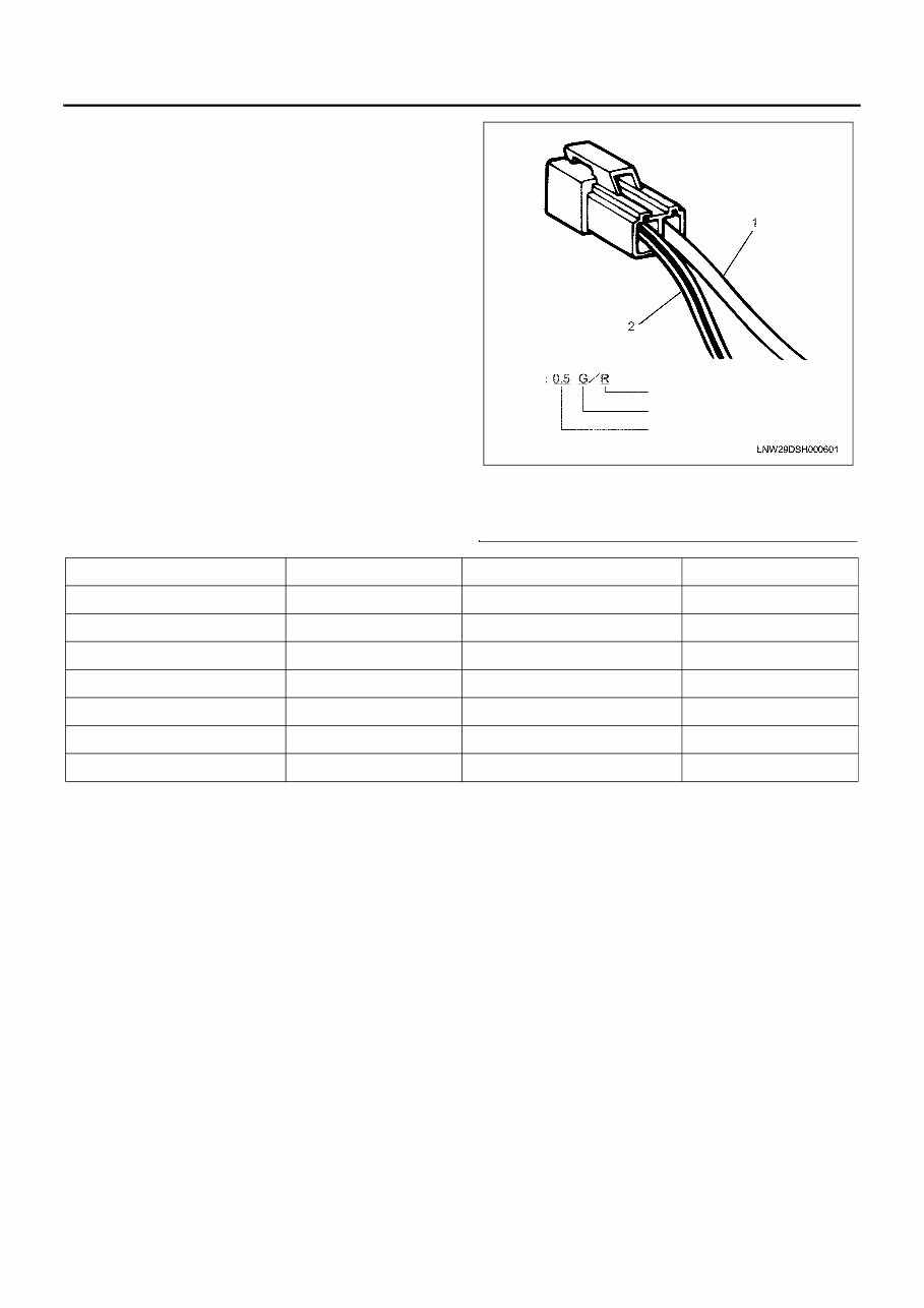
About colors of wirings
All harnesses are identified by using different colors of
claddings. The harness for the main circuit in a certain
electrical system is identified by using a single color,
while the harness for the sub circuit uses a color in
stripes. Sizes and colors coding in a wiring diagram are
as follows.
Name
1. Single color
2. Color stripe
e.g.
Red (stripe color)
Green (base color)
Harness size(0.5mm )
2
Symbol Color Symbol Color
B Black BR Brown
W White LG Light green
R Red GR Grey
G Green P Pink
Y Yellow SB Sky blue
L Blue V Violet
O Orange
Electronic control fuel injection system (Common rail type) 1E-7
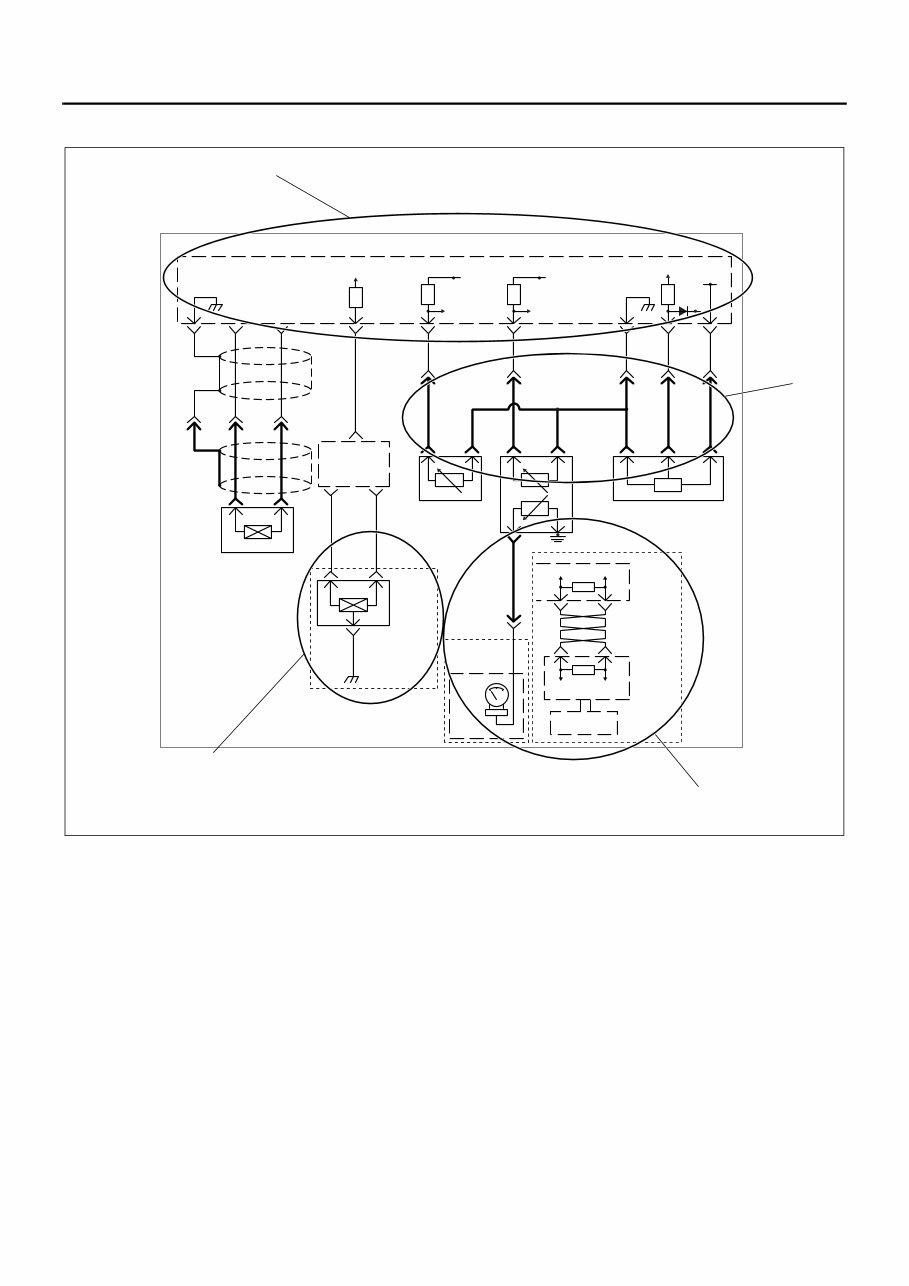
About wiring diagrams
1. Sections surrounded by long broken lines are used
to indicate the units, such as ECM.
2. Sections surrounded by dotted lines are used to
classify or differentiate the specifications of
machines. Confirmation of specifications is
needed.
3. Sections surrounded by dotted lines and marked
with a symbol (“A” in example) on the upper left are
used to classify different wiring in the specifications
of machines. Confirmation of specifications is
needed.
4. Sections surrounded by heavy lines are used to
differentiate engine harnesses from other
harnesses. Heavy lines indicate engine harnesses,
other lines indicate machine harnesses.
108
3
0.75 B
0.5
V/W
0.5
Y
2 1
E-56
2 E-98 1 E-98
19 E-57 107 E-56 106 E-56
3
2 E-93
7
2 E-90
3 E-90
0.75
R
1 E-93 1 E-90
83 E-56
0.75
Y/G
0.75
B/Y
0.75
R/B
0.75
B/Y
0.75
B/Y
0.75
L/Y
0.75
W/B
SV
84 E-56
SV
SV
Vcc
11
1
79 E-56
10
2
67 E-56
9
3
80 E-56
H-20 H-20 H-20
H-6 H-20 H-20 H-20 H-20
E-76 E-76 E-76
4 H-6
A
*
CAN HIGH CAN LOW
37 E-57 18 E-57
CAN HIGH CAN LOW
A
TSWG0078
Machine trouble
diagnosis monitor
Machine
control unit
Engine
control
module
(ECM)
Engine
coolant
temperature
gauge
Meter
Vehicle
speed sensor
Fuel temperature sensor Engine oil pressure sensor
Engine
coolant
temperature
sensor
CKP sensor
Engine control
module (ECM)
Pulse
matching
box
CKP
HIGH
signal
CKP
LOW
signal
Vehicle speed
sensor signal
Fuel temperature
sensor signal
Engine coolant
temperature
sensor signal
Engine oil pressure
sensor signal
TSWG0120
2
3
4
1
You're Reading a Preview
What's Included?
Fast Download Speeds
Online & Offline Access
Access PDF Contents & Bookmarks
Full Search Facility
Print one or all pages of your manual
$57.99
Viewed 66 Times Today


Secure transaction
What's Included?
Fast Download Speeds
Online & Offline Access
Access PDF Contents & Bookmarks
Full Search Facility
Print one or all pages of your manual
$57.99
This service manual for the Hitachi Isuzu 4H & 6H engines provides detailed troubleshooting information for the electronic control fuel injection system, specifically the common rail type used in the 4HK1 and 6HK1 industrial engines. It is a valuable resource for both professional mechanics and DIY enthusiasts, enabling them to perform service work efficiently.
The manual covers the following general contents:
- Control System
- Engine Control (Electronic control fuel injection system - Common rail type)
File Format: PDF
Total Pages: 613
Size: 14Mb
Manual Language: English
For any inquiries or if you are in search of a specific manual, feel free to reach out. Have a great day!


