

ISUZU Diesel Engine 6BG1 Instruction Manual
What's Included?
Fast Download Speeds
Offline Viewing
Access Contents & Bookmarks
Full Search Facility
Print one or all pages of your manual

GENERAL INFORMATION 1-I
SECTION 1
GENERAL INFORMATION
TABLE OF CONTENTS
ITEM PAGE
General repair instructions ............................................................................... l- 2
Notes on the format of this manual ..................................................................... l- 2
Main data and specifications ............................................................................. l- 6
Tightening torque specifications
I
........................................................................ 1- 8
Angular nut and bolt tightening method ............................................................... l-10
Major parts fixing nuts and bolts . ........................................................................ l-12
Identifications .............................................................................................. l-23
13 GENERAL INFORMATION
1 .
2 .
3 .
4 .
5 .
6 .
7 .
8 .
9 .
10 .
11 .
12 .
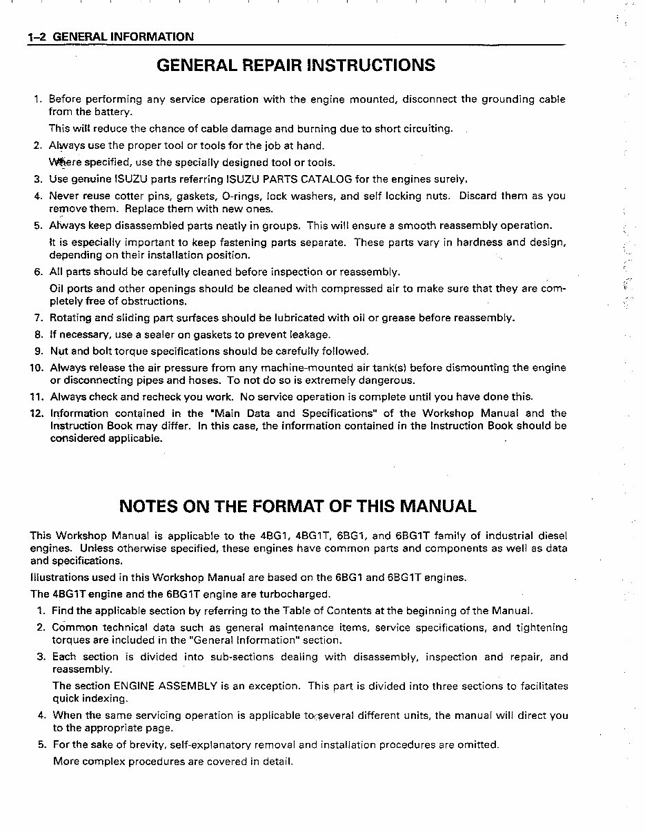
GENERAL REPAIR INSTRUCTIONS
Before performing any service operation with the engine mounted, disconnect the grounding cable
from the battery.
This will reduce the chance of cable damage and burning due to short circuiting.
Always use the proper tool or tools for the job at hand.
.
mere specified, use the specially designed tool or tools.
L
Use genuine ISUZU parts referring ISUZU PARTS CATALOG for the engines surely.
Never reuse cotter pins, gaskets, O-rings, lock washers, and self locking nuts. Discard them as you
remove them. Replace them with new ones.
Always keep disassembled parts neatly in groups. This will ensure a smooth reassembly operation.
It is especially important to keep fastening parts separate. These parts vary in hardness and design,
depending on their installation position.
‘ ,
‘ .
r. I--
All parts should be carefully cleaned before inspection or reassembly.
Oil ports and other openings should be cleaned with compressed air to make sure that they are com-
pletely free of obstructions.
Rotating and sliding part surfaces should be lubricated with oil or grease before reassembly.
If necessary, use a sealer on gaskets to prevent leakage.
Nut and bolt torque specifications should be carefully followed.
Always release the air pressure from any machine-mounted air tank(s) before dismounting the engine
or disconnecting pipes and hoses. To not do so is extremely dangerous.
Always check and recheck you work. No sewice operation is complete until you have done this.
Information contained in the “Main Data and Specifications” of the Workshop Manual and the
Instruction Book may differ. In this case, the information contained in the Instruction Bo.ok should be
considered applicable. z
NOTES ON THE FORMAT OF THIS MANUAL
This Workshop Manual is applicable to the 4BG1, 4BGlT, 6BG1, and 6BGlT family of industrial diesel
engines. Unless otherwise specified, these engines have common parts and components as well as data
and qqecifications.
Illustrations used in this Workshop Manual are based on the 6BGl and 6BGlT engines.
The 4BGlTengine and the 6BGlT engine are turbocharged.
.
1 .
2 .
3 .
4 .
5 .
Find the applicable section by referring to the Table of Contents at the beginning of the Manual.
Cdmmon technical data such as general maintenance items, service specifications, and tightening
torques are included in the “General Information” section.
Each section is divided into sub-sections dealing with disassembly, inspection and repair, and
reassembly.
The section ENGINE ASSEMBLY is an exception. This part is divided into three sections to facilitates
quick indexing.
When the same servicing operation is applicable to<--everal different units, the manual will direct you
to the appropriate page.
For the sake of brevity, self-explanatory removal and installation procedures are omitted.
More complex procedures are covered in detail.
,
GENERAL INFORMATION 1-3
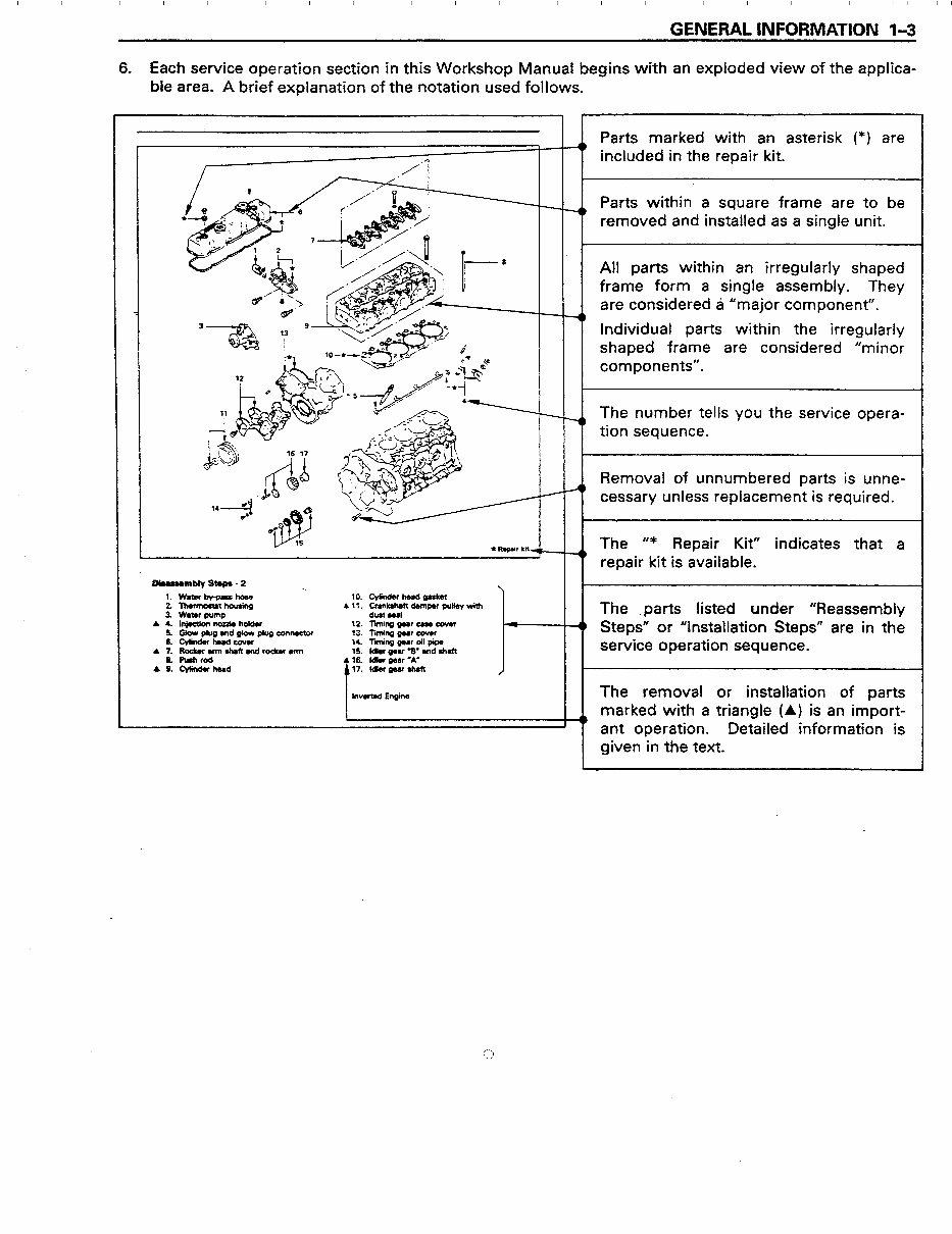
6. Each service operation section in this Workshop Manual begins with an exploded view of the applica-
ble area. A brief explanation of the notation used follows.
o&sumblystaps-2
-.
1. W8terby-passho8e
2. ThwmosUtfiou8ing
.3. WatDrpfJmp
A 4. l~rKuzleholder
5. Glow plug and gJow plug connector
6. cylllherdcowr
A 7. Rocbrarmshaftandrockerrrm
S. fbhrod
A 9. c-w
10. Cylinder he8d gultet
A 11. Crankshaftdamper pulley with
dust seal
12. liming gear cue cutter
13. liming gmr cover
14. Tf gear oil pipe
15. ldktr gear 3. rnd shaft
16. ldbr war -A’
l?. Mkr gear shaft
I
lnvwted Engine
I-
Parts marked with an asterisk (*) are
included in the repair kit.
Parts within a square frame are to be
removed and installed as a single unit.
All parts within an irregularly shaped
frame form a single assembly. They
are considered ti “major component”.
Individual parts within the irregularly
shaped frame are considered “minor
components”.
The number tells you the service opera-
tion sequence.
Removal of unnumbered parts is unne-
cessary unless replacement is required.
The ‘ I* Repair Kit” indicates that a
repair kit is available.
The .parts listed under “Reassembly
Steps” or “Installation Steps” are in the
service operation sequence.
The removal or installation of parts
marked with a triangle (A) is an import-
ant operation. Detailed information is
given in the text.

I I I I I I I I I I I I I I I I I I I I I I I I I I I I I I I I I I I I I I I I I I I I I I I I I I I I I I I I II I I I I I I&!.- 1
,
1” GENERAL INFORMATION
7. Below is a sample of the text of the Workshop Manual.
This is the item shown in the illus-
4 tration. It is marked with a triangle
(A) on the Major Components page.
Special tools are identified by the
from the upper face of the cylinder head.
Letters and numbers contained in a
circle refer to the illustration.
set.
guides.
Symbols indicate the type of service
or step to be per-
formed. A detailed explanation of
these symbols follows.
Y
Service data and specifications are
given in this table.
8. The following symbols appear throughout this Workshop Manual. They tell you the type of service
operation or step to perform.
q
CI)
. . .
0
*+ l **
III
+$+ . . .
cl
$+ l l l
ltrl
. . .
0
*
. . .
El
aB ...
.
.
l!!il
.
. . .
B!l
. . .
Removal
Installation
Disassembly
Reassembly
Alignment (Marks)
Directional Indication
Inspection
Measurement
Sealant Application
-
El
D
II)
. ..
l5l
.. .
V
?
0. . .
m
. . .
El
bl . . .
cl
0
. . .
0
qy5 l l l
cl
-b
...
Adjustment
Cleaning
Important Operation Requiring Extra Care
Specified Torque (Tighten)
Special Tool Use Required or Recommended
(lsuzu Tool or Tools)
Commercially Available Tool Use Required or
Recommended
Lubrication (Oil)
(2
Lubrication (Grease)
I I I I I I I I I I I I I I I I I I I I I I I I I I I I I I I I I I I I I I I I I I I I I I I I I I I I I I I I II I I I I I I II
I‘
GENERAL INFORMAiiON l-5
9 .
10 .
II .
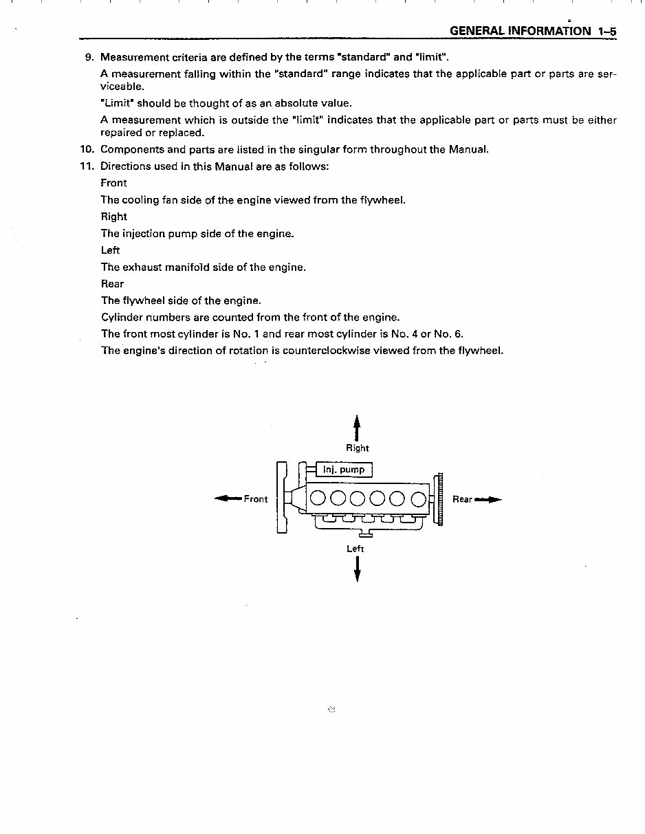
Measurement criteria are defined by the terms “standard” and “limit”.
A measurement falling within the “standard” range indicates that the applicable part or parts are ser-
vicea ble.
“Limit” should be thought of as an absolute value.
A measurement which is outside the “limit” indicates that the applicable part or parts must be either
repaired or replaced.
Components and parts are listed in the singular form throughout the Manual.
Directions used in this Manual are as follows:
Front
The cooling fan side of the engine viewed from the flywheel.
Right
The injection pump side of the engine.
Left
The exhaust manifold side of the engine.
Rear
The flywheel side of the engine.
Cylinder numbers are counted from the front of the engine.
The front most cylinder is No. 1 and rear most cylinder is No. 4 or No. 6.
The’engine’s direction of rotation is counterclockwise viewed from the flywheel.
. -
b Front
t
Right
Rear W
Left
+
I I I I I I I I I I I I I I I I I I I I I I I I I I I I I I I I I I I I I I I I I I I I I I I I I I I I I I I I II I I I I I I II
f=. - 1
l-6 GENERAL INFORMATION
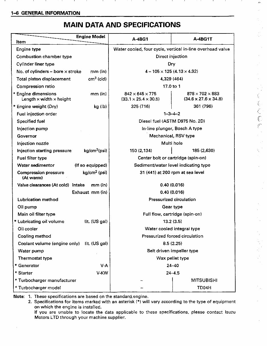
MAIN DATA AND SPECIFICATIONS
Engine Model
Item
A-4BGl A-4BGlT
-
Engine type Water cooled, four cycle, vertical in-line overhead valve
Combustion chamber type
Direct injection
Cylinder liner type Dry
No. of cylinders - bore x stroke mm (in) 4 - 105 x 125 (4.13 x 4.92)
Total piston displacement cm3 (cid) 4,329 (464)
Compression ratio
17.0 to I
f Engine dimensions mm (in) 842x645~775 878 x 702 x 883
Length x width x height (33.1 x 25.4 x 30.5) (34.6 x 27.6 x 34.8)
’ Engine weight (Dry) kg (lb)
325 (716) 361 (796)
Fuel injection order
I-3-4-2
Specified fuel
Diesel fuel (ASTM D975 No. 2D)
Injection pump
In-line plunger, Bosch A type
Governor
Mechanical, RSV type
Injection nozzle
Multi hole
injection starting pressure kg/cm2( psi) 150 (2,134)
I
185 (2,630)
Fuel filter type
Center bolt or cartridge (spin-on)
Water sedimentor (If so equipped) Sediment/water level indicating type
Compression pressure kg/cm2 (psi) 31 (441) at 200 rpm at sea level
(At warm)
Valve clearances (At cold) Intake mm (in) 0.40 (0.016)
Exhaust mm (in) 0.40 (0.016)
Lubrication method
Pressurized circulation
Oil pump
Gear type
Main oil filter type
Full flow, cartridge (spin-on)
)cLubricating oil volume lit. (US gal) 13.2 (3.5)
Oil cooler Water cooled integral type
Cooling method Pressurized forced circulation
Coolant volume (engine only) lit. (US gal) 8.5 (2.25)
Water pump
Belt driven impeller type
i
Thermostat type Wax pellet type
* Generator V-A 24-40
* Starter V-KW 24-4.5
* Turbocharger manufacturer
MITSUBISHI
* Turbocharger model
TDO4H
Note: 1. These specifications are based on the standareengine.
I
:’
!
c-
\.?,
‘L
.@-
jJ
I
*‘ I
c
.Tp’
t,. / .
r-pa.
‘ i‘
tJ
k
._
2. Specifications for items marked with an asterisk (*) will vary according to the type of equipment
on which the engine is installed.
If you are unable to locate the data applicable to these specifications, please contact lsuzu
Motors LTD through your machine supplier.
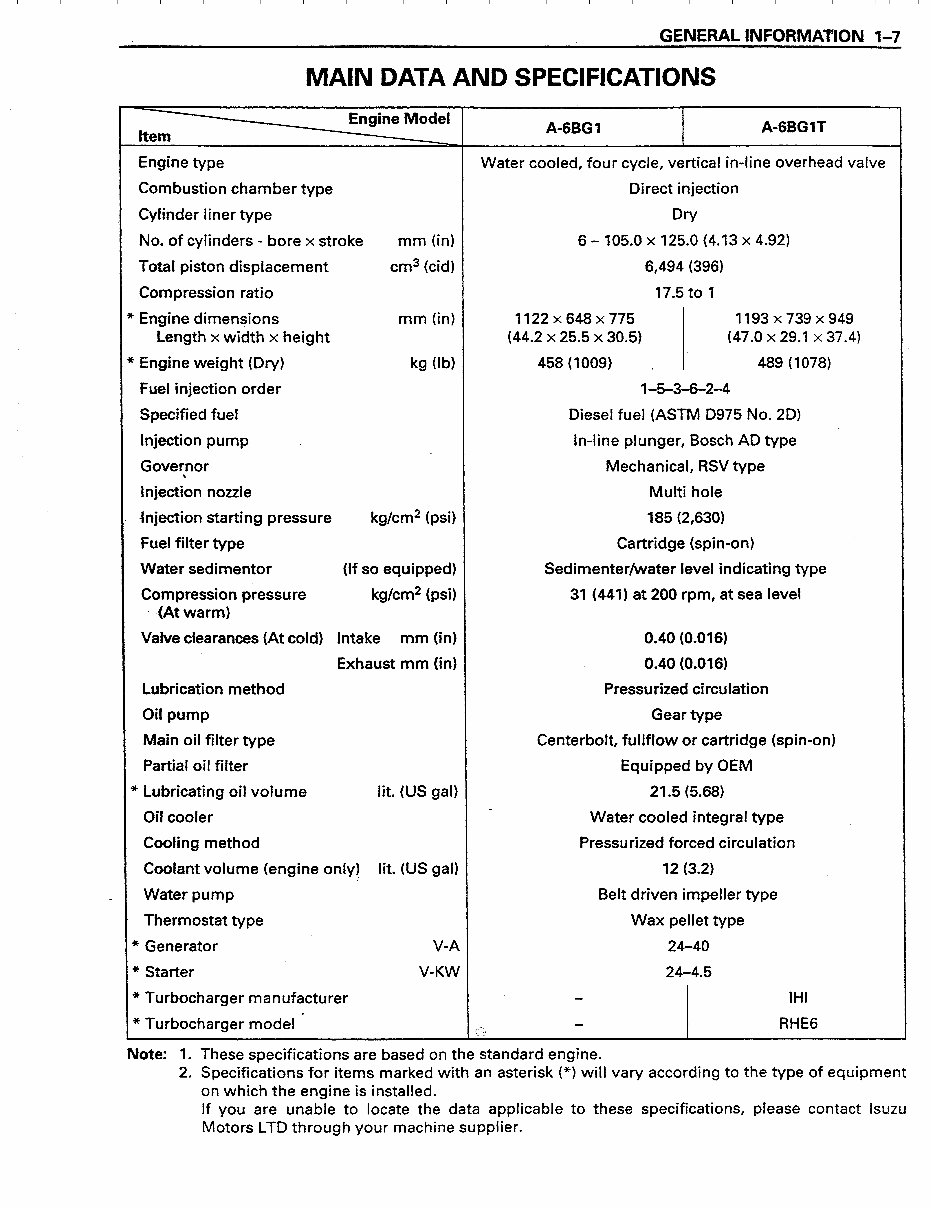
GENERAL INFORMAnON 1-7
MAIN DATA AND SPECIFICATIONS
Engine Model
Item
A-6BGl A-6BG1T
Engine type Water cooled, four cycle, vertical in-line overhead valve
Combustion chamber type Direct injection
Cylinder liner type
Dry
No. of cylinders - bore x stroke mm (in) 6 - 105.0 x 125.0 (4.13 x 4.92)
Total piston displacement cm3 (cid) 6,494 (396)
Compression ratio 17.5 to 1
Engine dimensions mm (in) 1122x648~775 1193X739X949
Length x width x height (44.2 x 25.5 x 30.5) (47.0 x 29.1 x 37.4)
Engine weight (Dv) kg (lb) 458 (1009) \ 489 (1078)
Fuel injection order l-5-3-6-2-4
Specified fuel Diesel fuel (ASTM 0975 No. 20)
injection pump . In-line plunger, Bosch AD type
Governor
Inject& nozzle
Mechanical, RSV type
Multi hole
injection starting pressure kg/cm2 (psi) 185 (2,630)
Fuel filter type Cartridge (spin-on)
Water sedimentor (if so equipped) Sedimenter/water level indicating type
Compression pressure kg/cm* (psi) 31 (441) at 200 rpm, at sea level
. .(At warm)
Valve clearances (At cold) Intake mm (in) 0.40 (0.016)
Exhaust mm (in) 0.40 (0.016)
Lubrication method Pressurized circulation
Oil pump Gear type
Main oil filter type Centerbolt, fullflow or cartridge (spin-on)
Partial oil filter Equipped by OEM
’Lubricating oil volume lit. (US gal) 21.5 (5.68)
a
Oil cooler Water cooled integral type
Cooling method Pressurized forced circulation
Coolant volume (engine only) lit. (US gal) 12 (3.2)
Water pump Belt driven impeller type
Thermostat type Wax pellet type
t Generator V-A 24-40
e Starter V-KW 24-4.5
e Turbocharger manufacturer IHI
t Turbocharger model ’
-
(yJ
RHE6
Note: 1 . These specifications are based on the standard engine.
2. Specifications for items marked with an asterisk (*) will vary according to the type of equipment
on which the engine is installed.
If you are unable to locate the data applicable to these specifications, please contact lsutu
Motors LTD through your machine supplier.
I I I I I I I I I I I I I I I I I I I I I I I I I I I I I I I I I I I I I I I I I I I I I I I I I I I I I I I I II I I I I I 1pr -4 1 I
:.
1-8 GENERAL INFORMATION
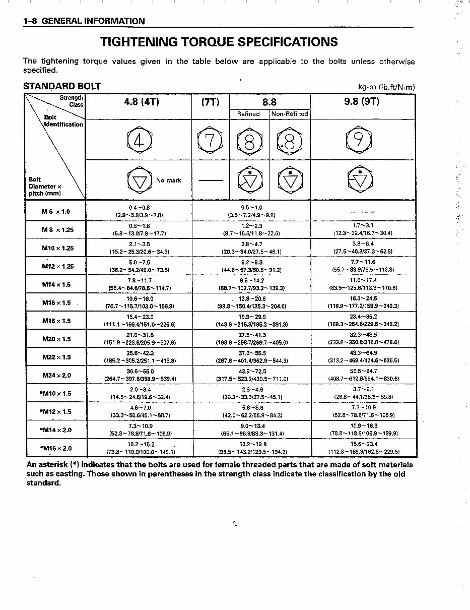
TIGHTENING TORQUE SPECIFICATIONS
The tightening torque values given in the table below are applicable to the bolts unless otherwise
specified.
STANDARD BOLT kg.m (I b.ft/N.m)
4.8 (4T) (7-n 88 0 9.8 (9T)
Refined Non-Refined
@I @@@I @
0 77 No mark -@@$I @
.
M6 x1.0 0.4-0.8 0.5-1.0
(2.9-5.813.9-7.8) (3.6-7.2/4.9-9.8)
M8 xl.25 0.8-1.8 1.2-2.3 x7-3.1
(5.8~~13.OjT.8-17.7) (8.7~16.6/11.8-22.6) (12.3-22.4/16.7-30.4)
Ml0 x 1.25 2.1-3.5 2.8-4.7 3.8-6.4
(15.2-25.3/20.6-34.3) (20.3434.0/27.5-46.1) (27.5~46.3/37.3-62.8)
M72 x 1.25 5.0-7.5 6.2-9.3 7.7-11.6
(36.2-54.2/49.0-73.6) (44.8~67.3/60.8-91.2) (55.7~83.9/75.5-113.8)
M34 x 1.5 7.8-11.7 9.5-14.2 11.6-17.4
(56.4-84.6178.5-114.7) (68.7-102.7/93.2-139.3) . (83.9~125.6/113.8-170.6)
Ml6 x 1.5 10.6-16.0 . 13.8-20.8 16.3-24.5
(76.7~115.7/103.0--156.9) (99.8-150.4/135.3-204.0) (118.9-177.2/159.9-240.3)
Nil8 x 1.5 15.4-23.0 19.9-29.9 23.4-35.2
.
(lll.l-166.4/151.0-225.6) (143.9-216.3/195.2-391.3) (169.34254.6/229.5-345.2)
nmxl.5 21.0-31.6 27.5-41.3 32.3-48.5
, (151.9-228.6/205.9-307.9) (198.9-298.7/269.7-405.0) (233.6~350.8/316.8-475.6)
M22xl.5 25.6-42.2 37.0-55.5 43.3-64.9
(185.2-305.2/251.1-413.8) (267.6-401.4/362.9-544.3) (313.2-469.4/424.6-636.5)
M24 x 2.0 36.6-55.0 43.9-72.5 56.5-84.7
(264.7-397.8/358.9-539.4) (317.5~523.9/430.5-711.0) (408.7-612.6/554.1-830.6)
*Ml0 x 1.5 2.0-3.4 2.8-4.6 3.7-6.1
(14.5-24.6/19.6-32.4) (20.3-33.3127.5-45.1) (26.8-44.1/36.3-59.8)
I
*Ml2 x 1.5 4.6-7.0 5.8-8.6 7.3-10.9
(33.3-50.6/45.1-68.7) (42.0~62.2/56.9-84.3) (52.8-78.8/7X6-106.9)
*Ml4 x 2.0 7.3-10.9 9.0-13.4 10.9-16.3
(52.8-78.8/77.6-106.9) (65.1~96.9/88.3-131.4) (78.8~118.9/106.9-159.9)
10.2-15.2 *Ml6 x 2.0
173.8~110.0/100.0-149.1;
13.2-19.8 15.6-23.4
I (95.5~143.2/129.5-194.2) (112.8-169.3/162.8-229.5)
r
J
,I
‘\
i -
&~
,a-
,<.
‘C
A
_--
r,.-
‘3
,Tc-\
: 3
\
An asterisk (*) indicates that *he bolts are used for female threaded parts that are made of soft materials
such as casting. Those shown in parentheses in the strength class indicate the classification by the old
standard.
You're Reading a Preview
What's Included?
Fast Download Speeds
Offline Viewing
Access Contents & Bookmarks
Full Search Facility
Print one or all pages of your manual
$33.99
Viewed 55 Times Today


Secure transaction
What's Included?
Fast Download Speeds
Offline Viewing
Access Contents & Bookmarks
Full Search Facility
Print one or all pages of your manual
$33.99
This Workshop Service/Repair Manual for the ISUZU DIESEL ENGINE 6BG1 is a comprehensive guide suitable for all PC-based Windows operating systems and Mac. It contains technical repair information essential for rebuilding or maintaining the ISUZU DIESEL ENGINE 6BG1, making it valuable for both professional mechanics and DIY enthusiasts.
- Lubrication & Maintenance
- Suspension
- Brakes
- Cooling System
- Electrical System
- Engine
- Fuel System
- Exhaust System
- Transmission
- Heating and Air Conditioning
- Emission Control Systems
- Body
- Wiring Diagrams
- And much more
This manual covers every part of the car and allows for easy printing of all or selected pages. It includes numerous pictures and diagrams for reference. With email delivery, there's no need to wait for shipping, providing quick access to the manual.


